2002 NISSAN TERRANO diagram
[x] Cancel search: diagramPage 1405 of 1767
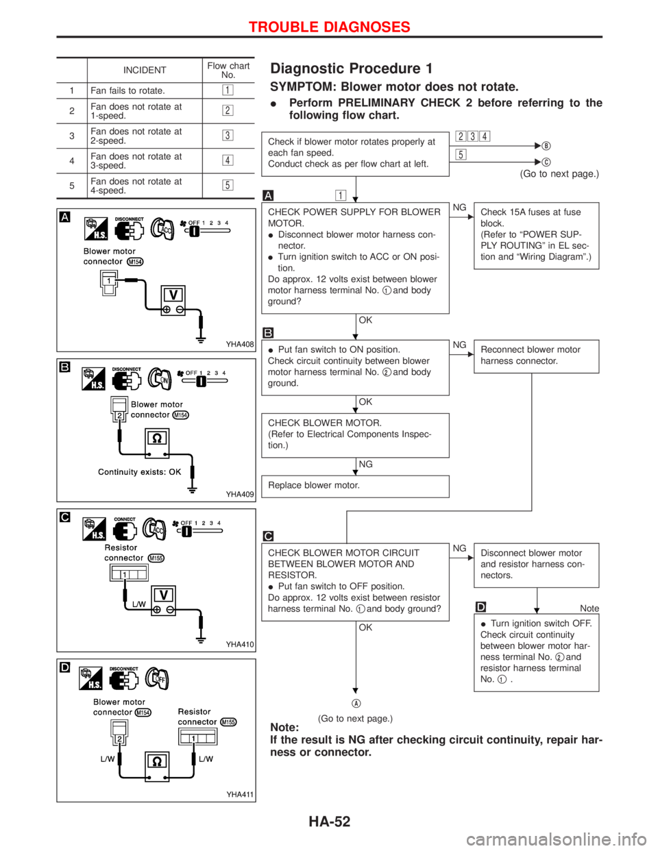
Diagnostic Procedure 1
SYMPTOM: Blower motor does not rotate.
IPerform PRELIMINARY CHECK 2 before referring to the
following flow chart.
Check if blower motor rotates properly at
each fan speed.
Conduct check as per flow chart at left.234EqB5EqC
(Go to next page.)
1
CHECK POWER SUPPLY FOR BLOWER
MOTOR.
IDisconnect blower motor harness con-
nector.
ITurn ignition switch to ACC or ON posi-
tion.
Do approx. 12 volts exist between blower
motor harness terminal No.q
1and body
ground?
OK
ENG
Check 15A fuses at fuse
block.
(Refer to ªPOWER SUP-
PLY ROUTINGº in EL sec-
tion and ªWiring Diagramº.)
IPut fan switch to ON position.
Check circuit continuity between blower
motor harness terminal No.q
2and body
ground.
OK
ENG
Reconnect blower motor
harness connector.
CHECK BLOWER MOTOR.
(Refer to Electrical Components Inspec-
tion.)
NG
Replace blower motor.
CHECK BLOWER MOTOR CIRCUIT
BETWEEN BLOWER MOTOR AND
RESISTOR.
IPut fan switch to OFF position.
Do approx. 12 volts exist between resistor
harness terminal No.q
1and body ground?
OK
ENG
Disconnect blower motor
and resistor harness con-
nectors.
Note
ITurn ignition switch OFF.
Check circuit continuity
between blower motor har-
ness terminal No.q
2and
resistor harness terminal
No.q
1.
qA
(Go to next page.)Note:
If the result is NG after checking circuit continuity, repair har-
ness or connector.
INCIDENTFlow chart
No.
1 Fan fails to rotate.
1
2Fan does not rotate at
1-speed.2
3Fan does not rotate at
2-speed.3
4Fan does not rotate at
3-speed.4
5Fan does not rotate at
4-speed.5
YHA408
YHA409
YHA410
YHA411
H
H
H
H
H
H
TROUBLE DIAGNOSES
HA-52
Page 1408 of 1767
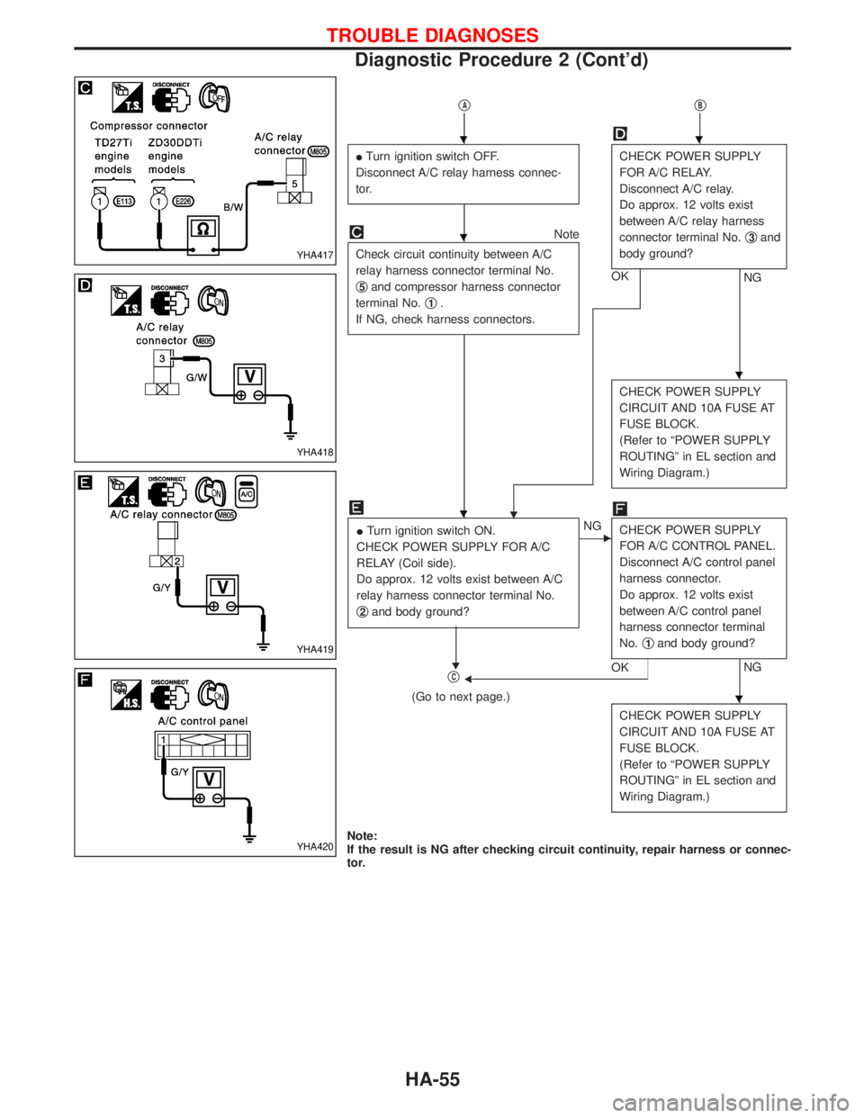
qAqB
ITurn ignition switch OFF.
Disconnect A/C relay harness connec-
tor.CHECK POWER SUPPLY
FOR A/C RELAY.
Disconnect A/C relay.
Do approx. 12 volts exist
between A/C relay harness
connector terminal No.q
3and
body ground?
NG OK
Note
Check circuit continuity between A/C
relay harness connector terminal No.
q
5and compressor harness connector
terminal No.q
1.
If NG, check harness connectors.
H
CHECK POWER SUPPLY
CIRCUIT AND 10A FUSE AT
FUSE BLOCK.
(Refer to ªPOWER SUPPLY
ROUTINGº in EL section and
Wiring Diagram.)
ITurn ignition switch ON.
CHECK POWER SUPPLY FOR A/C
RELAY (Coil side).
Do approx. 12 volts exist between A/C
relay harness connector terminal No.
q
2and body ground?
H
ENG
CHECK POWER SUPPLY
FOR A/C CONTROL PANEL.
Disconnect A/C control panel
harness connector.
Do approx. 12 volts exist
between A/C control panel
harness connector terminal
No.q
1and body ground?
NG
OKFqC
(Go to next page.)
CHECK POWER SUPPLY
CIRCUIT AND 10A FUSE AT
FUSE BLOCK.
(Refer to ªPOWER SUPPLY
ROUTINGº in EL section and
Wiring Diagram.)
Note:
If the result is NG after checking circuit continuity, repair harness or connec-
tor.
YHA417
YHA418
YHA419
YHA420
HH
H
H
H
H
TROUBLE DIAGNOSES
Diagnostic Procedure 2 (Cont'd)
HA-55
Page 1412 of 1767
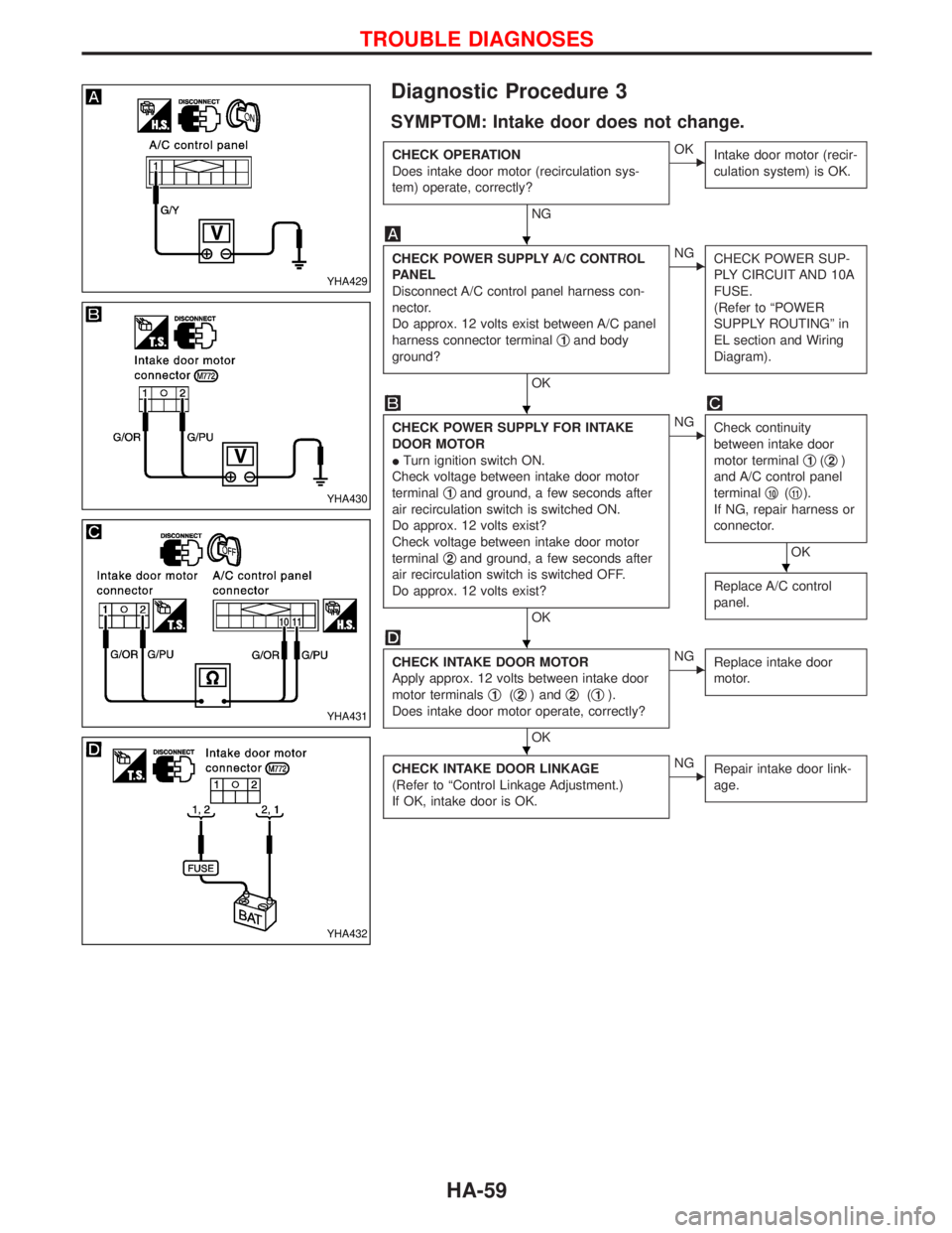
Diagnostic Procedure 3
SYMPTOM: Intake door does not change.
CHECK OPERATION
Does intake door motor (recirculation sys-
tem) operate, correctly?
NG
EOK
Intake door motor (recir-
culation system) is OK.
CHECK POWER SUPPLY A/C CONTROL
PANEL
Disconnect A/C control panel harness con-
nector.
Do approx. 12 volts exist between A/C panel
harness connector terminalq
1and body
ground?
OK
ENG
CHECK POWER SUP-
PLY CIRCUIT AND 10A
FUSE.
(Refer to ªPOWER
SUPPLY ROUTINGº in
EL section and Wiring
Diagram).
CHECK POWER SUPPLY FOR INTAKE
DOOR MOTOR
ITurn ignition switch ON.
Check voltage between intake door motor
terminalq
1and ground, a few seconds after
air recirculation switch is switched ON.
Do approx. 12 volts exist?
Check voltage between intake door motor
terminalq
2and ground, a few seconds after
air recirculation switch is switched OFF.
Do approx. 12 volts exist?
OK
ENG
Check continuity
between intake door
motor terminalq
1(q2)
and A/C control panel
terminalq
10(q11).
If NG, repair harness or
connector.
OK
Replace A/C control
panel.
CHECK INTAKE DOOR MOTOR
Apply approx. 12 volts between intake door
motor terminalsq
1(q2) andq2(q1).
Does intake door motor operate, correctly?
OK
ENG
Replace intake door
motor.
CHECK INTAKE DOOR LINKAGE
(Refer to ªControl Linkage Adjustment.)
If OK, intake door is OK.ENG
Repair intake door link-
age.
YHA429
YHA430
YHA431
YHA432
H
H
H
H
H
TROUBLE DIAGNOSES
HA-59
Page 1419 of 1767
A
ABS (anti-lock brake system).........................BR-35
ABS - Wiring diagram ....................................BR-50
A/C air flow .......................................................HA-8
A/C compressor precaution..............................HA-5
A/C control operation (manual A/C) .................HA-6
A/C relay.........................................................HA-61
A/C symptom chart (manual A/C) ..................HA-36
A/C trouble diagnoses (manual A/C) .............HA-27
A/C, M - Wiring diagram ................................HA-43
ACC/SW - Wiring diagram ...........................EC-106
Accelerator control system ...........................FE-2, 5
Accelerator position sensor .........EC-130, 368, 371
Accelerator position switch ..................EC-369, 371
Accelerator switch (F/C) ...............................EC-104
Accelerator wire adjustment .............................FE-5
Accelerator work unit....................................EC-365
A/CCUT - Wiring diagram ............................EC-289
Air bag ..............................................................RS-6
Air bag disposal..............................................RS-20
Air bag precautions ...........................................GI-3
Air bleeding (hydraulic clutch) ..........................CL-6
Air bleeding for brake system ..........................BR-8
Air cleaner filter replacement ..............MA-5, 20, 24
Air conditioner cut control ..............EC-22, 311, 440
Air control cable adjustment...........................HA-62
Air flow meter - See Mass air flow
sensor .................................................EC-88, 356
Alternator ........................................................SC-27
Angular tightening application..........................EM-3
Antenna .................................................EL-111, 127
Anti-lock brake system - See ABS .................BR-37
Anti-lock brake system - Wiring
diagram .......................................................BR-50
APS - Wiring diagram ..................................EC-133
ASCD vacuum hose ......................................MA-40
A/T - Wiring diagram .........................................AT-7
A/T - Wiring diagram - AT - PNP/SW .............AT-87
A/T - Wiring diagram - AT - VSS A/T ..............AT-49
A/T control ....................................................EC-155
A/T diagnosis communication line ...............EC-155
A/T fluid checking ............................................AT-27
A/T fluid temperature sensor...........................AT-76
A/T mode switch..............................................AT-94
A/T self-diagnoses ....................................AT-14, 19
A/T Wiring diagram - AT - ENG SS ................AT-79
A/T Wiring diagram AT - BA/FTS ....................AT-75
A/T Wiring diagram AT - LPSV .......................AT-82
A/T Wiring diagram AT - OVRCSV .................AT-68
A/T Wiring diagram AT - SSV/A ......................AT-62
A/T Wiring diagram AT - SSV/B ......................AT-65
A/T Wiring diagram AT - TCV .........................AT-71
A/T Wiring diagram AT - TPS..........................AT-56
A/T Wiring diagram AT - VSSMTR .................AT-52
AT/C - Wiring diagram..................................EC-157
Audio......................................................EL-111, 113
AUDIO - Wiring diagram ...............................EL-115Audio and A/C control removal and
installation - See Instrument panel .............BT-16
Auto lock free running hub .............................FA-14
Automatic transmission number ......................GI-30
Axle housing (rear) ...........................................RA-8
B
Back Door .......................................................BT-14
Back door opener - See Back door ................BT-14
Back door trim.................................................BT-18
Back door window...........................................BT-43
Back-up lamp ..................................................EL-49
Back-up lamp switch (M/T) ........................MT-6, 10
BACK/L - Wiring diagram................................EL-49
Ball joint front axle ..........................................FA-36
Basic inspection .....................................EC-50, 338
Battery ..............................................................SC-3
Battery Voltage .............................................EC-153
Blower motor ..................................................HA-60
Blower resistor................................................HA-60
Body alignment ...............................................BT-49
BOOST - Wiring diagram .............................EC-217
Boring/horning cylinder block.........................EM-74
Brake booster .................................................BR-17
Brake fluid change ...........................................BR-5
Brake fluid level ...........................MA-17, 36, 40, 43
Brake fluid level and line check .......................BR-5
Brake hydraulic line......................................BR-5, 6
Brake inspection ..........................MA-36, 40, 41, 42
Brake lines and cables inspection.....MA-36, 40, 42
Brake lining wear temporary checking ....MA-36, 42
Brake master cylinder ....................................BR-16
Brake pedal ....................................................BR-14
Brake switch .................................................EC-400
BRK/SW - Wiring diagram ...........................EC-205
Bumper, front ....................................................BT-6
Bumper, rear .....................................................BT-8
C
Camshaft ........................................................EM-30
Camshaft position sensor (PUMP)...............EC-161
Center case (Transfer) ......................................TF-9
CHARGE - Wiring diagram ............................SC-24
Charge air pressure sensor .........................EC-215
Charging system ............................................SC-23
Chassis and body maintenance ....................MA-36
CIGAR - Wiring diagram ...............................EL-105
Cigarette lighter.............................................EL-104
Circuit breaker.................................................EL-17
CKPS - Wiring diagram ................................EC-147
Clock .............................................................EL-104
CLOCK - Wiring diagram ..............................EL-106
Clutch cover ..............................................CL-11, 12
Clutch disc ......................................................CL-11
Clutch fluid level ......................................MA-17, 36
Clutch master cylinder ..................................CL-7, 8
ALPHABETICAL INDEX
IDX-2
Page 1420 of 1767
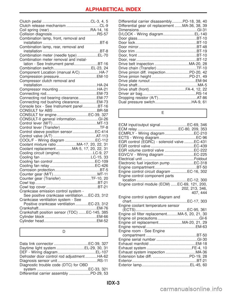
Clutch pedal .............................................CL-3, 4, 5
Clutch release mechanism ...............................CL-9
Coil spring (rear) ......................................RA-14, 16
Collision diagnosis..........................................RS-57
Combination lamp, front, removal and
installation .....................................................BT-6
Combination lamp, rear, removal and
installation .....................................................BT-8
Combination meter (needle type) ...................EL-70
Combination meter removal and instal-
lation - See Instrument panel......................BT-16
Combination switch...................................EL-23, 24
Component Location (manual A/C) ..................HA-7
Compression pressure ...................................EM-10
Compressor clutch removal and
installation ...................................................HA-24
Compressor mounting ....................................HA-21
Connecting rod...............................................EM-73
Connecting rod bearing clearance.................EM-77
Connecting rod bushing clearance ................EM-73
Console box - See Instrument panel ..............BT-16
CONSULT for ABS .........................................BR-58
CONSULT for engine .............................EC-39, 327
CONSULT-II general information.....................GI-26
Control lever (M/T) .........................................MT-13
Control lever (Transfer) .....................................TF-8
Control sleeve position sensor .....................EC-414
Control valve (A/T) ........................................AT-113
COOL/F - Wiring diagram ............................EC-112
Coolant mixture ratio ...................MA-17, 20, 22, 31
Coolant replacement ...............MA-5, 17, 20, 22, 31
Cooling circuit (engine)...............................LC-9, 27
Cooling fan ...............................................LC-15, 33
Cooling fan control .......................................EC-109
Cooling fan relay ..........................................EC-426
Corrosion protection..........................................BT-5
Counter gear (M/T) .........................................MT-11
Counter gear (Transfer) ............................TF-10, 20
Cowl top ..........................................................BT-21
Cowl top cover ................................................BT-21
Crankcase emission control system -
See positive crankcase ventilation .....EC-23, 312
Crankcase ventilation system - See
Positive crankcase ventilation ............EC-23, 312
Crankshaft ......................................................EM-76
Crankshaft position sensor (TDC) .......EC-145, 385
Cylinder block ................................................EM-66
Cylinder head .................................................EM-52
D
Data link connector ................................EC-39, 327
Daytime light system ..........................EL-29, 30, 31
DEF - Wiring diagram ...................................EL-107
Defroster door control rod adjustment ...........HA-62
Diagnosis sensor unit .....................................RS-11
Diagnostic trouble code (DTC) for OBD
system ................................................EC-33, 321
Differential carrier assembly ....................PD-29, 53Differential carrier disassembly..........PD-18, 38, 40
Differential gear oil replacement .......MA-36, 38, 39
Dimensions ......................................................GI-31
D/LOCK - Wiring diagram .............................EL-140
Door glass .......................................................BT-10
Door lock .........................................................BT-10
Door mirror ......................................................BT-48
Door trim .........................................................BT-19
Door, front .......................................................BT-10
Door, rear ........................................................BT-12
Drive belt inspection ................................MA-20, 28
Drive chain (Transfer) .....................................TF-10
Drive pinion diff. inspection ......................PD-20, 42
Drive pinion height ...................................PD-21, 49
Drive plate runout ..........................................EM-94
Drive shaft ........................................................MA-5
Drive shaft (front)..................................FA-4, 12, 22
Driver air bag..................................................RS-14
Dropping resistor (A/T)....................................AT-86
Dual pressure switch..................................HA-9, 61
E
ECM input/output signal .........................EC-69, 346
ECM relay ......................................EC-80, 209, 353
ECMRLY - Wiring diagram ...........................EC-210
ECTS - Wiring diagram ..................................EC-96
EGR control (EGRC) - solenoid valve .........EC-431
EGR control valve ........................................EC-439
EGR volume control valve ...........................EC-222
EGVC/V - Wiring diagram ............................EC-225
Electrical unit ................................................Foldout
Electronic fuel injection pump ......................EC-318
Engine compartment .......................................BT-50
Engine control circuit diagram ...............EC-16, 302
Engine control component parts
location ...............................................EC-12, 300
Engine control module (ECM) ......EC-69, 121, 200,
202, 213, 346,
407, 444
Engine control system diagram and
chart....................................................EC-17, 303
Engine coolant temperature sensor
(ECTS)................................................EC-95, 361
Engine oil filter replacement..........MA-5, 20, 21, 30
Engine oil precautions .......................................GI-6
Engine oil replacement ......................MA-20, 21, 29
Engine removal ..............................................EM-63
Engine room - See Engine
compartment ...............................................BT-50
Engine serial number ......................................GI-30
Exhaust manifold ...........................................EM-18
Exhaust system ..........................................FE-4, 10
Exhaust system inspection ............................MA-36
Extension tube diff. ..................................PD-19, 28
Exterior ............................................................BT-21
Exterior lamp.............................................EL-45, 60
ALPHABETICAL INDEX
IDX-3
Page 1421 of 1767
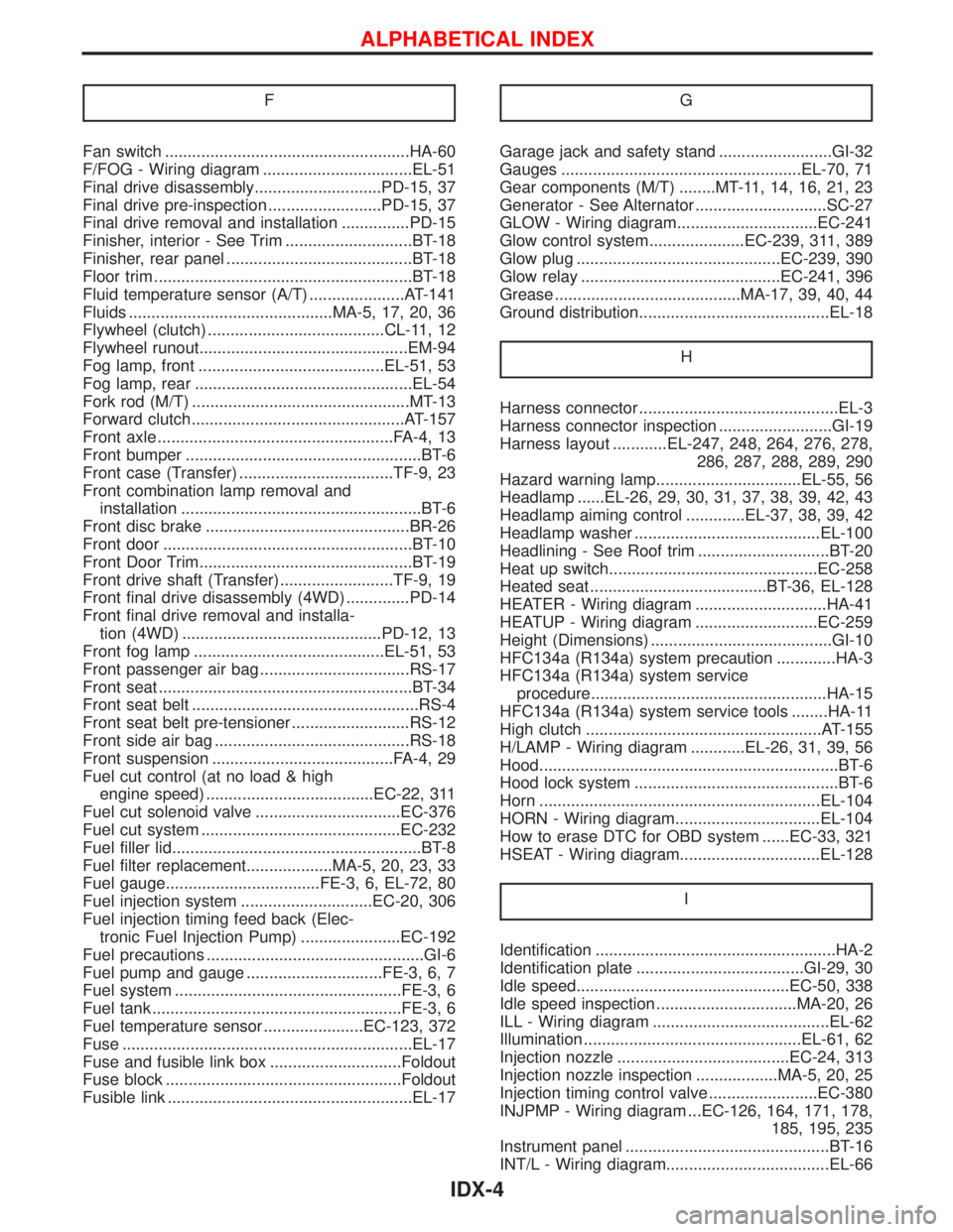
F
Fan switch ......................................................HA-60
F/FOG - Wiring diagram .................................EL-51
Final drive disassembly............................PD-15, 37
Final drive pre-inspection .........................PD-15, 37
Final drive removal and installation ...............PD-15
Finisher, interior - See Trim ............................BT-18
Finisher, rear panel .........................................BT-18
Floor trim .........................................................BT-18
Fluid temperature sensor (A/T) .....................AT-141
Fluids .............................................MA-5, 17, 20, 36
Flywheel (clutch) .......................................CL-11, 12
Flywheel runout..............................................EM-94
Fog lamp, front .........................................EL-51, 53
Fog lamp, rear ................................................EL-54
Fork rod (M/T) ................................................MT-13
Forward clutch...............................................AT-157
Front axle ....................................................FA-4, 13
Front bumper ....................................................BT-6
Front case (Transfer) ..................................TF-9, 23
Front combination lamp removal and
installation .....................................................BT-6
Front disc brake .............................................BR-26
Front door .......................................................BT-10
Front Door Trim...............................................BT-19
Front drive shaft (Transfer) .........................TF-9, 19
Front final drive disassembly (4WD) ..............PD-14
Front final drive removal and installa-
tion (4WD) ............................................PD-12, 13
Front fog lamp ..........................................EL-51, 53
Front passenger air bag .................................RS-17
Front seat ........................................................BT-34
Front seat belt ..................................................RS-4
Front seat belt pre-tensioner ..........................RS-12
Front side air bag ...........................................RS-18
Front suspension ........................................FA-4, 29
Fuel cut control (at no load & high
engine speed) .....................................EC-22, 311
Fuel cut solenoid valve ................................EC-376
Fuel cut system ............................................EC-232
Fuel filler lid.......................................................BT-8
Fuel filter replacement...................MA-5, 20, 23, 33
Fuel gauge..................................FE-3, 6, EL-72, 80
Fuel injection system .............................EC-20, 306
Fuel injection timing feed back (Elec-
tronic Fuel Injection Pump) ......................EC-192
Fuel precautions ................................................GI-6
Fuel pump and gauge ..............................FE-3, 6, 7
Fuel system ..................................................FE-3, 6
Fuel tank .......................................................FE-3, 6
Fuel temperature sensor ......................EC-123, 372
Fuse ................................................................EL-17
Fuse and fusible link box .............................Foldout
Fuse block ....................................................Foldout
Fusible link ......................................................EL-17GGarage jack and safety stand .........................GI-32
Gauges .....................................................EL-70, 71
Gear components (M/T) ........MT-11, 14, 16, 21, 23
Generator - See Alternator .............................SC-27
GLOW - Wiring diagram...............................EC-241
Glow control system.....................EC-239, 311, 389
Glow plug .............................................EC-239, 390
Glow relay ............................................EC-241, 396
Grease .........................................MA-17, 39, 40, 44
Ground distribution..........................................EL-18
H
Harness connector ............................................EL-3
Harness connector inspection .........................GI-19
Harness layout ............EL-247, 248, 264, 276, 278,
286, 287, 288, 289, 290
Hazard warning lamp................................EL-55, 56
Headlamp ......EL-26, 29, 30, 31, 37, 38, 39, 42, 43
Headlamp aiming control .............EL-37, 38, 39, 42
Headlamp washer .........................................EL-100
Headlining - See Roof trim .............................BT-20
Heat up switch..............................................EC-258
Heated seat .......................................BT-36, EL-128
HEATER - Wiring diagram .............................HA-41
HEATUP - Wiring diagram ...........................EC-259
Height (Dimensions) ........................................GI-10
HFC134a (R134a) system precaution .............HA-3
HFC134a (R134a) system service
procedure....................................................HA-15
HFC134a (R134a) system service tools ........HA-11
High clutch ....................................................AT-155
H/LAMP - Wiring diagram ............EL-26, 31, 39, 56
Hood..................................................................BT-6
Hood lock system .............................................BT-6
Horn ..............................................................EL-104
HORN - Wiring diagram................................EL-104
How to erase DTC for OBD system ......EC-33, 321
HSEAT - Wiring diagram...............................EL-128
I
Identification .....................................................HA-2
Identification plate .....................................GI-29, 30
Idle speed...............................................EC-50, 338
Idle speed inspection ...............................MA-20, 26
ILL - Wiring diagram .......................................EL-62
Illumination ................................................EL-61, 62
Injection nozzle ......................................EC-24, 313
Injection nozzle inspection ..................MA-5, 20, 25
Injection timing control valve ........................EC-380
INJPMP - Wiring diagram ...EC-126, 164, 171, 178,
185, 195, 235
Instrument panel .............................................BT-16
INT/L - Wiring diagram....................................EL-66
ALPHABETICAL INDEX
IDX-4
Page 1422 of 1767
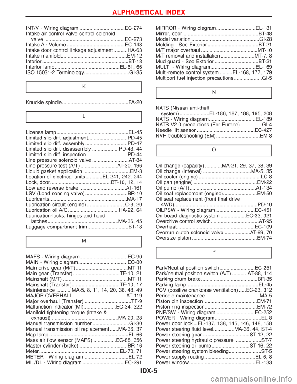
INT/V - Wiring diagram ................................EC-274
Intake air control valve control solenoid
valve .........................................................EC-273
Intake Air Volume .........................................EC-143
Intake door control linkage adjustment ..........HA-63
Intake manifold...............................................EM-12
Interior .............................................................BT-18
Interior lamp ..............................................EL-61, 66
ISO 15031-2 Terminology................................GI-35
K
Knuckle spindle ...............................................FA-20
L
License lamp ...................................................EL-45
Limited slip diff. adjustment............................PD-45
Limited slip diff. assembly ..............................PD-47
Limited slip diff. disassembly ...................PD-43, 44
Limited slip diff. inspection .............................PD-44
Line pressure solenoid valve ..........................AT-84
Line pressure test (A/T) ..........................AT-30, 196
Liquid gasket application .................................EM-3
Location of electrical units ............EL-241, 242, 244
Lock, door ...........................................BT-10, 12, 14
Low and reverse brake .................................AT-161
LSV (Load sensing valve) ..............................BR-10
Lubricants.......................................................MA-17
Lubrication circuit (engine) .........................LC-3, 20
Lubrication oil A/C ....................................HA-22, 64
Lubrication-locks, hinges and hood
latches ..................................................MA-36, 45
Luggage compartment trim .............................BT-18
M
MAFS - Wiring diagram..................................EC-90
MAIN - Wiring diagram...................................EC-80
Main drive gear (M/T) .....................................MT-11
Main gear (Transfer) .................................TF-10, 21
Mainshaft (M/T) ..............................................MT-11
Mainshaft (Transfer)..................................TF-10, 17
Maintenance ...........MA-5, 8, 11, 14, 20, 36, 48, 49
MAJOR OVERHALL ......................................AT-119
Major overhaul (Transfer) .................................TF-9
Malfunction indicator (MI).......................EC-34, 322
Manifold tightening torque (intake &
exhaust) ...............................................MA-20, 28
Manual transmission number ..........................GI-30
Manual transmission oil replacement ......MA-36, 37
Map lamp ........................................................EL-66
Mass air flow sensor (MAFS) ................EC-88, 356
Master cylinder (brake) ..................................BR-16
Meter .........................................................EL-70, 71
METER - Wiring diagram................................EL-72
MIL/DL - Wiring diagram ..............................EC-291MIRROR - Wiring diagram............................EL-131
Mirror, door......................................................BT-48
Model variation ................................................GI-28
Molding - See Exterior ....................................BT-21
M/T major overhaul ........................................MT-10
M/T removal and installation ........................MT-7, 8
Mud guard - See Exterior ...............................BT-21
MULTI - Wiring diagram................................EL-169
Multi-remote control system .........EL-168, 177, 179
Multiport fuel injection precautions ....................GI-5
N
NATS (Nissan anti-theft
system) .....................EL-186, 187, 188, 195, 208
NATS - Wiring diagram .................................EL-189
NATS V2.0 precautions (For Europe) ...............GI-4
Needle lift sensor .........................................EC-427
NVH troubleshooting (EM) ...............................EM-8
O
Oil change (capacity) ............MA-21, 29, 37, 38, 39
Oil change (interval) ..................................MA-5, 35
Oil cooler (engine) ............................................LC-8
Oil pan (engine) .............................................EM-22
Oil pump (A/T)...............................................AT-134
Oil seal replacement (engine)........................EM-50
Oil seal replacement (front final drive
4WD)...........................................................PD-10
OILPSW - Wiring diagram............................EC-451
On board diagnostic system ..................EC-33, 321
Overdrive control switch..................................AT-95
Overheat .......................................................EC-109
Overrun clutch solenoid valve ..................AT-69, 70
Oversize piston ..............................................EM-74
P
Park/Neutral position switch .........................EC-251
Park/neutral position switch (A/T) ...........AT-88, 114
Parking drum brake ........................................BR-35
Parking lamp ...................................................EL-45
PCV (positive crankcase ventilation) .....EC-23, 312
Periodic maintenance ......................................MA-5
Piston pin inspection ......................................EM-71
Piston ring inspection.....................................EM-72
PNP/SW - Wiring diagram ...........................EC-252
POWER - Wiring diagram.................................EL-8
Power door lock ...EL-137, 138, 145, 146, 148, 158
Power steering fluid level...............MA-36, 44, ST-4
Power steering gear .................................ST-12, 22
Power steering hydraulic pressure ...................ST-7
Power steering oil pump ...........................ST-16, 22
Power steering system bleeding.......................ST-5
Power supply routing ....................................EL-6, 8
Power window ...............................................EL-133
ALPHABETICAL INDEX
IDX-5
Page 1423 of 1767
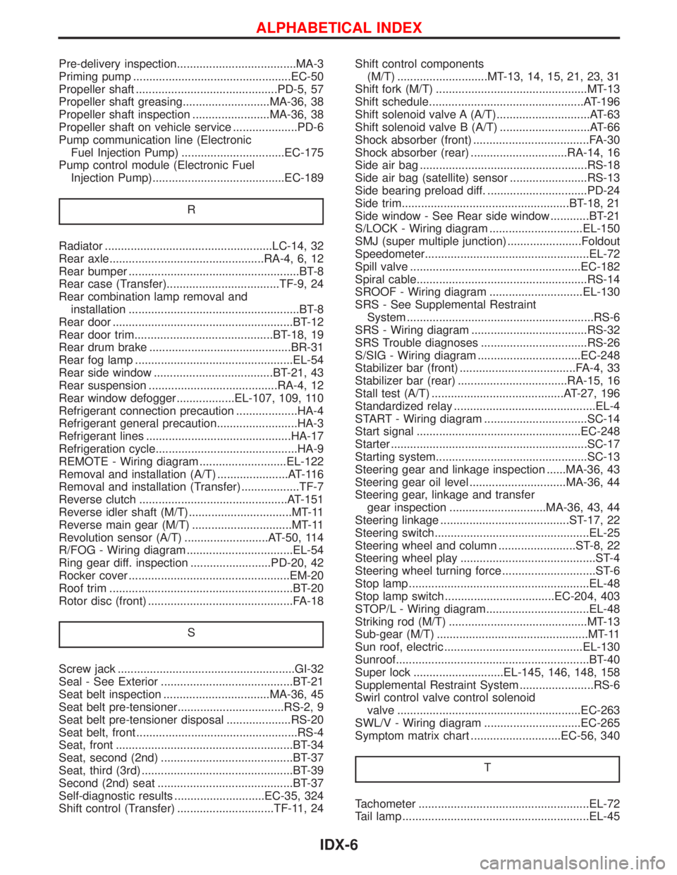
Pre-delivery inspection.....................................MA-3
Priming pump .................................................EC-50
Propeller shaft ............................................PD-5, 57
Propeller shaft greasing...........................MA-36, 38
Propeller shaft inspection ........................MA-36, 38
Propeller shaft on vehicle service ....................PD-6
Pump communication line (Electronic
Fuel Injection Pump) ................................EC-175
Pump control module (Electronic Fuel
Injection Pump).........................................EC-189
R
Radiator ....................................................LC-14, 32
Rear axle................................................RA-4, 6, 12
Rear bumper .....................................................BT-8
Rear case (Transfer)...................................TF-9, 24
Rear combination lamp removal and
installation .....................................................BT-8
Rear door ........................................................BT-12
Rear door trim...........................................BT-18, 19
Rear drum brake ............................................BR-31
Rear fog lamp .................................................EL-54
Rear side window .....................................BT-21, 43
Rear suspension ........................................RA-4, 12
Rear window defogger..................EL-107, 109, 110
Refrigerant connection precaution ...................HA-4
Refrigerant general precaution.........................HA-3
Refrigerant lines .............................................HA-17
Refrigeration cycle............................................HA-9
REMOTE - Wiring diagram ...........................EL-122
Removal and installation (A/T) ......................AT-116
Removal and installation (Transfer) ..................TF-7
Reverse clutch ..............................................AT-151
Reverse idler shaft (M/T)................................MT-11
Reverse main gear (M/T) ...............................MT-11
Revolution sensor (A/T) ..........................AT-50, 114
R/FOG - Wiring diagram .................................EL-54
Ring gear diff. inspection .........................PD-20, 42
Rocker cover ..................................................EM-20
Roof trim .........................................................BT-20
Rotor disc (front) .............................................FA-18
S
Screw jack .......................................................GI-32
Seal - See Exterior .........................................BT-21
Seat belt inspection .................................MA-36, 45
Seat belt pre-tensioner.................................RS-2, 9
Seat belt pre-tensioner disposal ....................RS-20
Seat belt, front ..................................................RS-4
Seat, front .......................................................BT-34
Seat, second (2nd) .........................................BT-37
Seat, third (3rd) ...............................................BT-39
Second (2nd) seat ..........................................BT-37
Self-diagnostic results ............................EC-35, 324
Shift control (Transfer) ..............................TF-11, 24Shift control components
(M/T) ............................MT-13, 14, 15, 21, 23, 31
Shift fork (M/T) ...............................................MT-13
Shift schedule................................................AT-196
Shift solenoid valve A (A/T).............................AT-63
Shift solenoid valve B (A/T) ............................AT-66
Shock absorber (front) ....................................FA-30
Shock absorber (rear) ..............................RA-14, 16
Side air bag ....................................................RS-18
Side air bag (satellite) sensor ........................RS-13
Side bearing preload diff. ...............................PD-24
Side trim....................................................BT-18, 21
Side window - See Rear side window ............BT-21
S/LOCK - Wiring diagram .............................EL-150
SMJ (super multiple junction) .......................Foldout
Speedometer...................................................EL-72
Spill valve .....................................................EC-182
Spiral cable.....................................................RS-14
SROOF - Wiring diagram .............................EL-130
SRS - See Supplemental Restraint
System ..........................................................RS-6
SRS - Wiring diagram ....................................RS-32
SRS Trouble diagnoses .................................RS-26
S/SIG - Wiring diagram ................................EC-248
Stabilizer bar (front) ....................................FA-4, 33
Stabilizer bar (rear) ..................................RA-15, 16
Stall test (A/T) .........................................AT-27, 196
Standardized relay ............................................EL-4
START - Wiring diagram ................................SC-14
Start signal ...................................................EC-248
Starter .............................................................SC-17
Starting system...............................................SC-13
Steering gear and linkage inspection ......MA-36, 43
Steering gear oil level ..............................MA-36, 44
Steering gear, linkage and transfer
gear inspection ..............................MA-36, 43, 44
Steering linkage ........................................ST-17, 22
Steering switch................................................EL-25
Steering wheel and column ........................ST-8, 22
Steering wheel play ..........................................ST-4
Steering wheel turning force .............................ST-6
Stop lamp ........................................................EL-48
Stop lamp switch ..................................EC-204, 403
STOP/L - Wiring diagram................................EL-48
Striking rod (M/T) ...........................................MT-13
Sub-gear (M/T) ...............................................MT-11
Sun roof, electric ...........................................EL-130
Sunroof............................................................BT-40
Super lock ............................EL-145, 146, 148, 158
Supplemental Restraint System .......................RS-6
Swirl control valve control solenoid
valve .........................................................EC-263
SWL/V - Wiring diagram ..............................EC-265
Symptom matrix chart ............................EC-56, 340
T
Tachometer .....................................................EL-72
Tail lamp ..........................................................EL-45
ALPHABETICAL INDEX
IDX-6