2002 LAND ROVER DISCOVERY lock
[x] Cancel search: lockPage 1289 of 1672
PANEL REPAIRS
77-2-40 REPAIRS
13.Fit front door striker to B/C post, fit Torx bolts
and tighten to 26 Nm (19 lbf.ft).
14.Fit rear door.
+ DOORS, REPAIRS, Door - rear.
15.Connect leads/multiplug to alternator.
16.Connect battery leads, negative lead last.
Panel body side assembly
Remove
1.Disconnect both battery leads, negative lead
first.
2.Disconnect leads/multiplug from alternator.
3.Remove loadspace side trim casing.
+ INTERIOR TRIM COMPONENTS,
REPAIRS, Trim casing - side - loadspace.
4.Remove head lining rear trim finisher.
5.Remove rear head rests, if fitted.
6.Remove body side rear glass.
+ SCREENS, REPAIRS, Glass - body
side - rear.
7.Remove rear bumper assembly.
+ EXTERIOR FITTINGS, REPAIRS,
Bumper assembly - rear - up to 03MY.
8.Remove rear bumper finisher.
9.Remove rear wheel arch liner.
+ EXTERIOR FITTINGS, REPAIRS,
Liner - wheel arch - rear.
10.Remove mud flap.
11.Remove tread plate from rear door aperture.
12.Remove rear door aperture seal.
13.Remove rear door striker from 'D' post.
14.Remove 'D' post outer trim finisher.
15.Remove wheel arch trim finisher.
16.Remove side drip rail finisher.
17. RH side: Remove tail door.
18. LH side: Remove tail door striker and setting
block from 'E' post.
19.Remove tail door tread plate.
20.Remove loadspace carpet retainer.
21.Remove tail door aperture seal.
22.Remove tail lamp.
+ LIGHTING, REPAIRS, Lamp - tail.
23. RH side: Remove fuel filler flap.
24. RH side: Remove fuel filler tube.
+ FUEL DELIVERY SYSTEM - V8,
REPAIRS, Filler tube - fuel.
25.Remove aerial amplifier.
26.Remove relevant wiring from body side area.
Page 1290 of 1672
PANEL REPAIRS
REPAIRS 77-2-41
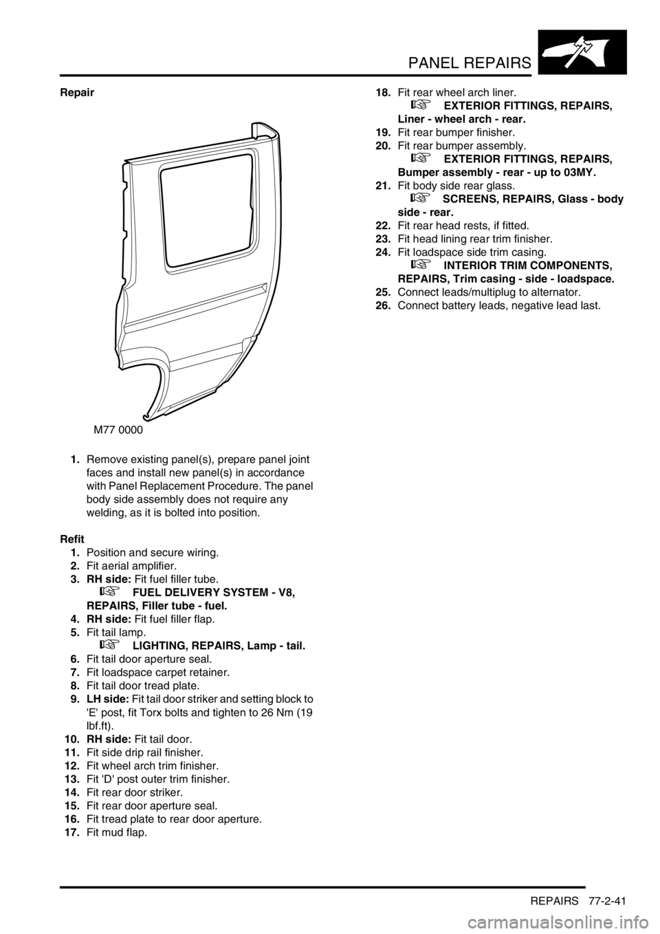
Repair
1.Remove existing panel(s), prepare panel joint
faces and install new panel(s) in accordance
with Panel Replacement Procedure. The panel
body side assembly does not require any
welding, as it is bolted into position.
Refit
1.Position and secure wiring.
2.Fit aerial amplifier.
3. RH side: Fit fuel filler tube.
+ FUEL DELIVERY SYSTEM - V8,
REPAIRS, Filler tube - fuel.
4. RH side: Fit fuel filler flap.
5.Fit tail lamp.
+ LIGHTING, REPAIRS, Lamp - tail.
6.Fit tail door aperture seal.
7.Fit loadspace carpet retainer.
8.Fit tail door tread plate.
9. LH side: Fit tail door striker and setting block to
'E' post, fit Torx bolts and tighten to 26 Nm (19
lbf.ft).
10. RH side: Fit tail door.
11.Fit side drip rail finisher.
12.Fit wheel arch trim finisher.
13.Fit 'D' post outer trim finisher.
14.Fit rear door striker.
15.Fit rear door aperture seal.
16.Fit tread plate to rear door aperture.
17.Fit mud flap.18.Fit rear wheel arch liner.
+ EXTERIOR FITTINGS, REPAIRS,
Liner - wheel arch - rear.
19.Fit rear bumper finisher.
20.Fit rear bumper assembly.
+ EXTERIOR FITTINGS, REPAIRS,
Bumper assembly - rear - up to 03MY.
21.Fit body side rear glass.
+ SCREENS, REPAIRS, Glass - body
side - rear.
22.Fit rear head rests, if fitted.
23.Fit head lining rear trim finisher.
24.Fit loadspace side trim casing.
+ INTERIOR TRIM COMPONENTS,
REPAIRS, Trim casing - side - loadspace.
25.Connect leads/multiplug to alternator.
26.Connect battery leads, negative lead last.
M77 0000
Page 1304 of 1672
PANEL REPAIRS
TIMES 77-2-55
TIME S
TIME SCHEDULES
The following information shows the time taken to replace damaged panels and assemblies. This time includes
removal of Mechanical, Electrical and Trim (MET) parts, and also time for painting, based on using Clear Over Base
(COB) Metallic paint.
The times shown were generated by Thatcham (the Motor Insurance Repair and Research Centre) and are to be used
as a guide only.
All times shown are in decimal hours.
Single panel/assembly replacement times
Combination panel replacement times - Front end panels
Panel Description Total times
Petrol Diesel
Bonnet 7.4 7.4
Bonnet locking platform 8.4 8.4
Front cross member 9.3 8.1
Front bulkhead assembly 10.5 9.3
Headlamp mounting panel RH 9.3–
Headlamp mounting panel LH 9.4–
Front wing RH 7.2 7.2
Front wing LH 7.1 7.1
Front door – skin 10.8 10.8
Front door 7.9 7.9
Rear door – skin 10.0 10.0
Rear door 7.6 7.6
'A' post assembly RH 11.4–
'A' post assembly LH 11.3–
'B/C' post assembly 11.3–
Sill outer assembly RH 14.8–
Sill outer assembly LH 13.9–
Panel body side assembly RH 15.5 15.5
Panel body side assembly LH 13.4 13.4
Cross member outer rear panel (centre section) 13.4 13.4
Tail door 9.3 9.3
Roof 30.3 30.3
Panel DescriptionTotal time
Petrol Diesel
Front bumper
Bonnet locking platform
Headlamp mounting panel
Front wing
18.5 RH 17.3 RH
18.8 LH 17.5 LH
Front bumper
Front bulkhead assembly
Front wing RH & LH
19.7 18.5
Front bumper
Front bulkhead assembly
Page 1329 of 1672
CORROSION PREVENTION AND SEALING
77-4-14 SEALING
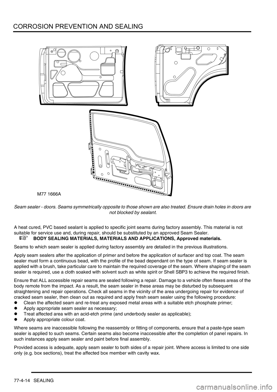
Seam sealer - doors. Seams symmetrically opposite to those shown are also treated. Ensure drain holes in doors are
not blocked by sealant.
A heat cured, PVC based sealant is applied to specific joint seams during factory assembly. This material is not
suitable for service use and, during repair, should be substituted by an approved Seam Sealer.
+ BODY SEALING MATERIALS, MATERIALS AND APPLICATIONS, Approved materials.
Seams to which seam sealer is applied during factory assembly are detailed in the previous illustrations.
Apply seam sealers after the application of primer and before the application of surfacer and top coat. The seam
sealer must form a continuous bead, with the profile of the bead dependant on the type of seam. If seam sealer is
applied with a brush, take particular care to maintain the required coverage of the seam. Where shaping of the seam
sealer is required, use a cloth soaked with solvent such as white spirit or Shell SBP3 to achieve the required finish.
Ensure that ALL accessible repair seams are sealed following a repair. Damage to a vehicle often flexes areas of the
body remote from the impact. As a result, the seam sealer in these areas may be disturbed by subsequent
straightening and repair operations. Check all seams in the vicinity of the area undergoing repair for evidence of
cracked seam sealer, then clean out as required and apply fresh seam sealer using the following procedure:
lClean the affected seam and re-treat any exposed metal areas with a suitable etch phosphate primer;
lApply appropriate seam sealer as necessary;
lTreat affected area with an acid-etch prime (and underbody sealer as applicable);
lApply appropriate colour coat.
Where seams are inaccessible following the reassembly or fitting of components, ensure that a paste-type seam
sealer is applied to such seams. Certain seams also become inaccessible after the completion of panel repairs. In
such instances apply seam sealer and paint before final assembly.
Provided access is adequate, apply seam sealer to both sides of a repair joint. Where access is limited to one side
only (e.g. box sections), treat the affected box member with cavity wax.
M77 1666A
Page 1355 of 1672

HEATING AND VENTILATION
80-14DESCRIPTION AND OPERATION
Coolant temperature control
When the ECU first enters the active mode, it initiates a start to full load combustion. Full load combustion continues
until the heat exchanger casing temperature reaches 60
°C (140 °F), when the ECU decreases the speed of the FBH
fuel pump and the combustion air fan to half speed, to produce part load combustion. The ECU maintains part load
combustion while the heat exchanger casing temperature remains between 54 and 65
°C (129 and 149 °F). If the heat
exchanger casing temperature decreases to 54
°C (129 °F), the ECU switches the system to full load combustion
again. If the heat exchanger casing temperature increases to 65
°C (149 °F), the ECU enters a control idle phase of
operation.
On entering the control idle phase, the ECU immediately switches the FBH fuel pump off, to stop combustion, and
starts a timer for the combustion air fan. After a 2 minute cooldown period, the ECU switches the combustion air fan
off and then remains in the control idle phase while the heat exchanger casing temperature remains above 59
°C (138
°F). If the heat exchanger casing temperature decreases to 59 °C (138 °F), within 15 minutes of the ECU entering the
control idle phase, the ECU initiates a start to part load combustion. If more than 15 minutes elapse before the heat
exchanger casing temperature decreases to 59
°C (138 °F), the ECU initiates a start to full load combustion.
In order to limit the build-up of carbon deposits on the glow plug/flame sensor, the ECU also enters the control idle
phase if the continuous part and/or full load combustion time exceeds 72 minutes. After the cooldown period, if the
heat exchanger casing is still in the temperature range that requires additional heat, the ECU initiates an immediate
restart to part or full load combustion, as appropriate.
Shutdown
The FBH system is de-activated when the alternator power supply to the FBH unit is disconnected, either by the
engine stopping or, if the ambient temperature increases to 5
°C (41 °F) or above, by the contacts in the air
temperature sensor opening. If the system is active when the alternator power supply is disconnected, the ECU de-
energises the FBH fuel pump to stop combustion, but continues operation of the combustion air fan and the circulation
pump to cool down the FBH unit. The cool down time depends on the combustion load at the time the alternator power
input is disconnected.
Cool down times
Diagnostics
The ECU in the FBH unit monitors the system for faults. Any faults detected are stored in a volatile memory in the the
ECU, which can be interrogated by Testbook. A maximum of three faults and associated freeze frame data can be
stored at any one time. If a further fault is detected, the oldest fault is overwritten by the new fault.
The ECU also incorporates an error lockout mode of operation that inhibits system operation to prevent serious faults
from causing further damage to the system. In the error lockout mode, the ECU immediately stops the FBH fuel pump,
and stops the combustion air fan and circulation pump after a cool down time of approximately 2 minutes. Error lockout
occurs for start sequence failures and/or combustion flameouts, heat exchanger casing overheat and out of limit input
voltage. The error lockout mode can be cleared using Testbook, or by disconnecting the battery power supply for a
minimum of 10 seconds.
Start failure/flameout. If a start sequence fails to establish combustion, or a flameout occurs after combustion is
established, the ECU immediately initiates another start sequence. The start failure or flameout is also recorded by
an event timer in the ECU. The event timer is increased by one after each start failure or flameout, and decreased by
one if a subsequent start is successful. If the event timer increases to three (over any number of drive cycles), the
ECU enters the error lockout mode.
Heat exchanger casing overheat. To protect the system from excessive temperatures, the ECU enters the error
lockout mode if the heat exchanger casing temperature exceeds 105
°C (221 °F).
Out of limit voltage. The ECU enters the error lockout mode if the battery or alternator power input is less than 10.5
±
0.3 V for more than 20 seconds, or more than 15.5
± 0.5 V for more than 6 seconds.
Combustion load Cool down time, seconds
Part 100
Full 175
Page 1361 of 1672
HEATING AND VENTILATION
80-20REPAIRS
Servo - air temperature control
$% 80.10.42
Remove
1.Disconnect battery earth lead.
2. Driver side: Remove heater assembly.
+ HEATING AND VENTILATION,
REPAIRS, Heater assembly - models with
air conditioning.
3. Passenger side: Remove blower assembly.
+ HEATING AND VENTILATION,
REPAIRS, Blower assembly.
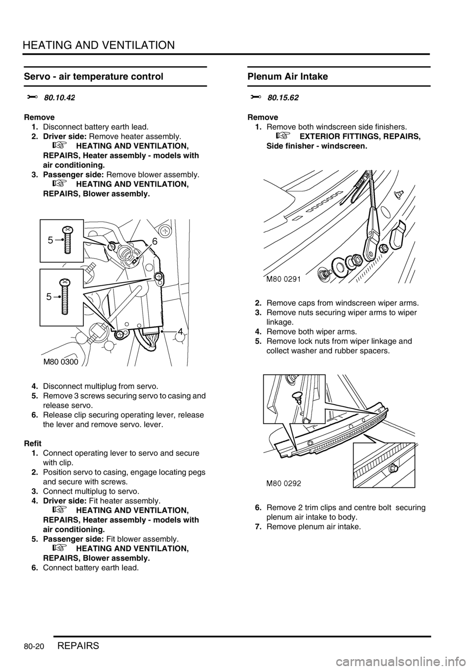
4.Disconnect multiplug from servo.
5.Remove 3 screws securing servo to casing and
release servo.
6.Release clip securing operating lever, release
the lever and remove servo. lever.
Refit
1.Connect operating lever to servo and secure
with clip.
2.Position servo to casing, engage locating pegs
and secure with screws.
3.Connect multiplug to servo.
4. Driver side: Fit heater assembly.
+ HEATING AND VENTILATION,
REPAIRS, Heater assembly - models with
air conditioning.
5. Passenger side: Fit blower assembly.
+ HEATING AND VENTILATION,
REPAIRS, Blower assembly.
6.Connect battery earth lead.
Plenum Air Intake
$% 80.15.62
Remove
1.Remove both windscreen side finishers.
+ EXTERIOR FITTINGS, REPAIRS,
Side finisher - windscreen.
2.Remove caps from windscreen wiper arms.
3.Remove nuts securing wiper arms to wiper
linkage.
4.Remove both wiper arms.
5.Remove lock nuts from wiper linkage and
collect washer and rubber spacers.
6.Remove 2 trim clips and centre bolt securing
plenum air intake to body.
7.Remove plenum air intake.
Page 1362 of 1672
HEATING AND VENTILATION
REPAIRS 80-21
Refit
1.Fit plenum air intake.
2.Fit trim clips and centre bolt securing plenum
air intake to body.
3.Fit rubber spacers and washers to wiper
linkage.
4.Fit locknuts to wiper linkage and tighten to 7
Nm (5.2 lbf.ft).
5.Fit wiper arms to wiper linkage.
6.Fit nuts securing wiper arms to wiper linkage
and tighten to 15 Nm (11 lbf.ft).
7.Fit caps to wiper arms.
8.Fit both windscreen side finishers.
+ EXTERIOR FITTINGS, REPAIRS,
Side finisher - windscreen.
Heater assembly - models without air
conditioning
$% 80.20.01.99
Remove
1.Drain cooling system.
l
+ COOLING SYSTEM - Td5,
ADJUSTMENTS, Drain and refill.
l
+ COOLING SYSTEM - V8,
ADJUSTMENTS, Drain and refill.
2. Diesel models: Remove 3 bolts and remove
engine cover.
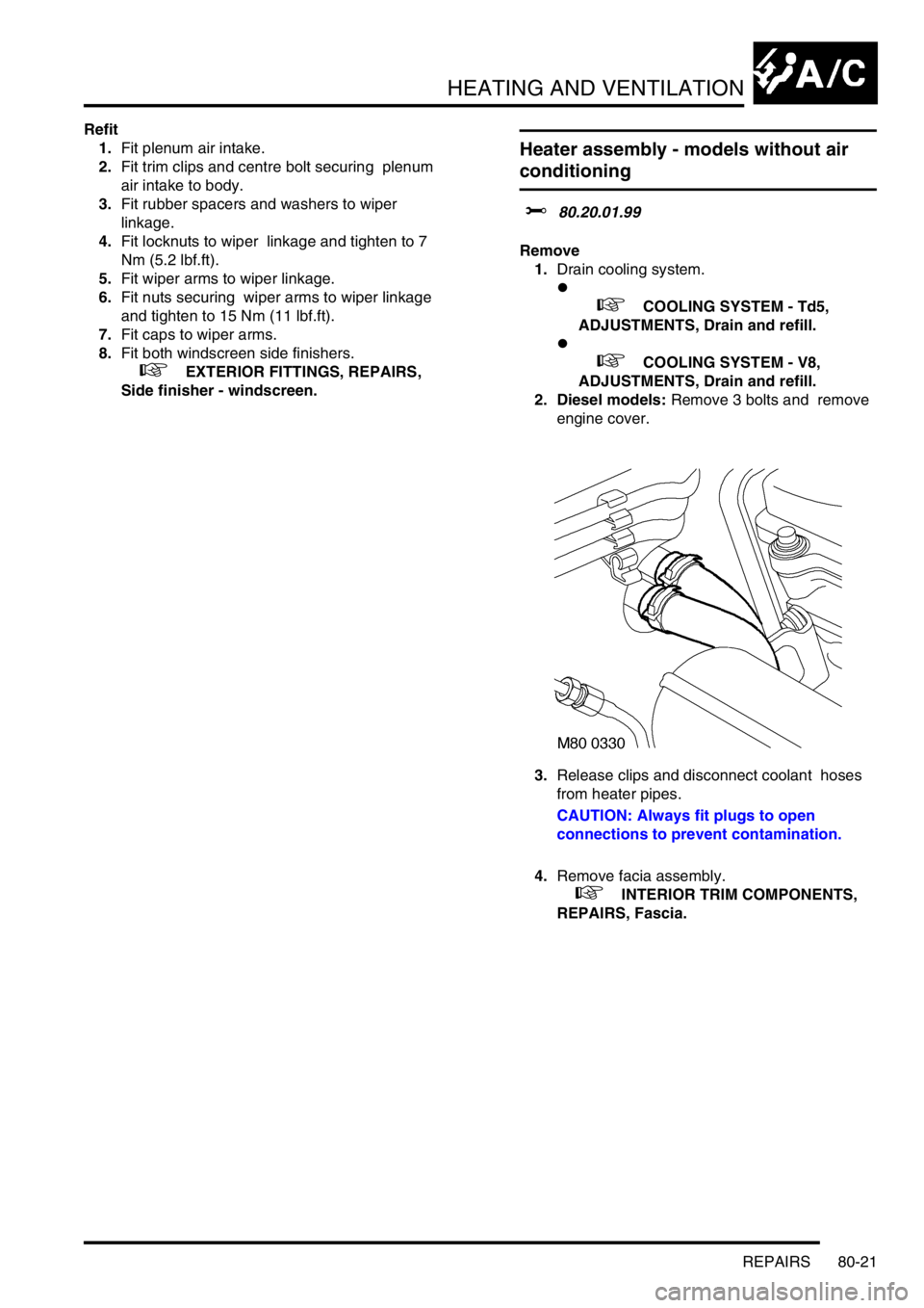
3.Release clips and disconnect coolant hoses
from heater pipes.
CAUTION: Always fit plugs to open
connections to prevent contamination.
4.Remove facia assembly.
+ INTERIOR TRIM COMPONENTS,
REPAIRS, Fascia.
Page 1371 of 1672
HEATING AND VENTILATION
80-30REPAIRS
Refit
1.Connect engine coolant hose to heater return
pipe and secure with clip.
2.Position heater return pipe to cylinder block and
secure with bolt.
3.Secure engine harness and vacuum pipe to
heater return pipe and secure with clips.
4.Fit and tighten bolt securing heater return pipe
to heater feed pipe.
5.Connect heater return hose to heater return
pipe and secure with clip.
6.Refill engine coolant.
+ COOLING SYSTEM - V8,
ADJUSTMENTS, Drain and refill.
Fuel burning heater - (FBH) - Td5
$% 80.40.01.99
Remove
1.Release fixings and remove battery cover.
2.Disconnect battery earth lead.
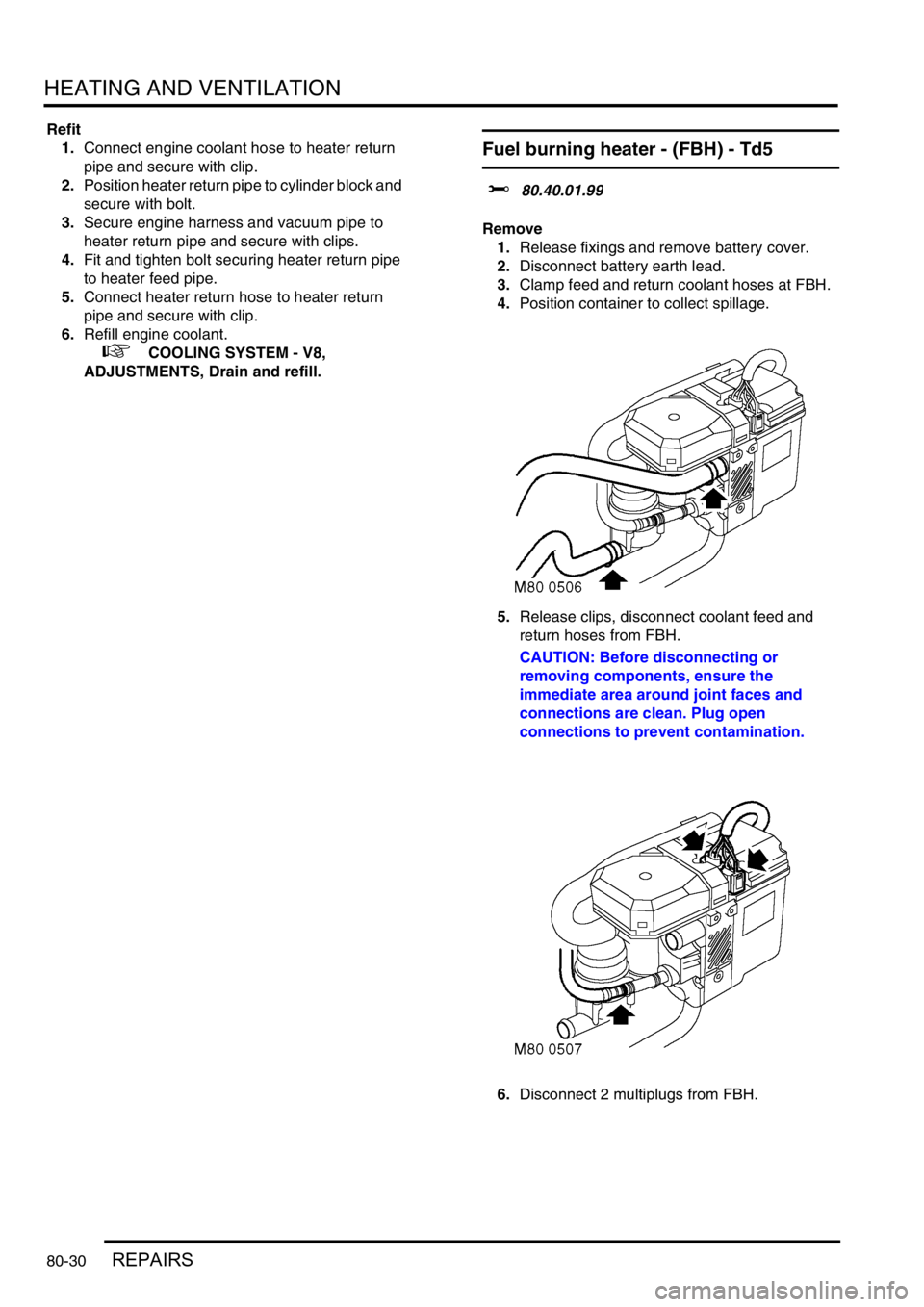
3.Clamp feed and return coolant hoses at FBH.
4.Position container to collect spillage.
5.Release clips, disconnect coolant feed and
return hoses from FBH.
CAUTION: Before disconnecting or
removing components, ensure the
immediate area around joint faces and
connections are clean. Plug open
connections to prevent contamination.
6.Disconnect 2 multiplugs from FBH.