2002 LAND ROVER DISCOVERY radio antenna
[x] Cancel search: radio antennaPage 1617 of 1672

NAVIGATION SYSTEM
87-2 DESCRIPTION AND OPERATION
Description
General
The navigation system provides audio and visual route guidance to help the driver reach a selected destination. The
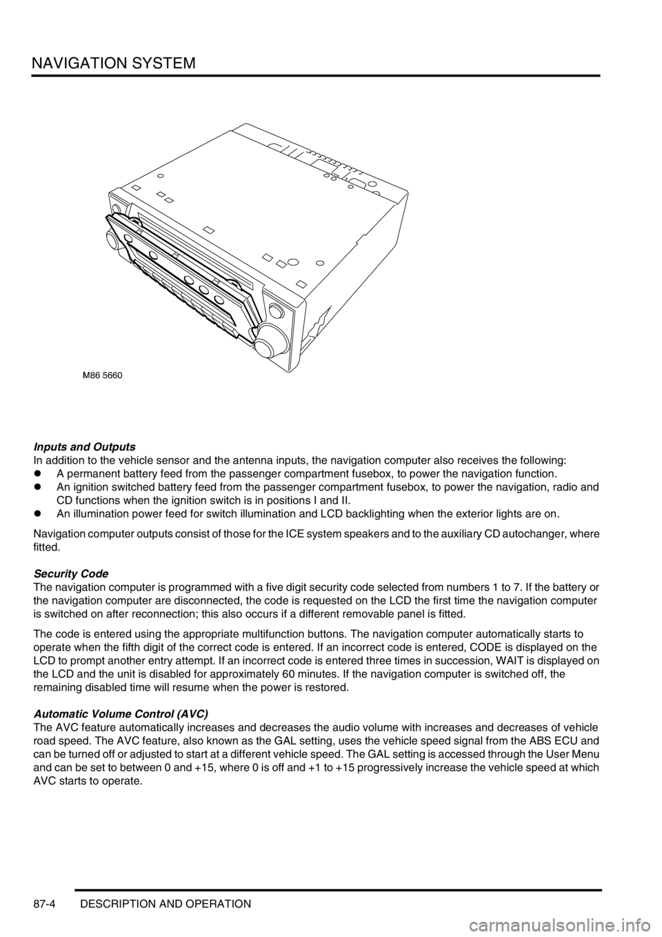
system is an optional fit consisting of a Traffic Pro navigation computer and antenna, manufactured by Harman/
Becker Automotive Systems, which are fitted in place of the In Car Entertainment (ICE) head unit and antenna.
Compact Disc (CD) and radio functions are incorporated into the navigation computer.
The navigation system allows the driver to choose between the shortest and fastest routes between the vehicle's
current position and a selected destination, and to select a stopover point in the journey and a route that avoids
motorways, ferries and toll roads. Directions to Points Of Interest (POI) e.g. airports, hospitals, petrol stations etc,
either local, national or in another country, can also be selected. A traffic jam function enables the driver to request
diversion instructions, around an obstructed part of the selected route, during the journey. A Traffic Management
Control (TMC) function, currently only available in some European countries, monitors traffic broadcasts and
automatically selects an alternative route during the journey if the original route is effected by a traffic jam, accident
or road works etc.
The position of the vehicle is determined by the navigation computer using a combination of vehicle sensor inputs and
radio signals from the 24 Global Positioning System (GPS) satellites orbiting the earth. The position of the vehicle is
then plotted on a digitised map, loaded into the navigation computer from a CD-ROM, to determine the journey route
and provide the route guidance.
The GPS satellite signals are used for initial determination of the vehicle's position and periodic position updates. The
vehicle sensor inputs are used to monitor the vehicle's direction of travel and distance travelled between position
updates from the GPS satellite signals. The vehicle sensor inputs consist of:
lA vehicle speed signal from the ABS ECU, to monitor the distance travelled and for automatic volume control.
lA reverse gear signal from the selector and inhibitor switch of the automatic gearbox, or reverse gear switch of
the manual gearbox, to enable the navigation computer to differentiate between forward and rearward movement
of the vehicle.
lA gyro in the navigation computer, to monitor changes of direction, i.e. steering inputs.
The signal from each GPS satellite contains information about satellite position, almanac data and time (almanac data
is the current status of the satellite). Signals from between five and 11 of the GPS satellites can be received at a given
point on the earth's surface at any one time. The number and quality of separate GPS satellite signals received also
varies with vehicle location. In hilly or tree lined areas, built up areas with tall buildings, multi-storey car parks,
garages, tunnels, bridges and during heavy rain/thunderstorms, signal reception of some or all of the GPS satellites
will be poor or non existent.
A minimum of three separate GPS satellite signals are required for the navigation computer to calculate a three
dimensional (3D) positional fix. When only two signals are being received, the navigation computer will calculate a
less accurate two dimensional (2D) positional fix. The more widely dispersed that the GPS satellites are, the more
accurate the positional fix. The navigation computer can store information from a maximum of 12 GPS satellites at
any one time. When more than three signals are stored, the navigation computer selects the three most widely
dispersed signals for the position calculation.
GPS Antenna and diplexer unit
The GPS antenna is installed at the rear of the roof on the centreline. A diplexer unit on the underside of the GPS
antenna amplifies the radio signals received from the GPS satellites and transmits them through separate dedicated
co-axial cable to the navigation computer for processing.
Page 1619 of 1672

NAVIGATION SYSTEM
87-4 DESCRIPTION AND OPERATION
Inputs and Outputs
In addition to the vehicle sensor and the antenna inputs, the navigation computer also receives the following:
lA permanent battery feed from the passenger compartment fusebox, to power the navigation function.
lAn ignition switched battery feed from the passenger compartment fusebox, to power the navigation, radio and
CD functions when the ignition switch is in positions I and II.
lAn illumination power feed for switch illumination and LCD backlighting when the exterior lights are on.
Navigation computer outputs consist of those for the ICE system speakers and to the auxiliary CD autochanger, where
fitted.
Security Code
The navigation computer is programmed with a five digit security code selected from numbers 1 to 7. If the battery or
the navigation computer are disconnected, the code is requested on the LCD the first time the navigation computer
is switched on after reconnection; this also occurs if a different removable panel is fitted.
The code is entered using the appropriate multifunction buttons. The navigation computer automatically starts to
operate when the fifth digit of the correct code is entered. If an incorrect code is entered, CODE is displayed on the
LCD to prompt another entry attempt. If an incorrect code is entered three times in succession, WAIT is displayed on
the LCD and the unit is disabled for approximately 60 minutes. If the navigation computer is switched off, the
remaining disabled time will resume when the power is restored.
Automatic Volume Control (AVC)
The AVC feature automatically increases and decreases the audio volume with increases and decreases of vehicle
road speed. The AVC feature, also known as the GAL setting, uses the vehicle speed signal from the ABS ECU and
can be turned off or adjusted to start at a different vehicle speed. The GAL setting is accessed through the User Menu
and can be set to between 0 and +15, where 0 is off and +1 to +15 progressively increase the vehicle speed at which
AVC starts to operate.
Page 1621 of 1672

NAVIGATION SYSTEM
87-6 DESCRIPTION AND OPERATION
Service Menu
The service menu provides access to details of the navigation computer hardware and software, and can be accessed
when the navigation computer is in radio mode, by simultaneously pressing the NAV button and the 10 multifunction
buttons. The following items can then be scrolled through by pressing the Nxt (next) and Prv (previous) multifunction
buttons, or turning the RH rotary control:
lModel No.
lSerial No.
lChanger Reset
lGAL
lRadio Software
lRadio Bolo
lNavi Rom
lNavi Flash
lRTC Value
When Changer Reset is displayed, the CD autochanger (where fitted) can be reset by pressing the appropriate
multifunction button.
When the End multifunction button is pressed, the navigation computer quits the service menu and returns to radio
mode.
Garage Menu
Garage menu enables the navigation system to be tested and calibrated, and also contains a route navigation
demonstration. The garage menu is entered from the main navigation menu, as follows:
1Press the Nav button to access the system settings.
2Press and hold multifunction button 3, then press multifunction button 5 to display the garage menu.
The garage menu contains the following, which can be accessed using the RH rotary control:
lCALIBRATION RIDE – Used to calibrate the navigation computer, to enable route navigation.
lGPS INFO– Provides functional test of antenna by checking GPS reception. If functioning correctly, displays the
number of satellites being received, the date, time (Greenwich Mean Time) and the type of positional fix currently
possible.
lCALIBRATION– Allows vehicle specific calibration data to be entered, e.g. tyre size. Also allows current
calibration to be deleted prior to re-calibrating.
NOTE: Only known calibration data should be entered. The navigation computer cannot make route
calculations if incorrect data is entered.
lSENSORS– Allows wheel speed, reverse gear and gyro sensor inputs to be checked.
lVERSION– Displays navigation computer hardware and software details.
lSPEECH TEST– Performs a test of the navigation computer audio output.
lMODULE TEST– Performs a test routine on the internal components of the navigation computer.
lDEMO – Allows a route navigation demonstration to be run.
To quit the garage menu, press the Nav button.
Calibration
Calibration is required after initial installation or replacement of the navigation computer. It may also be necessary
after repairs to system wiring and if route navigation becomes inaccurate or fails to operate. If the navigation computer
contains an existing calibration, this must be deleted, using the garage menu, prior to running the new calibration
routine. The sensor inputs should also be checked before running the calibration routine.