2002 LAND ROVER DISCOVERY wiper fluid
[x] Cancel search: wiper fluidPage 5 of 1672

CONTENTS
2CONTENTS
IDENTIFICATION NUMBERS .................................................................. 05-1
Vehicle Identification Number ......................................................................................................... 05-1
Identification Number Locations ..................................................................................................... 05-3
TORQUE WRENCH SETTINGS .............................................................. 06-1
Maintenance ................................................................................................................................... 06-1
Engine Td5 ..................................................................................................................................... 06-2
Engine V8 ....................................................................................................................................... 06-4
Emission control - Td5 .................................................................................................................... 06-5
Emission control - V8 ...................................................................................................................... 06-5
Engine management system - Td5 ................................................................................................. 06-5
Engine management system - V8................................................................................................... 06-6
Cooling system ............................................................................................................................... 06-6
Manifolds and exhaust systems - Td5 ............................................................................................ 06-6
Manifolds and exhaust systems - V8 .............................................................................................. 06-7
Clutch.............................................................................................................................................. 06-7
Manual gearbox - R380 .................................................................................................................. 06-8
Transfer box - LT230SE ................................................................................................................. 06-8
Automatic gearbox - ZF4HP22/24 .................................................................................................. 06-9
Propeller shafts ............................................................................................................................... 06-9
Axles ............................................................................................................................................... 06-9
Steering .......................................................................................................................................... 06-10
Front suspension ............................................................................................................................ 06-11
Rear suspension ............................................................................................................................. 06-12
Brakes............................................................................................................................................. 06-12
Restraint systems ........................................................................................................................... 06-13
Body................................................................................................................................................ 06-14
Heating and air conditioning ........................................................................................................... 06-15
Wipers and washers ....................................................................................................................... 06-15
Electrical ......................................................................................................................................... 06-15
LIFTING AND TOWING ........................................................................... 08-1
LIFTING .......................................................................................................................................... 08-1
TOWING ......................................................................................................................................... 08-2
TRANSPORTING ........................................................................................................................... 08-3
CAPACITIES, FLUIDS AND LUBRICANTS ............................................ 09-1
Capacities ....................................................................................................................................... 09-1
Fluids .............................................................................................................................................. 09-2
Anti-Freeze Concentration .............................................................................................................. 09-3
Lubrication ...................................................................................................................................... 09-3
MAINTENANCE ........................................................................................ 10-1
PROCEDURES
V8 engine underbonnet view .......................................................................................................... 10-1
Diesel underbonnet view ................................................................................................................ 10-2
Seats and seat belts ...................................................................................................................... 10-3
Lamps, horns and warning indicators ........................................................................................... 10-5
Wipers and washers ...................................................................................................................... 10-5
Handbrake .................................................................................................................................. 10-6
Page 943 of 1672

FRONT SUSPENSION
60-4 DESCRIPTION AND OPERATION
Description
General
The front suspension comprises two dampers and coil springs, two radius arms, a Panhard rod and an anti-roll bar.
The front axle provides the location points for the dampers, springs, radius arms and the Panhard rod.
The anti-roll bar assembly is an essential part of the front suspension. On vehicles without Active Cornering
Enhancement (ACE) a conventional 'passive' anti-roll bar is fitted. On vehicles fitted with the ACE system, a thicker
diameter anti-roll bar, known as a torsion bar, is used with an actuator at one end.
+ FRONT SUSPENSION, DESCRIPTION AND OPERATION, Description - ACE.
The hydraulic dampers and coil springs provide springing for each front wheel. The long travel dampers, springs and
radius arms provide maximum axle articulation and wheel travel for off-road driving. The front axle is controlled
longitudinally by two forged steel radius arms and transversely by a Panhard rod.
Radius arms
Each radius arm is manufactured from forged steel. Two bushes are pressed into the forward end of the radius arm.
The forward end of the radius arm is located in a fabricated bracket on the axle and secured through the bushes with
two bolts and nuts. A bush is pressed into the rear of the radius arm which is also located in a fabricated bracket on
each chassis longitudinal and secured through the bush with a bolt and nut.
The radius arms prevent longitudinal movement of the front axle and because of their length allow maximum axle
articulation. The stiffness of the bushes in each radius arm also contributes to the vehicle roll stiffness.
Each radius arm has a notch on its lower edge which provides location for the vehicle jack.
Dampers
Two conventional telescopic dampers are used to control body/axle movement. A turret is located on a bracket welded
to the chassis. The upper spring seat has four studs which pass through holes in the bracket and align with
corresponding holes in the turret. Four nuts are screwed onto the studs and secure the turret and upper spring seat
to the chassis.
A fabricated platform is welded to the axle. The platform has two captive nuts which provide for the attachment of the
damper. A lower spring seat is located on the platform. Each spring seat is handed and has a bracket which secures
the ABS sensor harness and the front brake hose.
Each damper is fitted with a bush at its upper end. The bush locates in the top of the turret and is secured with a cross
bolt. The lower attachment point for the damper is also fitted with a bush. This bush has a spindle through its centre
with a hole at each end. The spindle is seated on the lower spring seat and the axle platform and secured with two
bolts. The coil spring is fitted in a compressed state between the upper and lower spring seats and assists the damper
in controlling the body/axle movement. The upper and lower bushes are replaceable items.
Rubber bump stops are fitted to the chassis above each end of the axle. The bump stops are progressive in their
compression and prevent the axle from contacting the chassis in the event of maximum suspension travel being
reached. The bump stops revert to their original shape once the compression load has been removed from them.
The damper functions by restricting the flow of a hydraulic fluid through internal galleries within the damper body. A
chromium plated rod moves axially within the damper. As the rod moves, its movement is limited by the flow of fluid
through the galleries thus providing damping of undulations in the terrain. The damper rod is sealed at its exit point
from the body to maintain fluid within the unit and prevent the ingress of dirt and moisture. The seal also acts as a
wiper to keep the rod outer diameter clean. A plastic shroud protects the rod and slides over the body as the damper
moves. The coil spring aids the damper to extend after being compressed and also aids the damping process.
Page 1270 of 1672
PANEL REPAIRS
REPAIRS 77-2-21
REPAIRS
Front bulkhead assembly
Remove
1.Disconnect both battery leads, negative lead
first.
2.Disconnect leads/multiplug from alternator.
3.Remove front wing.
+ EXTERIOR FITTINGS, REPAIRS,
Wing - front - up to 03MY.
4.Remove washer reservoir.
+ WIPERS AND WASHERS, REPAIRS,
Reservoir - washer - up to 03MY.
5. Models with A/C: Remove condensor.
+ AIR CONDITIONING, REPAIRS,
Condenser.
6. Diesel models: Remove gearbox fluid cooler.
7.Remove RH and LH headlamps.
+ LIGHTING, REPAIRS, Headlamp - up
to 03MY.
8.Release headlamp levelling motors and
position aside.
9.Release headlamp wiring and position aside.
10.Remove battery.
+ CHARGING AND STARTING,
REPAIRS, Battery.
11.Remove battery tray.
12.Remove air filter assembly.
+ ENGINE MANAGEMENT SYSTEM -
Td5, REPAIRS, Air filter assembly.
+ ENGINE MANAGEMENT SYSTEM -
V8, REPAIRS, Air cleaner assembly.
13.Remove 2 earth leads from LH of front
bulkhead.
14.Remove RH horn.
+ ALARM SYSTEM AND HORN,
REPAIR, Vehicle horn.
15. Models with A/C: Release and remove A/C
pipes.
16.Remove RH and LH crush cans.
17.Remove bonnet release cable.
18.Support bonnet in open position
19.Remove bonnet locking mechanism.
20.Remove VIN plate.
21.Remove 2 bolts securing front bulkhead
assembly to chassis.
22.Remove centre braces.Repair
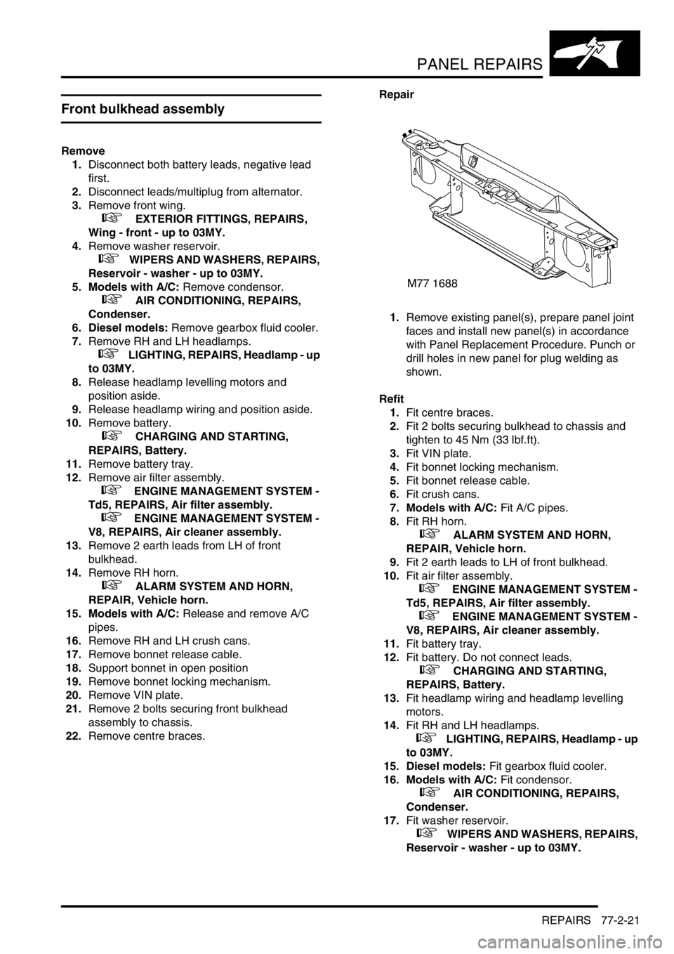
1.Remove existing panel(s), prepare panel joint
faces and install new panel(s) in accordance
with Panel Replacement Procedure. Punch or
drill holes in new panel for plug welding as
shown.
Refit
1.Fit centre braces.
2.Fit 2 bolts securing bulkhead to chassis and
tighten to 45 Nm (33 lbf.ft).
3.Fit VIN plate.
4.Fit bonnet locking mechanism.
5.Fit bonnet release cable.
6.Fit crush cans.
7. Models with A/C: Fit A/C pipes.
8.Fit RH horn.
+ ALARM SYSTEM AND HORN,
REPAIR, Vehicle horn.
9.Fit 2 earth leads to LH of front bulkhead.
10.Fit air filter assembly.
+ ENGINE MANAGEMENT SYSTEM -
Td5, REPAIRS, Air filter assembly.
+ ENGINE MANAGEMENT SYSTEM -
V8, REPAIRS, Air cleaner assembly.
11.Fit battery tray.
12.Fit battery. Do not connect leads.
+ CHARGING AND STARTING,
REPAIRS, Battery.
13.Fit headlamp wiring and headlamp levelling
motors.
14.Fit RH and LH headlamps.
+ LIGHTING, REPAIRS, Headlamp - up
to 03MY.
15. Diesel models: Fit gearbox fluid cooler.
16. Models with A/C: Fit condensor.
+ AIR CONDITIONING, REPAIRS,
Condenser.
17.Fit washer reservoir.
+ WIPERS AND WASHERS, REPAIRS,
Reservoir - washer - up to 03MY.
Page 1272 of 1672
PANEL REPAIRS
REPAIRS 77-2-23
Repair
1.Remove existing panel(s), prepare panel joint
faces and install new panel(s) in accordance
with Panel Replacement Procedure. Punch or
drill holes in new panel for plug welding as
shown.
Refit
1.Fit centre braces.
2.Fit VIN plate.
3.Fit bonnet locking mechanism.
4.Fit bonnet release cable.
5.Fit RH horn.
+ ALARM SYSTEM AND HORN,
REPAIR, Vehicle horn.
6.Fit air filter assembly.
+ ENGINE MANAGEMENT SYSTEM -
Td5, REPAIRS, Air filter assembly.
+ ENGINE MANAGEMENT SYSTEM -
V8, REPAIRS, Air cleaner assembly.
7.Fit battery tray.
8.Fit battery. Do not connect leads.
+ CHARGING AND STARTING,
REPAIRS, Battery.
9.Fit headlamp wiring.
10.Fit RH and LH repeater lamps.
+ LIGHTING, REPAIRS, Lamp - front
repeater.
11.Fit RH and LH headlamps.
+ LIGHTING, REPAIRS, Headlamp - up
to 03MY.
12. Diesel models: Fit gearbox fluid cooler.
13. Models with A/C: Fit condensor.
+ AIR CONDITIONING, REPAIRS,
Condenser.
14.Fit bumper assembly.
+ EXTERIOR FITTINGS, REPAIRS,
Bumper assembly - front.
15.Connect leads/multiplug to alternator.
16.Connect battery leads, negative lead last.
Front cross member
Remove
1.Disconnect both battery leads, negative lead
first.
2.Disconnect leads/multiplug from alternator.
3.Remove washer reservoir.
+ WIPERS AND WASHERS, REPAIRS,
Reservoir - washer - up to 03MY.
4. Models with A/C: Remove condensor.
+ AIR CONDITIONING, REPAIRS,
Condenser.
5. Diesel models: Remove gearbox fluid cooler.
6.Remove RH and LH headlamps.
+ LIGHTING, REPAIRS, Headlamp - up
to 03MY.
7.Release headlamp levelling motors and
position aside.
8.Release headlamp wiring and position aside.
9.Remove RH horn.
+ ALARM SYSTEM AND HORN,
REPAIR, Vehicle horn.
10. Models with A/C: Release and remove A/C
pipes.
11.Remove RH and LH crush cans.
12.Remove 2 bolts securing front bulkhead
assembly to chassis.
13.Remove centre braces.
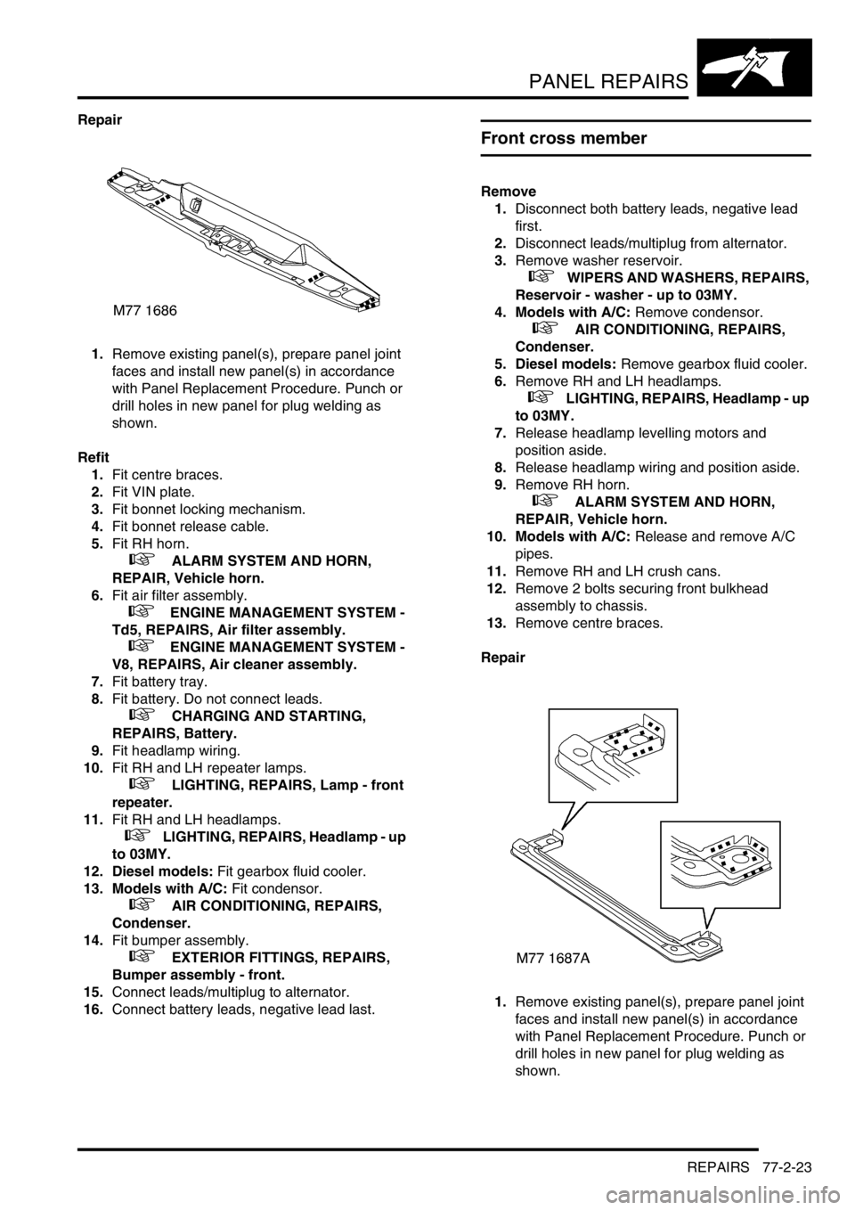
Repair
1.Remove existing panel(s), prepare panel joint
faces and install new panel(s) in accordance
with Panel Replacement Procedure. Punch or
drill holes in new panel for plug welding as
shown.
Page 1273 of 1672
PANEL REPAIRS
77-2-24 REPAIRS
Refit
1.Fit centre braces.
2.Fit 2 bolts securing bulkhead to chassis and
tighten bolts to 45 Nm (33 lbf.ft).
3.Fit crush cans.
4. Models with A/C: Fit A/C pipes.
5.Fit RH horn.
+ ALARM SYSTEM AND HORN,
REPAIR, Vehicle horn.
6.Fit headlamp wiring and headlamp levelling
motors.
7.Fit RH and LH headlamps.
+ LIGHTING, REPAIRS, Headlamp - up
to 03MY.
8. Diesel models: Fit gearbox fluid cooler.
9. Models with A/C: Fit condensor.
+ AIR CONDITIONING, REPAIRS,
Condenser.
10.Fit washer reservoir.
+ WIPERS AND WASHERS, REPAIRS,
Reservoir - washer - up to 03MY.
11.Connect leads/multiplug to alternator.
12.Connect battery leads, negative lead last.
Headlamp mounting panel - RH
Remove
1.Disconnect both battery leads, negative lead
first.
2.Disconnect leads/multiplug from alternator.
3.Remove front bumper assembly.
+ EXTERIOR FITTINGS, REPAIRS,
Bumper assembly - front.
4. Models with A/C: Remove condensor.
+ AIR CONDITIONING, REPAIRS,
Condenser.
5. Diesel models: Remove gearbox fluid cooler.
6.Remove RH headlamp.
+ LIGHTING, REPAIRS, Headlamp - up
to 03MY.
7.Remove RH repeater lamp.
+ LIGHTING, REPAIRS, Lamp - front
repeater.
8.Release headlamp levelling motor and position
aside.
9.Release headlamp wiring and position aside.
10.Remove battery and battery tray.
+ CHARGING AND STARTING,
REPAIRS, Battery.
11.Remove horn.
+ ALARM SYSTEM AND HORN,
REPAIR, Vehicle horn.
12.Remove RH crush can.
13.Remove 2 bolts securing front bulkhead
assembly to chassis.
14.Remove RH centre brace.
Page 1275 of 1672
PANEL REPAIRS
77-2-26 REPAIRS
Headlamp mounting panel - LH
Remove
1.Disconnect both battery leads, negative lead
first.
2.Disconnect leads/multiplug from alternator.
3.Remove washer reservoir.
+ WIPERS AND WASHERS, REPAIRS,
Reservoir - washer - up to 03MY.
4. Models with A/C: Remove condensor.
+ AIR CONDITIONING, REPAIRS,
Condenser.
5. Diesel models: Remove gearbox fluid cooler.
6.Remove headlamp.
+ LIGHTING, REPAIRS, Headlamp - up
to 03MY.
7.Remove repeater lamp.
+ LIGHTING, REPAIRS, Lamp - front
repeater.
8.Release headlamp levelling motor and position
aside.
9.Release headlamp wiring and position aside.
10.Remove air filter assembly.
+ ENGINE MANAGEMENT SYSTEM -
Td5, REPAIRS, Air filter assembly.
+ ENGINE MANAGEMENT SYSTEM -
V8, REPAIRS, Air cleaner assembly.
11.Remove 2 earth leads from LH of front
bulkhead.
12.Release and remove A/C pipes.
13.Remove crush can.
14.Remove bonnet release cable.
15.Remove 2 bolts securing front bulkhead
assembly to chassis.
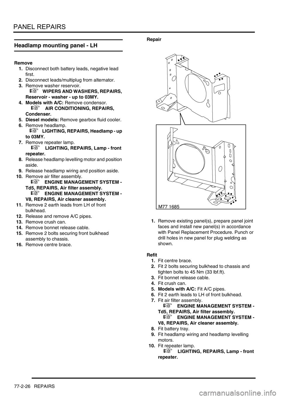
16.Remove centre brace.Repair
1.Remove existing panel(s), prepare panel joint
faces and install new panel(s) in accordance
with Panel Replacement Procedure. Punch or
drill holes in new panel for plug welding as
shown.
Refit
1.Fit centre brace.
2.Fit 2 bolts securing bulkhead to chassis and
tighten bolts to 45 Nm (33 lbf.ft).
3.Fit bonnet release cable.
4.Fit crush can.
5. Models with A/C: Fit A/C pipes.
6.Fit 2 earth leads to LH of front bulkhead.
7.Fit air filter assembly.
+ ENGINE MANAGEMENT SYSTEM -
Td5, REPAIRS, Air filter assembly.
+ ENGINE MANAGEMENT SYSTEM -
V8, REPAIRS, Air cleaner assembly.
8.Fit battery tray.
9.Fit headlamp wiring and headlamp levelling
motors.
10.Fit repeater lamp.
+ LIGHTING, REPAIRS, Lamp - front
repeater.
Page 1276 of 1672
PANEL REPAIRS
REPAIRS 77-2-27
11.Fit headlamp.
+ LIGHTING, REPAIRS, Headlamp - up
to 03MY.
12. Diesel models: Fit gearbox fluid cooler.
13. Models with A/C: Fit condensor.
+ AIR CONDITIONING, REPAIRS,
Condenser.
14.Fit washer reservoir.
+ WIPERS AND WASHERS, REPAIRS,
Reservoir - washer - up to 03MY.
15.Connect leads/multiplug to alternator.
16.Connect battery leads, negative lead last.
Valance upper assembly - LH
In this procedure, the front wing, the valance outer
reinforcement and the bonnet alarm switch mounting
bracket are replaced in conjunction with the LH
valance upper assembly.
Remove
1.Disconnect both battery leads, negative lead
first.
2.Disconnect leads/multiplug from alternator.
3.Remove front wing.
+ EXTERIOR FITTINGS, REPAIRS,
Wing - front - up to 03MY.
4.Remove air filter assembly.
+ ENGINE MANAGEMENT SYSTEM -
V8, REPAIRS, Air cleaner assembly.
+ ENGINE MANAGEMENT SYSTEM -
Td5, REPAIRS, Air filter assembly.
5.Remove PAS/ACE reservoir.
6.Remove ABS modulator.
+ BRAKES, REPAIRS, Modulator unit
- ABS.
7.Remove brake pipes from valance.
8.Release harness from valance and position
aside.
9. Models with A/C: Depressurise A/C system
and remove pipes from valance.
+ AIR CONDITIONING, REFRIGERANT
RECOVERY, RECYCLING AND
RECHARGING, Refrigerant recovery,
recycling and recharging.
Page 1429 of 1672
WIPERS AND WASHERS
84-8 DESCRIPTION AND OPERATION
Description
General
All markets have a common wiper system with headlamp powerwash as an option.
The wipers system comprises two front wipers and one rear wiper which are powered by electric motors. A washer
reservoir is located in the front left hand wheel arch and is fitted with two electric pumps. Each pump supplies washer
fluid to either the front or rear screens. On certain models, a third pump can be fitted to operate a headlamp power
wash function. Operation of the front and rear wipers and washers is controlled by the driver using switches located
on a steering column stalk and push button switches on the fascia.
Control of the wipers and washers is achieved by the following components:
lBCU.
lIDM.
lFront wiper relay.
lFront wash/ wipe switch.
lVariable delay switch.
lFront wiper motor assembly.
lFront washer pump motor.
lRear wiper relay.
lRear wiper switch.
lRear washer switch.
lRear wiper motor.
lRear washer pump motor.
Both the Body Control Unit (BCU) and the Intelligent Driver Module (IDM) control the wiper system. The BCU controls
the time delay function of the wiper system and is located below and behind the passenger glovebox. During engine
cranking the BCU prevents wiper functions. Two relays are located in the passenger compartment fusebox. The
relays control the delay operation of the front and rear wipers. The relays are an integral part of the fusebox and
cannot be renewed separately.
Power for the wiper system is supplied by the IDM, which is integral with the passenger fusebox and cannot be
renewed as a component. A serial communication link allows communication between the IDM and the BCU.
The system has diagnostic capabilities through TestBook.
Front wipers
The two front windscreen wipers are operated by a linkage assembly and an electric motor located under the plenum
grill below the windscreen. The linkage and motor assembly is handed for left and right hand drive vehicles. The motor
is an integral part of the linkage and cannot be replaced separately.
The linkage comprises a pressed steel mounting plate which provides for the attachment of a wheel box at each end.
The mounting plate is secured to the bulkhead with flanged nuts which attach to a stud plate located behind the
bulkhead. A link arm is attached to each wheel box by a short link and secured with circlips. The link arm has an
attachment hole centrally located along its length for the electric motor drive link.
The electric motor is mounted in a recess in the bulkhead below a sealed cover plate. The drive spindle of the motor
protrudes through the cover plate and is fitted with a link. The link is attached to a tapered spline on the motor spindle
and is secured with a lock washer and nut. The opposite end of the link is attached to the central attachment point on
the link arm and secured with a circlip.
Each wheel box has a taper splined shaft which allows for the attachment of the wiper arm which is secured with a
washer and nut. The shaft of each wheel box is passed through a rubber sealed aperture in the plenum. The wiper
arm attachment to the splined shaft has a pivot to which the remainder of the arm is attached. The two parts of the
arm are connected by a spring which controls the pressure of the blade on the screen to a predetermined amount.