Page 1090 of 1672
BRAKES
REPAIRS 70-45
Refit
1.Rotate disc by hand and scrape all scale and
rust from around edge of disc. Clean location
surfaces on caliper bracket.
2.Clean dust from brake parts using brake
cleaning fluid.
WARNING: Do not use compressed air to
clean brake components. Dust from friction
materials can be harmful if inhaled.
3.Fit brake pads to caliper carrier.
4.Position caliper housing to carrier, align flats on
guide pins with caliper housing.
5.Fit guide pin bolts and tighten to 30 Nm (22
lbf.ft).
6.Clean banjo bolt and fit new sealing washers.
7.Position hose to caliper and tighten banjo bolt
to 32 Nm (24 lbf.ft).
8.Remove clamp from brake hose.
9.Bleed brakes.
+ BRAKES, ADJUSTMENTS, Brake
system bleeding.
10.Fit road wheel(s) and tighten nuts to 140 Nm
(103 lbf.ft).
11.Remove stand(s) and lower vehicle.
ECU - Self levelling and anti locking
brakes (SLABS)
$% 70.65.01
Remove
1.Remove BCU.
+ BODY CONTROL UNIT, REPAIRS,
Body control unit (BCU).
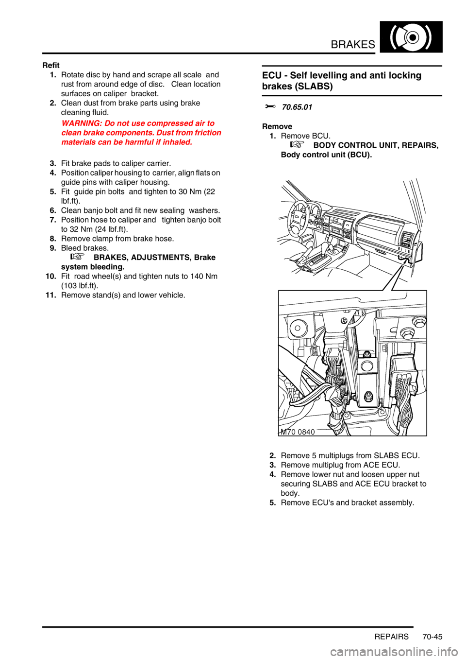
2.Remove 5 multiplugs from SLABS ECU.
3.Remove multiplug from ACE ECU.
4.Remove lower nut and loosen upper nut
securing SLABS and ACE ECU bracket to
body.
5.Remove ECU's and bracket assembly.
Page 1097 of 1672
RESTRAINT SYSTEMS
75-2 DESCRIPTION AND OPERATION
SRS block diagram
1DCU
2SRS warning lamp
3Driver airbag module
4Driver seat belt pretensioner
5Passenger airbag module
6Passenger seat belt pretensioner
Page 1106 of 1672

RESTRAINT SYSTEMS
DESCRIPTION AND OPERATION 75-11
DESCRIPTION AND OPERAT ION
Description - seat belts
An inertia reel, three point seat belt is installed at each seat position. The inertia reels incorporate a liftshaft locking
system with webbing sensor and car sensor activating mechanisms. The webbing sensor activates the locking system
if the webbing is subjected to a sharp pull. The car sensor activates the locking system if the vehicle is subjected to
sudden deceleration or a severe tilt angle.
Front seat belts
The inertia reel of each front seat belt is attached to the related B/C post, behind the finishers. The webbing runs from
the inertia reel, through a height adjuster, to an anchor point at the base of the B/C post. The buckle assembly for
each belt is attached to the inboard side of the seat and contains the SRS pretensioner.
Rear seat belts
The inertia reels for the outboard rear seats are attached to the body behind the loadspace side trim casings. The
webbing runs from each inertia reel through an upper mounting, suspended from the cantrail, to an anchor point on
the rear wheel arch.
The inertia reel of the centre rear seat is mounted in the back of the seat. The webbing runs through a guide on the
top of the seat and is anchored to one of the seat hinge points. The buckles for the rear seat belts are also attached
to the seat hinge points.
Third row seat belts
The inertia reel of each third row rear seat belt is attached to the related E post, behind the loadspace side trim
casing.The webbing runs from the inertia reel, through an upper mounting on the E post to an anchor point on the
loadspace floor. The buckle is mounted on the inboard side of the seat.
Page 1113 of 1672
RESTRAINT SYSTEMS
75-18 REPAIRS
Pre-tensioner - front seat belt
$% 76.73.30
WARNING: It is imperative that before any work
is undertaken on the SRS system the appropriate
information is read thoroughly.
WARNING: Always disconnect both battery leads
before beginning work on the SRS system.
Disconnect the negative battery lead first. Never
reverse connect the battery.
Remove
1.Remove the key from the starter switch.
Disconnect both battery leads, negative lead
first. Wait ten minutes before starting work.
2.Remove front seat.
+ SEATS, REPAIRS, Seat - front.
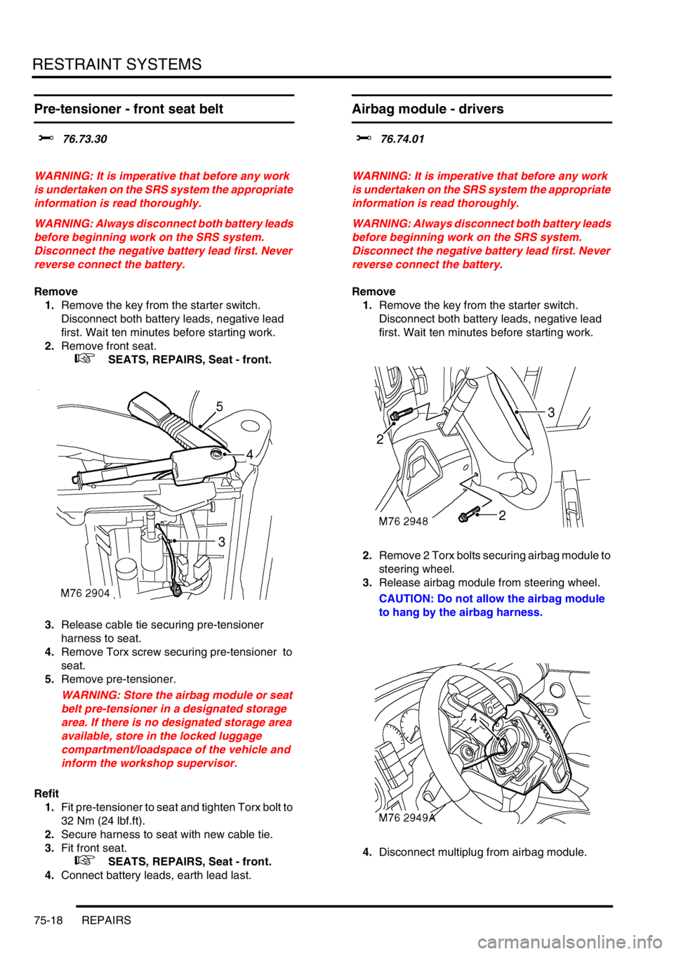
3.Release cable tie securing pre-tensioner
harness to seat.
4.Remove Torx screw securing pre-tensioner to
seat.
5.Remove pre-tensioner.
WARNING: Store the airbag module or seat
belt pre-tensioner in a designated storage
area. If there is no designated storage area
available, store in the locked luggage
compartment/loadspace of the vehicle and
inform the workshop supervisor.
Refit
1.Fit pre-tensioner to seat and tighten Torx bolt to
32 Nm (24 lbf.ft).
2.Secure harness to seat with new cable tie.
3.Fit front seat.
+ SEATS, REPAIRS, Seat - front.
4.Connect battery leads, earth lead last.
Airbag module - drivers
$% 76.74.01
WARNING: It is imperative that before any work
is undertaken on the SRS system the appropriate
information is read thoroughly.
WARNING: Always disconnect both battery leads
before beginning work on the SRS system.
Disconnect the negative battery lead first. Never
reverse connect the battery.
Remove
1.Remove the key from the starter switch.
Disconnect both battery leads, negative lead
first. Wait ten minutes before starting work.
2.Remove 2 Torx bolts securing airbag module to
steering wheel.
3.Release airbag module from steering wheel.
CAUTION: Do not allow the airbag module
to hang by the airbag harness.
4.Disconnect multiplug from airbag module.
Page 1114 of 1672
RESTRAINT SYSTEMS
REPAIRS 75-19
5.Remove airbag module.
WARNING: Store the airbag module with the
deployment side uppermost. If it is stored
deployment side down, accidental
deployment will propel the airbag module
with enough force to cause serious injury.
WARNING: Store the airbag module or seat
belt pre-tensioner in a designated storage
area. If there is no designated storage area
available, store in the locked luggage
compartment/loadspace of the vehicle and
inform the workshop supervisor.
Refit
NOTE: If the airbag module is to be replaced,
the bar code of the new module must be
recorded.
1.Position airbag module and connect multiplug.
2.Fit airbag module to steering wheel and tighten
Torx bolts to 9 Nm (7 lbf.ft).
3.Connect battery leads, earth lead last.
Airbag module - passenger
$% 76.74.02
WARNING: It is imperative that before any work
is undertaken on the SRS system the appropriate
information is read thoroughly.
WARNING: Always disconnect both battery leads
before beginning work on the SRS system.
Disconnect the negative battery lead first. Never
reverse connect the battery.
Remove
1.Remove the key from the starter switch.
Disconnect both battery leads, negative lead
first. Wait ten minutes before starting work.
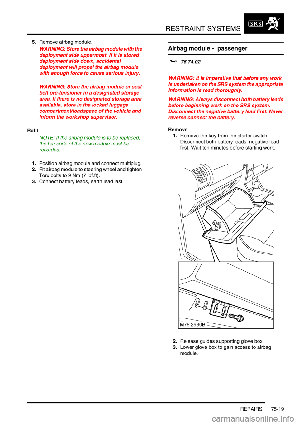
2.Release guides supporting glove box.
3.Lower glove box to gain access to airbag
module.
Page 1124 of 1672
DOORS
REPAIRS 76-1-1
DOORS REPAIRS
Door - front
$% 76.28.01.99
Remove
1.Release 'A' post lower trim and position aside.
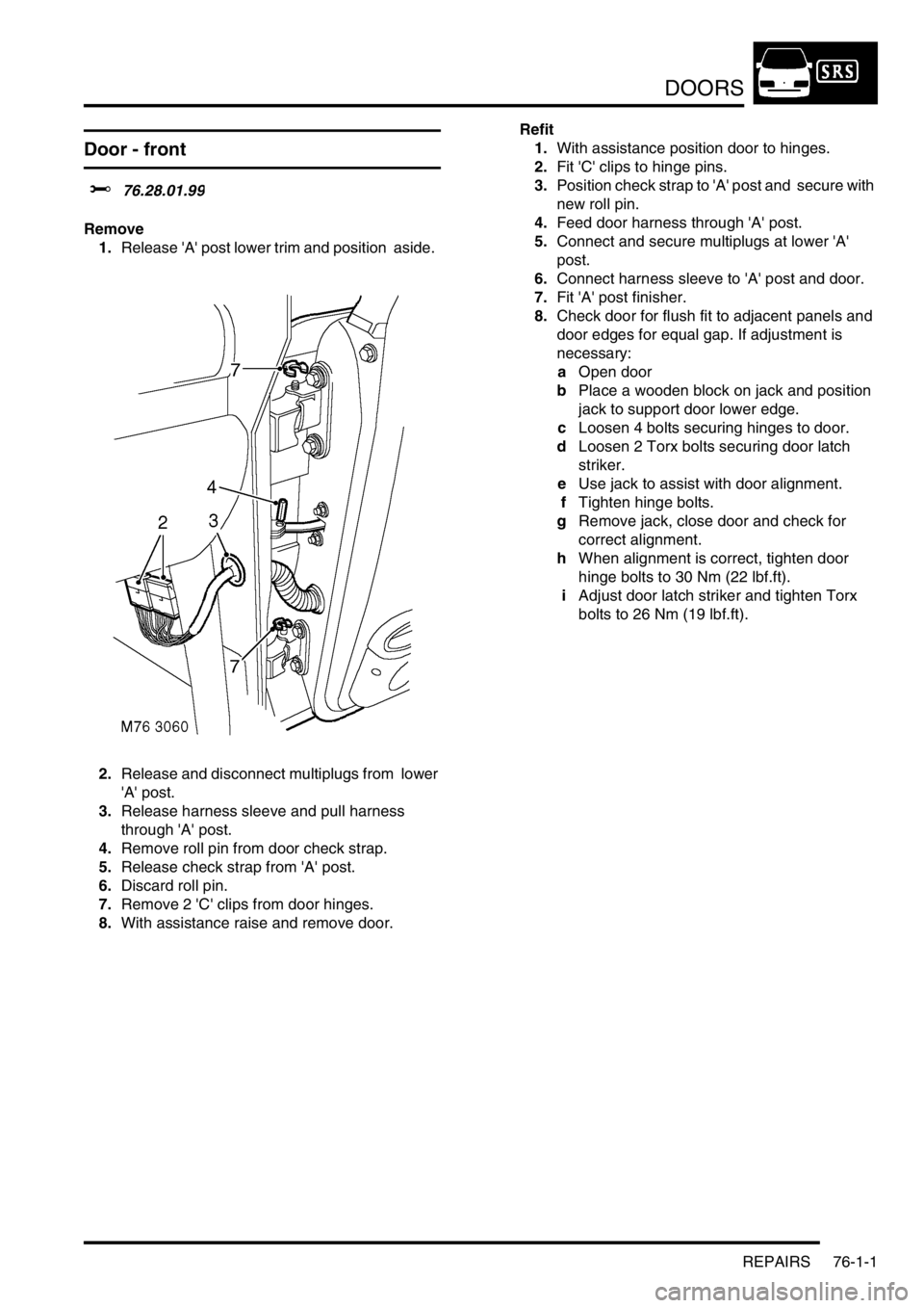
2.Release and disconnect multiplugs from lower
'A' post.
3.Release harness sleeve and pull harness
through 'A' post.
4.Remove roll pin from door check strap.
5.Release check strap from 'A' post.
6.Discard roll pin.
7.Remove 2 'C' clips from door hinges.
8.With assistance raise and remove door. Refit
1.With assistance position door to hinges.
2.Fit 'C' clips to hinge pins.
3.Position check strap to 'A' post and secure with
new roll pin.
4.Feed door harness through 'A' post.
5.Connect and secure multiplugs at lower 'A'
post.
6.Connect harness sleeve to 'A' post and door.
7.Fit 'A' post finisher.
8.Check door for flush fit to adjacent panels and
door edges for equal gap. If adjustment is
necessary:
aOpen door
bPlace a wooden block on jack and position
jack to support door lower edge.
cLoosen 4 bolts securing hinges to door.
dLoosen 2 Torx bolts securing door latch
striker.
eUse jack to assist with door alignment.
fTighten hinge bolts.
gRemove jack, close door and check for
correct alignment.
hWhen alignment is correct, tighten door
hinge bolts to 30 Nm (22 lbf.ft).
iAdjust door latch striker and tighten Torx
bolts to 26 Nm (19 lbf.ft).
Page 1125 of 1672
DOORS
76-1-2 REPAIRS
Door - rear
$% 76.28.02.99
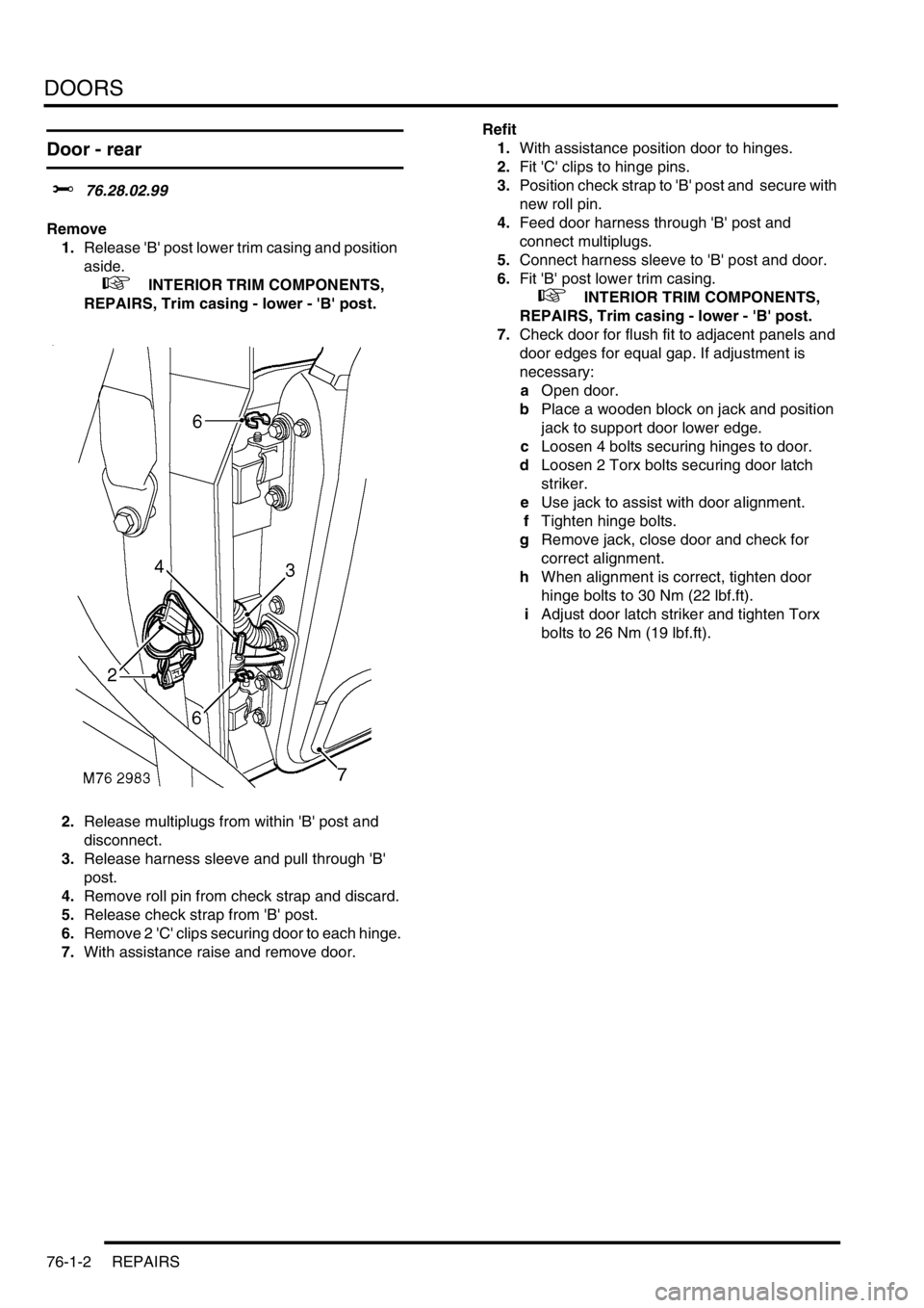
Remove
1.Release 'B' post lower trim casing and position
aside.
+ INTERIOR TRIM COMPONENTS,
REPAIRS, Trim casing - lower - 'B' post.
2.Release multiplugs from within 'B' post and
disconnect.
3.Release harness sleeve and pull through 'B'
post.
4.Remove roll pin from check strap and discard.
5.Release check strap from 'B' post.
6.Remove 2 'C' clips securing door to each hinge.
7.With assistance raise and remove door. Refit
1.With assistance position door to hinges.
2.Fit 'C' clips to hinge pins.
3.Position check strap to 'B' post and secure with
new roll pin.
4.Feed door harness through 'B' post and
connect multiplugs.
5.Connect harness sleeve to 'B' post and door.
6.Fit 'B' post lower trim casing.
+ INTERIOR TRIM COMPONENTS,
REPAIRS, Trim casing - lower - 'B' post.
7.Check door for flush fit to adjacent panels and
door edges for equal gap. If adjustment is
necessary:
aOpen door.
bPlace a wooden block on jack and position
jack to support door lower edge.
cLoosen 4 bolts securing hinges to door.
dLoosen 2 Torx bolts securing door latch
striker.
eUse jack to assist with door alignment.
fTighten hinge bolts.
gRemove jack, close door and check for
correct alignment.
hWhen alignment is correct, tighten door
hinge bolts to 30 Nm (22 lbf.ft).
iAdjust door latch striker and tighten Torx
bolts to 26 Nm (19 lbf.ft).
Page 1126 of 1672
DOORS
REPAIRS 76-1-3
Door - tail
$% 76.28.19.99
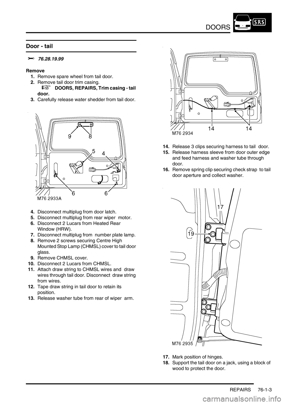
Remove
1.Remove spare wheel from tail door.
2.Remove tail door trim casing.
+ DOORS, REPAIRS, Trim casing - tail
door.
3.Carefully release water shedder from tail door.
4.Disconnect multiplug from door latch.
5.Disconnect multiplug from rear wiper motor.
6.Disconnect 2 Lucars from Heated Rear
Window (HRW).
7.Disconnect multiplug from number plate lamp.
8.Remove 2 screws securing Centre High
Mounted Stop Lamp (CHMSL) cover to tail door
glass.
9.Remove CHMSL cover.
10.Disconnect 2 Lucars from CHMSL.
11.Attach draw string to CHMSL wires and draw
wires through tail door. Disconnect draw string
from wires.
12.Tape draw string in tail door to retain its
position.
13.Release washer tube from rear of wiper arm. 14.Release 3 clips securing harness to tail door.
15.Release harness sleeve from door outer edge
and feed harness and washer tube through
door.
16.Remove spring clip securing check strap to tail
door aperture and collect washer.
17.Mark position of hinges.
18.Support the tail door on a jack, using a block of
wood to protect the door.