2002 LAND ROVER DISCOVERY Fuel system
[x] Cancel search: Fuel systemPage 1289 of 1672
PANEL REPAIRS
77-2-40 REPAIRS
13.Fit front door striker to B/C post, fit Torx bolts
and tighten to 26 Nm (19 lbf.ft).
14.Fit rear door.
+ DOORS, REPAIRS, Door - rear.
15.Connect leads/multiplug to alternator.
16.Connect battery leads, negative lead last.
Panel body side assembly
Remove
1.Disconnect both battery leads, negative lead
first.
2.Disconnect leads/multiplug from alternator.
3.Remove loadspace side trim casing.
+ INTERIOR TRIM COMPONENTS,
REPAIRS, Trim casing - side - loadspace.
4.Remove head lining rear trim finisher.
5.Remove rear head rests, if fitted.
6.Remove body side rear glass.
+ SCREENS, REPAIRS, Glass - body
side - rear.
7.Remove rear bumper assembly.
+ EXTERIOR FITTINGS, REPAIRS,
Bumper assembly - rear - up to 03MY.
8.Remove rear bumper finisher.
9.Remove rear wheel arch liner.
+ EXTERIOR FITTINGS, REPAIRS,
Liner - wheel arch - rear.
10.Remove mud flap.
11.Remove tread plate from rear door aperture.
12.Remove rear door aperture seal.
13.Remove rear door striker from 'D' post.
14.Remove 'D' post outer trim finisher.
15.Remove wheel arch trim finisher.
16.Remove side drip rail finisher.
17. RH side: Remove tail door.
18. LH side: Remove tail door striker and setting
block from 'E' post.
19.Remove tail door tread plate.
20.Remove loadspace carpet retainer.
21.Remove tail door aperture seal.
22.Remove tail lamp.
+ LIGHTING, REPAIRS, Lamp - tail.
23. RH side: Remove fuel filler flap.
24. RH side: Remove fuel filler tube.
+ FUEL DELIVERY SYSTEM - V8,
REPAIRS, Filler tube - fuel.
25.Remove aerial amplifier.
26.Remove relevant wiring from body side area.
Page 1290 of 1672
PANEL REPAIRS
REPAIRS 77-2-41
Repair
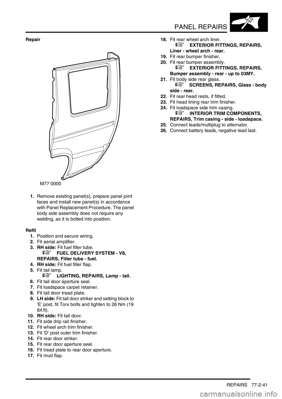
1.Remove existing panel(s), prepare panel joint
faces and install new panel(s) in accordance
with Panel Replacement Procedure. The panel
body side assembly does not require any
welding, as it is bolted into position.
Refit
1.Position and secure wiring.
2.Fit aerial amplifier.
3. RH side: Fit fuel filler tube.
+ FUEL DELIVERY SYSTEM - V8,
REPAIRS, Filler tube - fuel.
4. RH side: Fit fuel filler flap.
5.Fit tail lamp.
+ LIGHTING, REPAIRS, Lamp - tail.
6.Fit tail door aperture seal.
7.Fit loadspace carpet retainer.
8.Fit tail door tread plate.
9. LH side: Fit tail door striker and setting block to
'E' post, fit Torx bolts and tighten to 26 Nm (19
lbf.ft).
10. RH side: Fit tail door.
11.Fit side drip rail finisher.
12.Fit wheel arch trim finisher.
13.Fit 'D' post outer trim finisher.
14.Fit rear door striker.
15.Fit rear door aperture seal.
16.Fit tread plate to rear door aperture.
17.Fit mud flap.18.Fit rear wheel arch liner.
+ EXTERIOR FITTINGS, REPAIRS,
Liner - wheel arch - rear.
19.Fit rear bumper finisher.
20.Fit rear bumper assembly.
+ EXTERIOR FITTINGS, REPAIRS,
Bumper assembly - rear - up to 03MY.
21.Fit body side rear glass.
+ SCREENS, REPAIRS, Glass - body
side - rear.
22.Fit rear head rests, if fitted.
23.Fit head lining rear trim finisher.
24.Fit loadspace side trim casing.
+ INTERIOR TRIM COMPONENTS,
REPAIRS, Trim casing - side - loadspace.
25.Connect leads/multiplug to alternator.
26.Connect battery leads, negative lead last.
M77 0000
Page 1291 of 1672
PANEL REPAIRS
77-2-42 REPAIRS
Body side inner rear assembly
In this procedure, the panel body side assembly is
replaced in conjunction with the body side inner rear
assembly.
Remove
1.Disconnect battery eath lead.
2.Disconnect leads/multiplug from alternator.
3.Remove panel body side assembly.
+ PANEL REPAIRS, REPAIRS, Panel
body side assembly.
4.Remove RH or LH rear seat.
+ SEATS, REPAIRS, Seat - rear.
5.Remove loadspace carpet.
+ INTERIOR TRIM COMPONENTS,
REPAIRS, Carpet - loadspace.
6.Remove rear side seat belt.
+ RESTRAINT SYSTEMS, REPAIRS,
Seat belt - rear - side.
7.Remove third row seat belt.
+ RESTRAINT SYSTEMS, REPAIRS,
Seat belts - third row.
8.Remove fuel tank.
+ FUEL DELIVERY SYSTEM - V8,
REPAIRS, Tank - fuel.
+ FUEL DELIVERY SYSTEM - Td5,
REPAIRS, Tank - fuel.
9.Remove fuel filler tube.
+ FUEL DELIVERY SYSTEM - V8,
REPAIRS, Filler tube - fuel.
10. RH side: Remove fuel flap release solenoid.
+ FUEL DELIVERY SYSTEM - Td5,
REPAIRS, Solenoid - fuel filler flap release.
+ FUEL DELIVERY SYSTEM - V8,
REPAIRS, Solenoid - fuel filler flap release.
11. RH side: Remove air extractor vent.
12.Remove relevant wiring.Repair
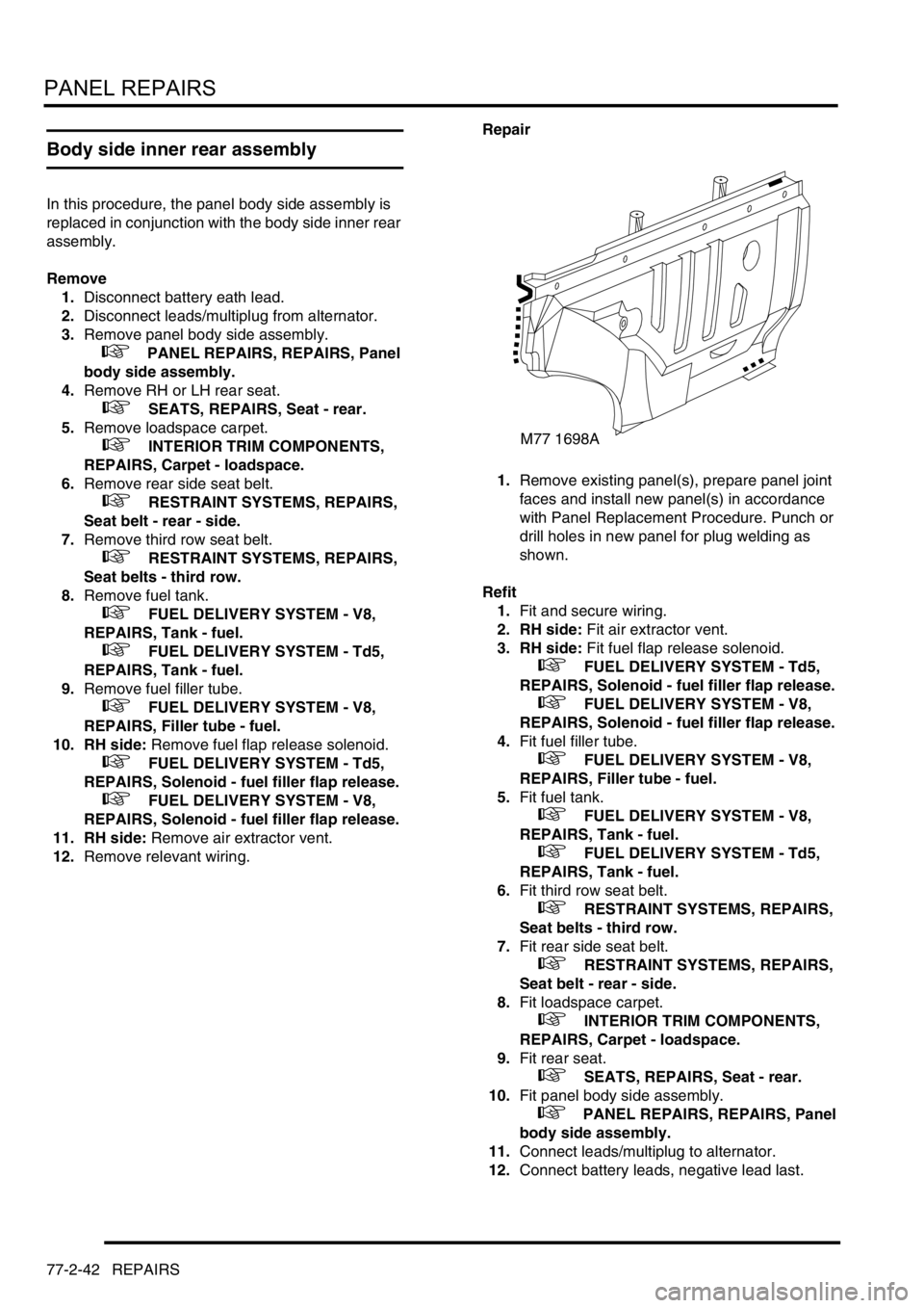
1.Remove existing panel(s), prepare panel joint
faces and install new panel(s) in accordance
with Panel Replacement Procedure. Punch or
drill holes in new panel for plug welding as
shown.
Refit
1.Fit and secure wiring.
2. RH side: Fit air extractor vent.
3. RH side: Fit fuel flap release solenoid.
+ FUEL DELIVERY SYSTEM - Td5,
REPAIRS, Solenoid - fuel filler flap release.
+ FUEL DELIVERY SYSTEM - V8,
REPAIRS, Solenoid - fuel filler flap release.
4.Fit fuel filler tube.
+ FUEL DELIVERY SYSTEM - V8,
REPAIRS, Filler tube - fuel.
5.Fit fuel tank.
+ FUEL DELIVERY SYSTEM - V8,
REPAIRS, Tank - fuel.
+ FUEL DELIVERY SYSTEM - Td5,
REPAIRS, Tank - fuel.
6.Fit third row seat belt.
+ RESTRAINT SYSTEMS, REPAIRS,
Seat belts - third row.
7.Fit rear side seat belt.
+ RESTRAINT SYSTEMS, REPAIRS,
Seat belt - rear - side.
8.Fit loadspace carpet.
+ INTERIOR TRIM COMPONENTS,
REPAIRS, Carpet - loadspace.
9.Fit rear seat.
+ SEATS, REPAIRS, Seat - rear.
10.Fit panel body side assembly.
+ PANEL REPAIRS, REPAIRS, Panel
body side assembly.
11.Connect leads/multiplug to alternator.
12.Connect battery leads, negative lead last.
M77 1698A
Page 1297 of 1672
PANEL REPAIRS
77-2-48 REPAIRS
Cross member outer rear panel (RH/LH
section)
In this procedure, the panel body side assembly and
the 'E' post assembly are replaced in conjunction
with either the RH or LH section of the cross member
outer rear panel.
Remove
1.Disconnect both battery leads, negative lead
first.
2.Disconnect leads/multiplug from alternator.
3.Remove 'E' post assembly.
+ PANEL REPAIRS, REPAIRS, 'E' post
assembly.
4.Remove rear folding step.
+ EXTERIOR FITTINGS, REPAIRS,
Rear folding step.
5. LH side: Remove exhaust tailpipe heatshield.
6.Remove relevant wiring.
Repair
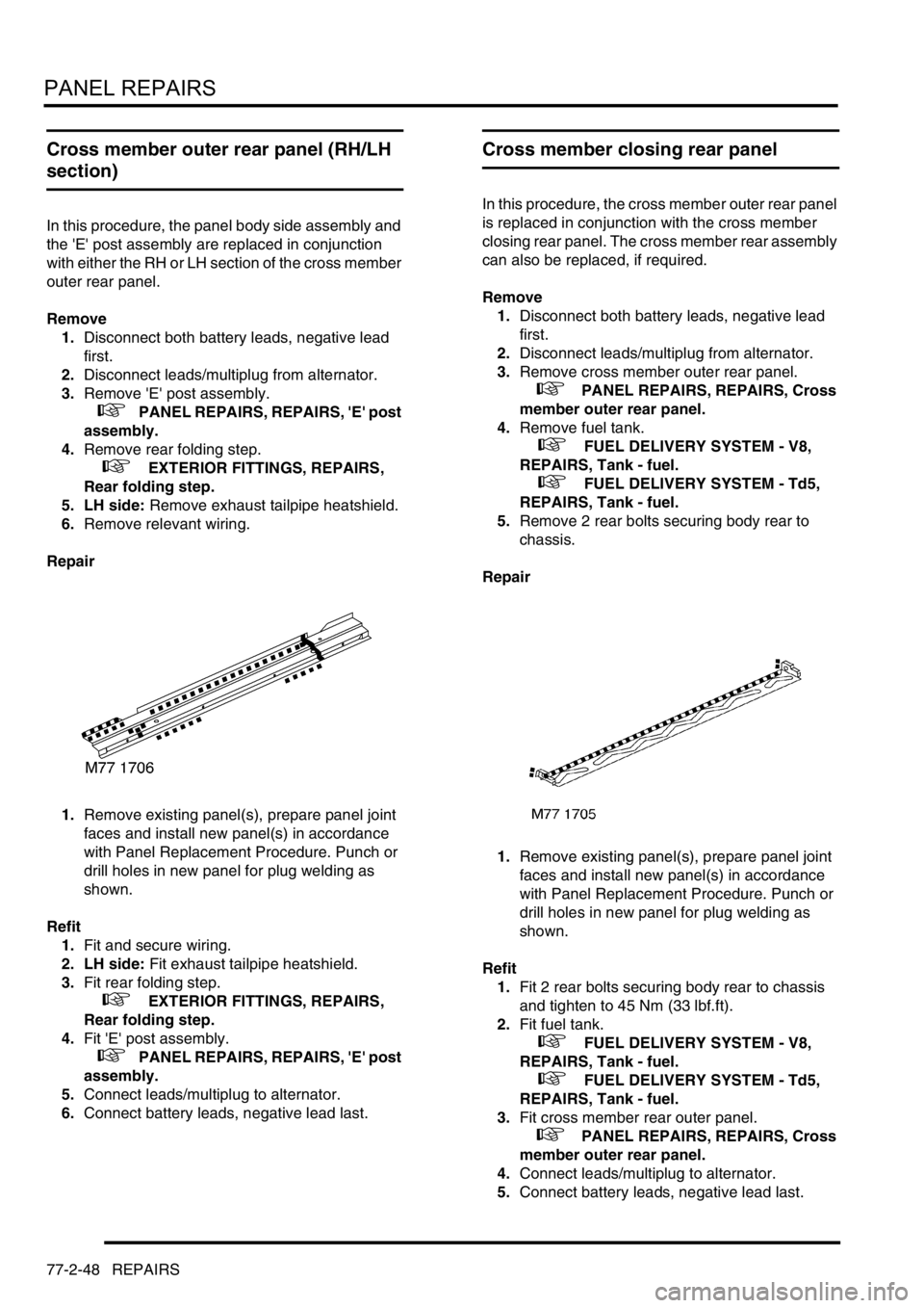
1.Remove existing panel(s), prepare panel joint
faces and install new panel(s) in accordance
with Panel Replacement Procedure. Punch or
drill holes in new panel for plug welding as
shown.
Refit
1.Fit and secure wiring.
2. LH side: Fit exhaust tailpipe heatshield.
3.Fit rear folding step.
+ EXTERIOR FITTINGS, REPAIRS,
Rear folding step.
4.Fit 'E' post assembly.
+ PANEL REPAIRS, REPAIRS, 'E' post
assembly.
5.Connect leads/multiplug to alternator.
6.Connect battery leads, negative lead last.
Cross member closing rear panel
In this procedure, the cross member outer rear panel
is replaced in conjunction with the cross member
closing rear panel. The cross member rear assembly
can also be replaced, if required.
Remove
1.Disconnect both battery leads, negative lead
first.
2.Disconnect leads/multiplug from alternator.
3.Remove cross member outer rear panel.
+ PANEL REPAIRS, REPAIRS, Cross
member outer rear panel.
4.Remove fuel tank.
+ FUEL DELIVERY SYSTEM - V8,
REPAIRS, Tank - fuel.
+ FUEL DELIVERY SYSTEM - Td5,
REPAIRS, Tank - fuel.
5.Remove 2 rear bolts securing body rear to
chassis.
Repair
1.Remove existing panel(s), prepare panel joint
faces and install new panel(s) in accordance
with Panel Replacement Procedure. Punch or
drill holes in new panel for plug welding as
shown.
Refit
1.Fit 2 rear bolts securing body rear to chassis
and tighten to 45 Nm (33 lbf.ft).
2.Fit fuel tank.
+ FUEL DELIVERY SYSTEM - V8,
REPAIRS, Tank - fuel.
+ FUEL DELIVERY SYSTEM - Td5,
REPAIRS, Tank - fuel.
3.Fit cross member rear outer panel.
+ PANEL REPAIRS, REPAIRS, Cross
member outer rear panel.
4.Connect leads/multiplug to alternator.
5.Connect battery leads, negative lead last.
Page 1344 of 1672
HEATING AND VENTILATION
DESCRIPTION AND OPERATION 80-3
Description
General
The heating and ventilation system controls the temperature and distribution of air supplied to the vehicle interior. The
system consists of an air inlet duct, heater assembly, distribution ducts and a control panel. An outlet vent is
incorporated at the rear of the cabin. Some diesel models also incorporate a fuel burning heater (FBH) system in the
engine coolant supply to the heater assembly.
Fresh or recirculated air flows into the heater assembly from the inlet duct. An electrical variable speed blower in the
inlet duct, and/or ram effect, forces the air through the system. Depending on the settings on the control panel, the air
is then heated and supplied through the distribution ducts to fascia and floor level outlets.
Page 1349 of 1672
HEATING AND VENTILATION
80-8DESCRIPTION AND OPERATION
Control panel
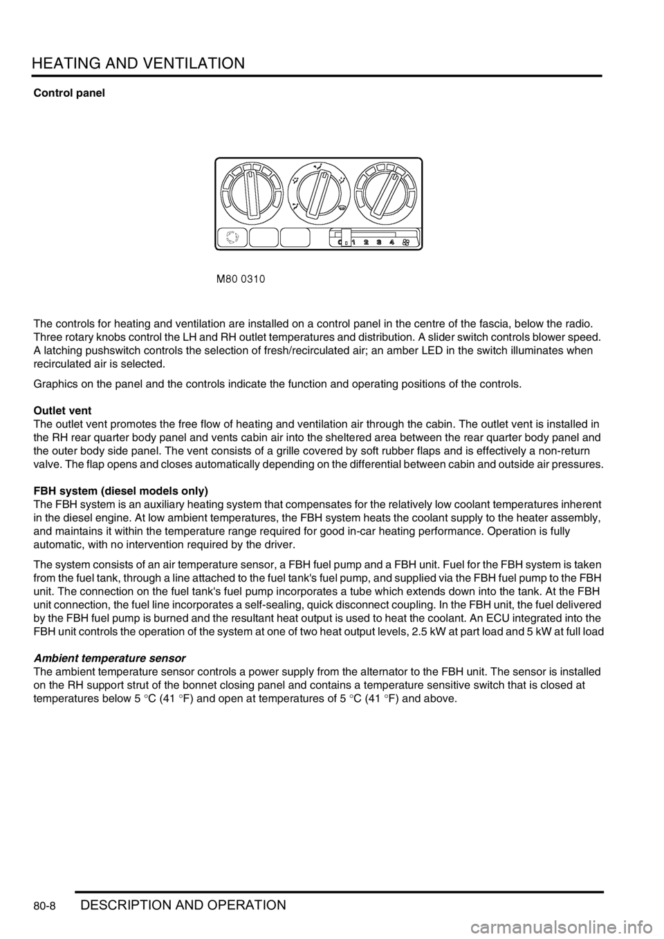
The controls for heating and ventilation are installed on a control panel in the centre of the fascia, below the radio.
Three rotary knobs control the LH and RH outlet temperatures and distribution. A slider switch controls blower speed.
A latching pushswitch controls the selection of fresh/recirculated air; an amber LED in the switch illuminates when
recirculated air is selected.
Graphics on the panel and the controls indicate the function and operating positions of the controls.
Outlet vent
The outlet vent promotes the free flow of heating and ventilation air through the cabin. The outlet vent is installed in
the RH rear quarter body panel and vents cabin air into the sheltered area between the rear quarter body panel and
the outer body side panel. The vent consists of a grille covered by soft rubber flaps and is effectively a non-return
valve. The flap opens and closes automatically depending on the differential between cabin and outside air pressures.
FBH system (diesel models only)
The FBH system is an auxiliary heating system that compensates for the relatively low coolant temperatures inherent
in the diesel engine. At low ambient temperatures, the FBH system heats the coolant supply to the heater assembly,
and maintains it within the temperature range required for good in-car heating performance. Operation is fully
automatic, with no intervention required by the driver.
The system consists of an air temperature sensor, a FBH fuel pump and a FBH unit. Fuel for the FBH system is taken
from the fuel tank, through a line attached to the fuel tank's fuel pump, and supplied via the FBH fuel pump to the FBH
unit. The connection on the fuel tank's fuel pump incorporates a tube which extends down into the tank. At the FBH
unit connection, the fuel line incorporates a self-sealing, quick disconnect coupling. In the FBH unit, the fuel delivered
by the FBH fuel pump is burned and the resultant heat output is used to heat the coolant. An ECU integrated into the
FBH unit controls the operation of the system at one of two heat output levels, 2.5 kW at part load and 5 kW at full load
Ambient temperature sensor
The ambient temperature sensor controls a power supply from the alternator to the FBH unit. The sensor is installed
on the RH support strut of the bonnet closing panel and contains a temperature sensitive switch that is closed at
temperatures below 5
°C (41 °F) and open at temperatures of 5 °C (41 °F) and above.
Page 1353 of 1672

HEATING AND VENTILATION
80-12DESCRIPTION AND OPERATION
Circulation pump. The circulation pump is installed at the coolant inlet to the FBH unit to assist the coolant flow through
the FBH unit and the heater assembly. The pump runs continuously while the FBH unit is in standby or active
operating modes. While the FBH unit is inactive, coolant flow is reliant on the engine coolant pump.
Combustion air fan. The combustion air fan regulates the flow of air into the unit to support combustion of the fuel
supplied by the FBH pump. It also supplies the air required to purge and cool the FBH unit. Ambient air is supplied to
the combustion air fan through an air inlet hose containing a sound deadening foam ring.
Burner housing. The burner housing contains the burner insert and also incorporates connections for the exhaust
pipe, the coolant inlet from the circulation pump and the coolant outlet to the heater assembly. The exhaust pipe
directs exhaust combustion gases to atmosphere at the bottom of the engine compartment.
The burner insert incorporates the fuel combustion chamber, an evaporator and a glow plug/flame sensor. Fuel from
the FBH fuel pump is supplied to the evaporator, where it evaporates and enters the combustion chamber to mix with
air from the combustion air fan. The glow plug/flame sensor provides the ignition source of the fuel:air mixture and,
once combustion is established, monitors the flame.
ECU/heat exchanger. The ECU controls and monitors operation of the FBH system. Ventilation of the ECU is
provided by an internal flow of air from the combustion air fan. The heat exchanger transfers heat generated by
combustion to the coolant. A sensor in the heat exchanger provides the ECU with an input of heat exchanger casing
temperature, which the ECU relates to coolant temperature and uses to control system operation. The temperature
settings in the ECU are calibrated to compensate for the difference between coolant temperature and the heat
exchanger casing temperature detected by the sensor. Typically: as the coolant temperature increases, the coolant
will be approximately 7
°C (12.6 °F) hotter than the temperature detected by the sensor; as the coolant temperature
decreases, the coolant will be approximately 2
°C (3.6 °F) cooler than the temperature detected by the sensor.
Page 1354 of 1672
HEATING AND VENTILATION
DESCRIPTION AND OPERATION 80-13
Operation
Air distribution
Turning the distribution knob on the control panel turns the control flaps in the heater assembly to direct air to the
corresponding fascia and footwell outlets.
Air temperature
Turning the LH or RH temperature knob on the control panel turns the related blend flaps in the heater assembly. The
blend flaps vary the proportion of air going through the cold air bypass and the heater matrix. The proportion varies,
between full bypass no heat and no bypass full heat, to correspond with the position of the temperature knob.
Blower speed
The blower can be selected off or to run at one of four speeds. While the ignition is on, when the blower switch is set
to positions 1, 2, 3, or 4, ignition power energises the blower relay, which supplies battery power to the blower. At
switch positions 1, 2 and 3, the blower switch also connects the blower to different earth paths through the resistor
pack, to produce corresponding differences of blower operating voltage and speed. At position 4, the blower switch
connects an earth direct to the blower, bypassing the resistor pack, and full battery voltage drives the blower at
maximum speed.
Fresh/Recirculated inlet air
When the recirculated air switch is latched in, the amber indicator LED in the switch illuminates and an earth is
connected to the recirculated air side of the fresh/recirculated air servo motor. The fresh/recirculated air servo motor
then turns the control flaps in the air inlet duct to close the fresh air inlet and open the recirculated air inlets.
When the latch of the recirculated air switch is released, the amber indicator LED in the switch extinguishes and the
earth is switched from the recirculated air side to the fresh air side of the fresh/recirculated air servo motor. The fresh/
recirculated air servo motor then turns the control flaps in the air inlet duct to open the fresh air inlet and close the
recirculated air inlets.
FBH system (where fitted)
The FBH system operates only while the engine is running and the ambient temperature is less than 5
°C (41 °F).
With the engine running and the ambient temperature below 5
°C (41 °F), the air temperature sensor connects the
alternator power supply to the ECU in the FBH unit. On receipt of the alternator power supply, the ECU starts the
circulation pump and, depending on the input from the temperature sensor in the heat exchanger, enters either a
standby or active mode of operation. If the heat exchanger casing temperature is 65
°C (149 °F) or above, the ECU
enters a standby mode of operation. If the heat exchanger casing temperature is below 65
°C (149 °F), the ECU enters
an active mode of operation. In the standby mode, the ECU monitors the heat exchanger casing temperature and
enters the active mode if it drops below 65
°C (149 °F). In the active mode, the ECU initiates a start sequence and
then operates the system at full or part load combustion to provide the required heat input to the coolant.
Start sequence
At the beginning of the start sequence the ECU energises the glow plug function of the glow plug/flame sensor, to
preheat the combustion chamber, and starts the combustion air fan at slow speed. After 30 seconds, the ECU
energises the FBH fuel pump at the starting sequence speed. The fuel delivered by the FBH fuel pump evaporates in
the combustion chamber, mixes with air from the combustion air fan and is ignited by the glow plug/flame sensor. The
ECU then progressively increases the speed of the FBH fuel pump and the combustion air fan to either part or full
load speed, as required by the system. Once full or part load speed is achieved, the ECU switches the glow plug/flame
sensor from the glow plug function to the flame sensing function to monitor combustion. From the beginning of the
start sequence to stable combustion takes approximately 90 seconds for a start to part load combustion and 150
seconds for a start to full load combustion.