2002 LAND ROVER DISCOVERY Fuel system
[x] Cancel search: Fuel systemPage 1527 of 1672

ALARM SYSTEM AND HORN
86-4-18 DESCRIPTION AND OPERATION
Perimetric alarm
The perimetric alarm is used by the BCU to detect unauthorised opening of a door or hinged panel. Switches
incorporated into the door latch assemblies and the bonnet determine the state of the panels.
There are two perimetric alarm configurations:
lAlarm not active.
lAlarm active.
Arming: To arm the perimetric alarm, press the lock button on the handset or lock the vehicle using the key in the
driver's door. Once the alarm has been set, the BCU monitors the state of the doors and the bonnet.
In order to arm the perimetric alarm the following conditions must be met:
lDrivers door closed.
lKey not inserted in ignition switch.
lFuel cut-off switch not tripped.
Disarming: To prevent the alarm from triggering when entering the vehicle, the alarm system must be disarmed with
the key or the handset.
There are two perimetric alarm disarming configurations:
lAlways disarm with key.
lOnly disarm with key if locked with key.
The perimetric alarm can be disarmed by unlocking the vehicle with the handset or by using the key in the driver's
door lock, depending on system configuration.
NOTE: The “only disarm with key if locked with key” configuration prevents the alarm from being disarmed by
unlocking the vehicle with the handset if the vehicle has been locked by the key. In this situation the Emergency Key
Access (EKA) code must be entered to disarm the alarm.
In order for the alarm to trigger, the following conditions must be met:
lPerimetric alarm armed.
lBonnet or door opened.
Once triggered, the alarm will remain triggered for 30 seconds before resetting.
Volumetric alarm
The volumetric alarm is used by the BCU to detect movement within the vehicle. This allows the alarm to be triggered
if a window is smashed in an attempt to gain access to the vehicle.
There are two volumetric alarm configurations:
lVolumetric alarm not active.
lVolumetric alarm active.
Two sensors, which transmit and receive ultrasonic signals, detect movement within the vehicle. Theses sensors
detect any change in air movement within the vehicle and then supply the BCU a signal to activate the alarm. Fifteen
seconds after the vehicle is locked with the handset or the key the volumetric alarm is armed. This delay is
incorporated into the BCU software to prevent accidental or nuisance triggering of the alarm.
In order to arm the volumetric alarm, the following conditions must be met:
lDriver's door closed.
lKey not inserted in ignition.
lFuel cut-off switch not tripped.
To prevent the alarm from triggering when entering the vehicle, the alarm system must be disarmed with the key or
the handset.
There are two volumetric alarm disarming configurations:
lAlways disarm with key.
lOnly disarm with key if locked with key.
Page 1528 of 1672

ALARM SYSTEM AND HORN
DESCRIPTION AND OPERATION 86-4-19
The volumetric alarm can be disarmed by unlocking the driver's door with the key or the handset, depending on
system configuration.
NOTE: The “only disarm with key if locked with key” configuration prevents the alarm from being disarmed by
unlocking the vehicle with the handset if the vehicle has been locked by the key. In this situation the EKA code must
be entered to disarm the alarm.
In order for the alarm to trigger, the following conditions must be met:
lVolumetric alarm armed.
lVolumetric sensors triggered.
Once triggered, the alarm will remain triggered for 30 seconds before resetting.
Super locking
Super locking prevents the use of the interior door handles to unlock and open the vehicle doors. This prevents the
doors from being opened if the window be smashed in an attempt to gain access to the vehicle.
There are four configurations for super locking:
lNo super locking.
lSuper locking on single handset press only (no key activated super locking).
lSuper locking on single handset press or single key turn.
lSuper locking on double handset press or double key turn.
To super lock, press the lock button on the handset once or twice within one second depending on system
configuration. In some configurations, it is also possible to super lock the vehicle using the key in the driver's door.
This also may require one or two turns of the key in the lock direction. If two turns of the key are required to activate
super locking, the two turns must occur within one second of each other.
In order to super lock the vehicle, the following conditions must be met:
lAll door are closed.
lThe ignition is off.
lThe fuel cut-off switch is not tripped.
Partial arming
Partial arming allows protection of as much of the vehicle as possible if the alarm is armed with one or more doors or
the bonnet open.
Partial arming allows the vehicle alarm to be armed even if the following conditions exist. When the bonnet or door is
closed, the BCU activates the perimetric alarm and the volumetric alarm after 15 seconds have elapsed:
lThe bonnet is not closed: If the bonnet is open when the alarm is armed, the BCU activates super locking and
volumetric sensing. In this condition, the alarm enters a partially armed state. All other functions of the alarm are
active and the BCU monitors the bonnet for a change of state. If the bonnet closes, the system is completely
armed.
lThe passenger door, a rear door or the tail door is not closed: If a door is open when the alarm is armed, the BCU
does not activate super locking or volumetric sensing. In this condition the alarm enters a partially armed state.
All other alarm functions are armed and the BCU monitors the open door. If the door closes volumetric sensing
and super locking become active.
lFailure of a door latch switch: If a short circuit in the door latch switch occurs, the BCU presumes the door is not
closed. In this situation the BCU does not activate super locking or volumetric sensing. All other alarm functions
are armed.
lDamaged wiring harness: If a short circuit in the wiring harness for the door latch switch occurs, the BCU
presumes the door is not closed and does not activate super locking or volumetric sensing; all other alarm
functions are armed. If an open circuit in the wiring harness for the door latch switch occurs, the BCU presumes
the door is closed and arms the alarm as normal.
Page 1529 of 1672

ALARM SYSTEM AND HORN
86-4-20 DESCRIPTION AND OPERATION
Mislock
Mislock alerts the driver that a failed attempt has been made to lock the vehicle because of the doors or the bonnet
not being fully closed.
There are six audible configurations for mislock:
lNo audible warning.
lAlarm sounder.
lVehicle horn.
lAlarm sounder and vehicle horn.
lBBUS.
lAlarm sounder, vehicle horn and BBUS.
When a failed attempt has been made to lock the vehicle, the audible warning device is switched on for 50 ms and
off for 200 ms. The BCU allows the audible warning device to operate 3 times.
Passive immobilisation
Passive immobilisation prevents the vehicle from being started unless the authorised key is used to start the vehicle.
There are only two configurations for passive immobilisation:
lpassive immobilisation not active
lpassive immobilisation active
When the ignition is switched off, the vehicle remains mobilised for up to a maximum of 5 minutes. If however the
driver's door is opened, after 2 minutes 30 seconds, the vehicle remains in a mobilised state for a further 30 seconds.
When the timer in the BCU has expired, the vehicle is immobilised.
Once the ignition is switched on, the BCU transmits a coded signal to the ECM. If the coded signal does not
correspond to the programmed code in the ECM, the ECM is inhibited and the BCU inhibits the starting circuit.
In order for passive immobilisation to occur, the following conditions must be met:
lDriver's door closed.
lFuel cut-off switch not tripped.
lKey not inserted in ignition.
Passive remobilisation
Whenever the vehicle is immobilised, passive remobilisation of the engine occurs when the ignition is switched on,
allowing the vehicle to be started.
There are three configurations for passive remobilisation:
lPassive immobilisation not active.
lPassive immobilisation active.
lEKA with super locking on receiving good passive remobilisation exciter coil signal.
The BCU controls the passive remobilisation exciter coil (located around the ignition barrel) to generate a magnetic
field which causes the handset to transmit a remobilisation signal. The BCU receives the signal and allows the vehicle
to be started. If a valid signal from the handset is not received within one minute of the ignition being switched to
position II, the BCU stops the passive coil from generating the magnetic field.
Page 1579 of 1672

HARNESSES
86-7-8 REPAIRS
35.Secure harness to LH side of body with cable
tie clips and retainers.
36.Connect and secure multiplugs to lower LH 'A'
post.
37.Feed harness through roof to centre.
38.Secure harness behind bonnet release cable.
39.Connect rear washer pipe at lower 'A' post and
secure with clip.
40.Secure harness to roof with clips.
41.Connect multiplug to interior mirror, ARC
accelerometer.
42.Position sound deadening panels and secure
with clips.
43.Fit headlining.
+ INTERIOR TRIM COMPONENTS,
REPAIRS, Headlining.
44.Fit fascia panel.
+ INTERIOR TRIM COMPONENTS,
REPAIRS, Fascia.
Harness - engine - V8
$% 86.70.17
Remove
1.Remove upper inlet manifold.
+ MANIFOLDS AND EXHAUST
SYSTEMS - V8, REPAIRS, Gasket - inlet
manifold - upper - Without Secondary Air
Injection.
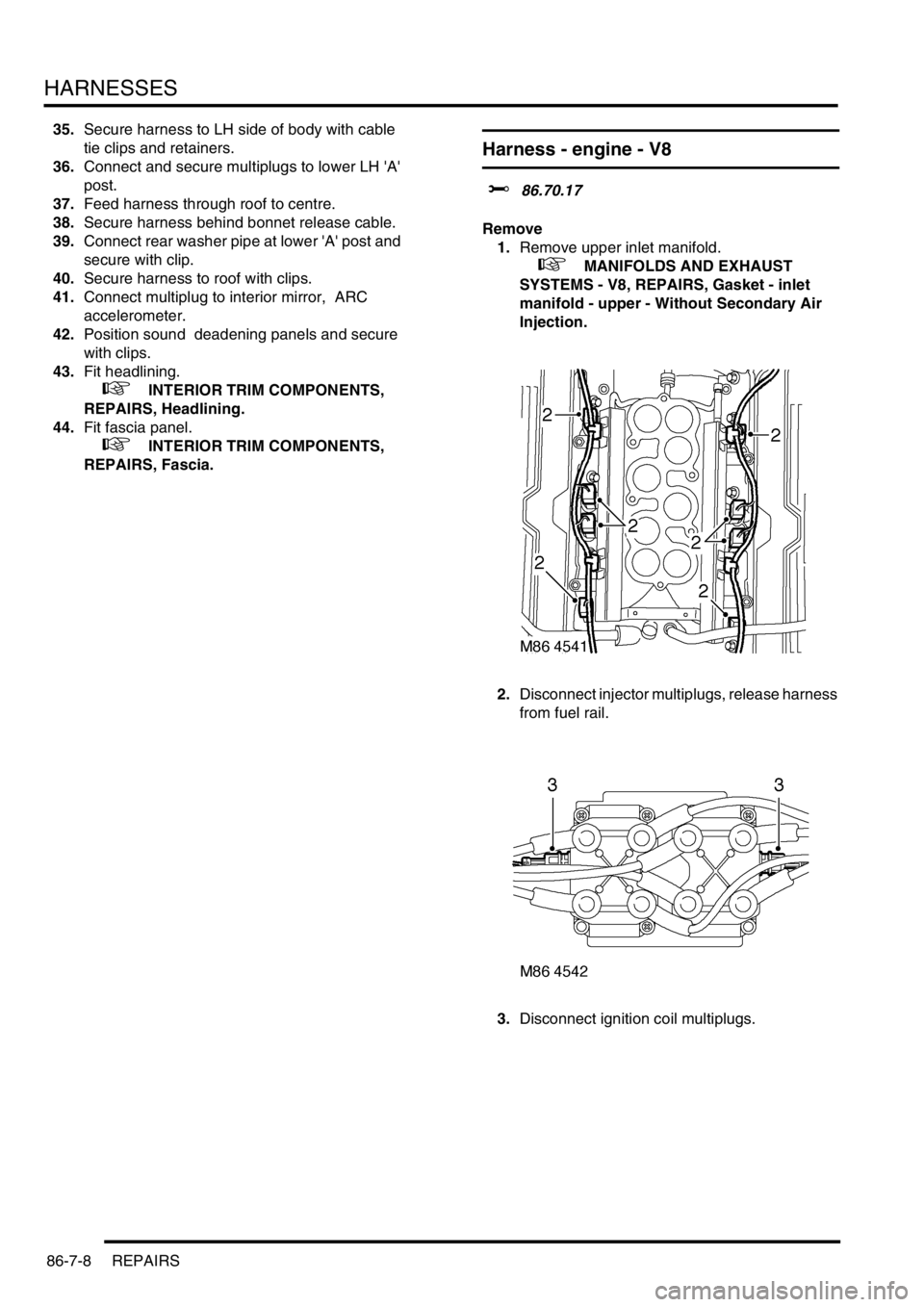
2.Disconnect injector multiplugs, release harness
from fuel rail.
3.Disconnect ignition coil multiplugs.
Page 1599 of 1672

HARNESSES
86-7-28 REPAIRS
18.Secure multiplugs to steering column support
bracket and connect brake and clutch pedal
multiplugs.
19.Connect multiplugs to column switch and
passive coil.
20.Position passenger compartment fusebox,
connect multiplugs, fit fusebox to fascia and
secure with nut.
21.Connect ignition switch multiplug to fuse box.
22.With assistance feed LH side of harness into
engine bay.
23.Connect multiplugs to front door harness and
body harness.
24.Position earth headers to LH lower 'A' post and
secure with nuts.
25.Connect multiplugs to ECU pack.
26.Position harness in engine bay.
27.Connect and secure heated front screen
multiplugs.
28.Fit plenum molding.
+ HEATING AND VENTILATION,
REPAIRS, Plenum Air Intake.
29.Connect multiplugs to ABS sensor and fuel
cut-off switch.
30.Using draw string feed harness through inner
wing, remove draw string, connect repeater
lamp multiplug and fit lamp.
31.Connect multiplugs to ABS modulator.
32.Feed harness through to front panel.
33.Position body earth leads and secure with
bolts.
34.Connect washer reservoir multiplugs and
pipes, secure pipes with clips.
35.Secure fog lamp multiplug.
36.Secure earth header behind headlamp.
37.Connect multiplugs to headlamp level motor,
headlamp and side lamp.
38.Fit indicator lamp
+ LIGHTING, REPAIRS, Lamp - front
repeater.
39.Connect multiplug to LH horn.
40.Feed harness to ACE accelerometer, connect
multiplug and secure with cable ties.
41.Connect cruise control, ABS sensor and brake
fluid level switch multiplugs.
42.Connect engine harness multiplug and feed
harness along RH wing to fuse box.
43.Using draw string pull harness through inner
wing, remove draw string, connect repeater
lamp multiplug and fit lamp. 44.Connect chassis harness multiplugs.
45.Position engine bay fuse box and connect
multiplugs, fit fuse box and secure with screws.
46.Connect multiplugs to front of fuse box.
47.Position battery and starter cables and secure
with screws.
48.Fit fuse box cover.
49.Position earth lead and secure with nut.
50.Feed harness through to front panel.
51.Secure fog lamp multiplug.
52.Connect headlamp level motor, headlamp and
side lamp multiplugs.
53.Fit indicator lamp.
+ LIGHTING, REPAIRS, Lamp - front
repeater.
54.Secure harness to RH front panel.
55.Connect cooling fan and horn multiplug.
56.Secure harness to lower support rail.
57.Connect receiver drier and air temperature
sensor multiplugs.
58.Fit front bumper.
+ EXTERIOR FITTINGS, REPAIRS,
Bumper assembly - front.
59.Fit battery tray.
60.Fit air filter assembly.
+ ENGINE MANAGEMENT SYSTEM -
V8, REPAIRS, Air cleaner assembly.
61.Position both lower 'A' post trims and secure
with studs.
62.Fit heater assembly.
+ HEATING AND VENTILATION,
REPAIRS, Heater assembly - models with
air conditioning.
+ HEATING AND VENTILATION,
REPAIRS, Heater assembly - models
without air conditioning.
Page 1607 of 1672

DRIVING AIDS
86-8-8 DESCRIPTION AND OPERATION
PDC Switch
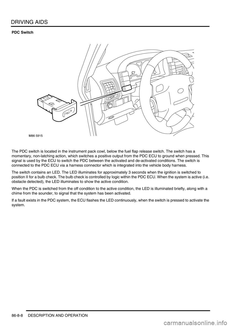
The PDC switch is located in the instrument pack cowl, below the fuel flap release switch. The switch has a
momentary, non-latching action, which switches a positive output from the PDC ECU to ground when pressed. This
signal is used by the ECU to switch the PDC between the activated and de-activated conditions. The switch is
connected to the PDC ECU via a harness connector which is integrated into the vehicle body harness.
The switch contains an LED. The LED illuminates for approximately 3 seconds when the ignition is switched to
position II for a bulb check. The bulb check is controlled by logic within the PDC ECU. When the system is active (i.e.
obstacle detected), the LED illuminates to show the active condition.
When the PDC is switched from the off condition to the active condition, the LED is illuminated briefly, along with a
chime from the sounder, to signal that the system has been activated.
If a fault exists in the PDC system, the ECU flashes the LED continuously, when the switch is pressed to activate the
system.
Page 1628 of 1672

INSTRUMENTS
DESCRIPTION AND OPERATION 88-1
INS TRUMENTS DESCRIPTION AND OPERAT ION
Instrument pack
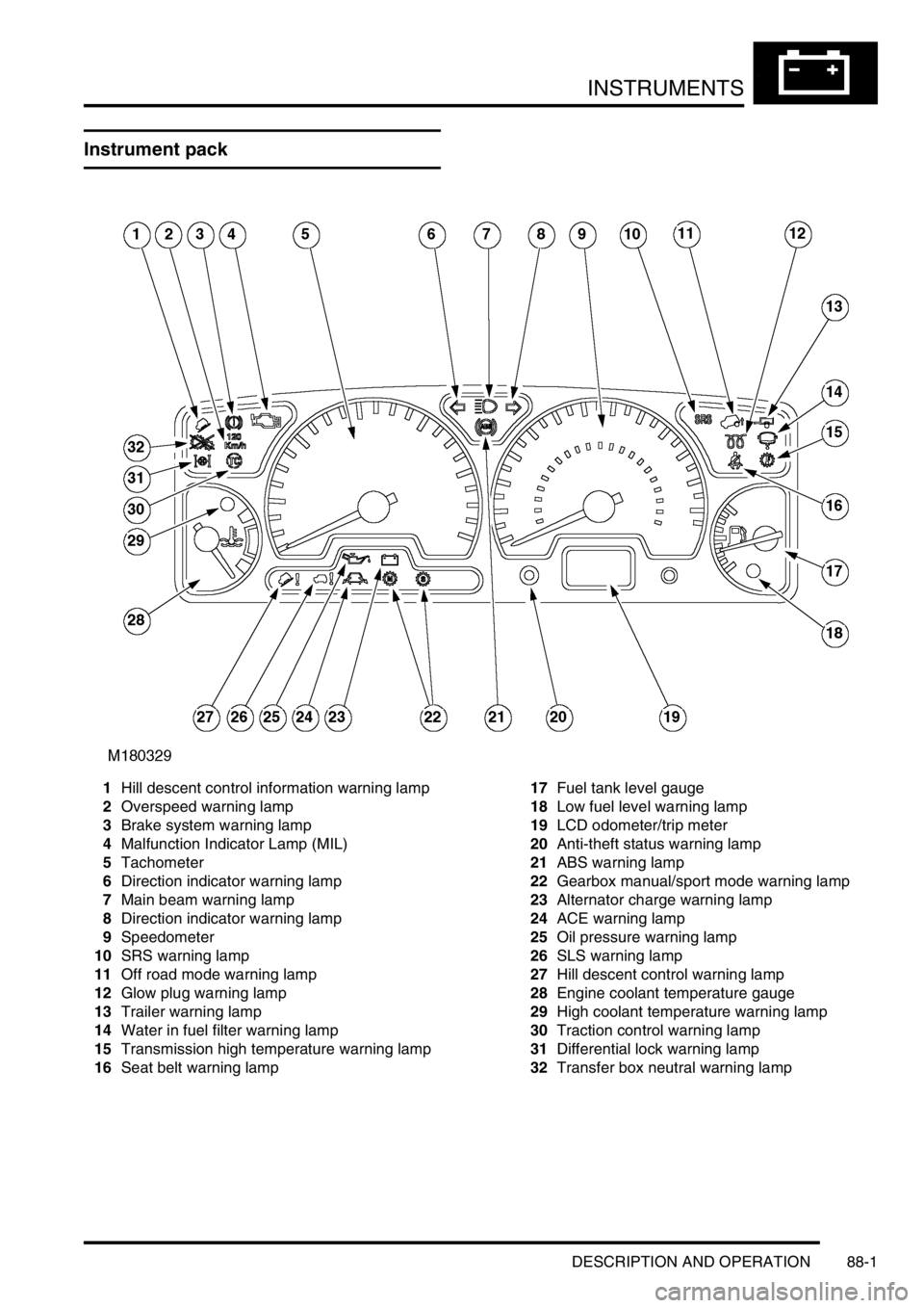
1Hill descent control information warning lamp
2Overspeed warning lamp
3Brake system warning lamp
4Malfunction Indicator Lamp (MIL)
5Tachometer
6Direction indicator warning lamp
7Main beam warning lamp
8Direction indicator warning lamp
9Speedometer
10SRS warning lamp
11Off road mode warning lamp
12Glow plug warning lamp
13Trailer warning lamp
14Water in fuel filter warning lamp
15Transmission high temperature warning lamp
16Seat belt warning lamp17Fuel tank level gauge
18Low fuel level warning lamp
19LCD odometer/trip meter
20Anti-theft status warning lamp
21ABS warning lamp
22Gearbox manual/sport mode warning lamp
23Alternator charge warning lamp
24ACE warning lamp
25Oil pressure warning lamp
26SLS warning lamp
27Hill descent control warning lamp
28Engine coolant temperature gauge
29High coolant temperature warning lamp
30Traction control warning lamp
31Differential lock warning lamp
32Transfer box neutral warning lamp
Page 1632 of 1672

INSTRUMENTS
DESCRIPTION AND OPERATION 88-5
Description
General
The instrument pack consists of four analogue dials, four warning lamp packs and a Liquid Crystal Display (LCD)
odometer.
The four dials are used to indicate:
lRoad speed.
lEngine speed.
lFuel tank level.
lEngine coolant temperature.
The dials are driven by a microprocessor from information received from the serial communication link. Information
input is received as either:
lDigital.
lAnalogue.
lPulse train.
lPulse Width Modulation (PWM).
The LCD provides information for:
lOdometer.
lTrip distance.
lSelected gear (on vehicles fitted with an automatic gearbox).
A trip reset button is provided to zero the trip display, this button also allows the selection of "miles" or "kilometres"
for the display. A photocell controls the illumination of the LCD, maintaining contrast of the display during ambient light
changes.
Within the four warning lamp packs there are 28 lamps. A long life bulb illuminates the high beam warning lamp and
the rest of the warning lamps are illuminated by Light Emitting Diodes (LED's). All warning lamp legends are invisible
until lit. When lit the symbols are illuminated on a black background.
The warning lamps illuminate in one of four colours. The colour indicates the level of importance to the driver, as
follows:
lRed = warning.
lAmber = caution.
lGreen = system operative.
lBlue = main beam operative.
The first warning lamp pack is located in the top left-hand side of the instrument pack and contains the following
warning lamps:
lTraction control warning lamp.
lTransfer box in neutral warning lamp.
lDifferential lock warning lamp
lOverspeed warning lamp (activated for gulf market only).
lBrake system warning lamp.
lHill Descent Control (HDC) information warning lamp.
lMalfunction Indicator Lamp (MIL)/ SERVICE ENGINE SOON warning lamp.
The second warning lamp pack is located in the centre of the instrument pack and contains the following warning
lamps:
lDirection indicator warning lamps.
lHigh beam warning lamp.
lAnti-lock brake system warning lamp.