2002 ISUZU AXIOM ignition
[x] Cancel search: ignitionPage 1829 of 2100
ENTERTAINMENT8C±17
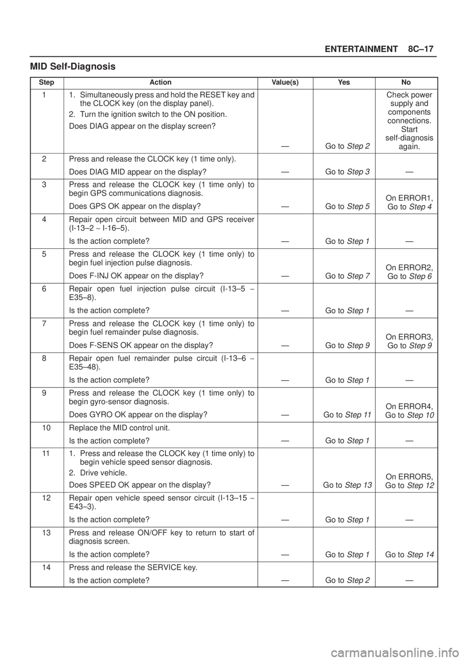
MID Self-Diagnosis
StepActionValue(s)Ye sNo
11. Simultaneously press and hold the RESET key and
the CLOCK key (on the display panel).
2. Turn the ignition switch to the ON position.
Does DIAG appear on the display screen?
ÐGo to Step 2
Check power
supply and
components
connections.
Start
self-diagnosis
again.
2Press and release the CLOCK key (1 time only).
Does DIAG MID appear on the display?
ÐGo to Step 3Ð
3Press and release the CLOCK key (1 time only) to
begin GPS communications diagnosis.
Does GPS OK appear on the display?
ÐGo to Step 5
On ERROR1,
Go to
Step 4
4Repair open circuit between MID and GPS receiver
(I-13±2 ~ I-16±5).
Is the action complete?
ÐGo to Step 1Ð
5Press and release the CLOCK key (1 time only) to
begin fuel injection pulse diagnosis.
Does F-INJ OK appear on the display?
ÐGo to Step 7
On ERROR2,
Go to
Step 6
6Repair open fuel injection pulse circuit (I-13±5 ~
E35±8).
Is the action complete?
ÐGo to Step 1Ð
7Press and release the CLOCK key (1 time only) to
begin fuel remainder pulse diagnosis.
Does F-SENS OK appear on the display?
ÐGo to Step 9
On ERROR3,
Go to
Step 9
8Repair open fuel remainder pulse circuit (I-13±6 ~
E35±48).
Is the action complete?
ÐGo to Step 1Ð
9Press and release the CLOCK key (1 time only) to
begin gyro-sensor diagnosis.
Does GYRO OK appear on the display?
ÐGo to Step 11
On ERROR4,
Go to
Step 10
10Replace the MID control unit.
Is the action complete?
ÐGo to Step 1Ð
111. Press and release the CLOCK key (1 time only) to
begin vehicle speed sensor diagnosis.
2. Drive vehicle.
Does SPEED OK appear on the display?
ÐGo to Step 13
On ERROR5,
Go to
Step 12
12Repair open vehicle speed sensor circuit (I-13±15 ~
E43±3).
Is the action complete?
ÐGo to Step 1Ð
13Press and release ON/OFF key to return to start of
diagnosis screen.
Is the action complete?
ÐGo to Step 1Go to Step 14
14Press and release the SERVICE key.
Is the action complete?
ÐGo to Step 2Ð
Page 1830 of 2100
8C±18ENTERTAINMENT
Symptom Diagnosis
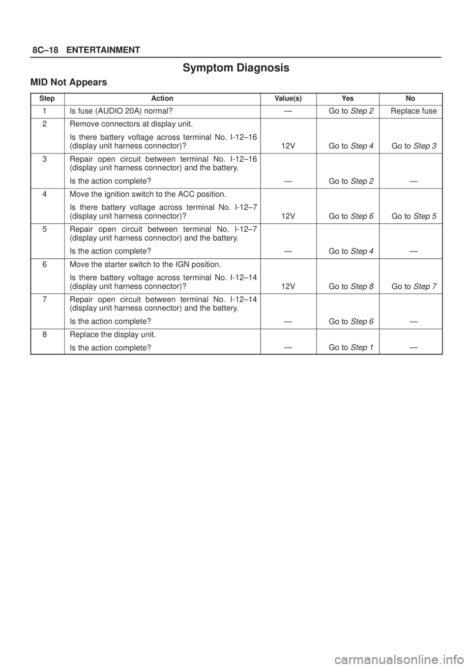
MID Not Appears
StepActionValue(s)Ye sNo
1Is fuse (AUDIO 20A) normal?ÐGo to Step 2Replace fuse
2Remove connectors at display unit.
Is there battery voltage across terminal No. I-12±16
(display unit harness connector)?
12VGo to Step 4Go to Step 3
3Repair open circuit between terminal No. I-12±16
(display unit harness connector) and the battery.
Is the action complete?
ÐGo to Step 2Ð
4Move the ignition switch to the ACC position.
Is there battery voltage across terminal No. I-12±7
(display unit harness connector)?
12VGo to Step 6Go to Step 5
5Repair open circuit between terminal No. I-12±7
(display unit harness connector) and the battery.
Is the action complete?
ÐGo to Step 4Ð
6Move the starter switch to the IGN position.
Is there battery voltage across terminal No. I-12±14
(display unit harness connector)?
12VGo to Step 8Go to Step 7
7Repair open circuit between terminal No. I-12±14
(display unit harness connector) and the battery.
Is the action complete?
ÐGo to Step 6Ð
8Replace the display unit.
Is the action complete?
ÐGo to Step 1Ð
Page 1831 of 2100
ENTERTAINMENT8C±19
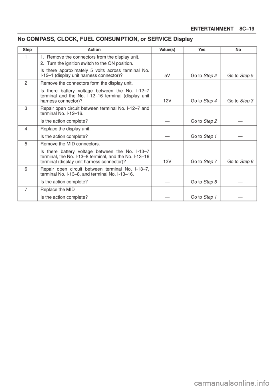
No COMPASS, CLOCK, FUEL CONSUMPTION, or SERVICE Display
StepActionValue(s)Ye sNo
11. Remove the connectors from the display unit.
2. Turn the ignition switch to the ON position.
Is there approximately 5 volts across terminal No.
I-12±1 (display unit harness connector)?
5VGo to Step 2Go to Step 5
2Remove the connectors form the display unit.
Is there battery voltage between the No. I-12±7
terminal and the No. I-12±16 terminal (display unit
harness connector)?
12VGo to Step 4Go to Step 3
3Repair open circuit between terminal No. I-12±7 and
terminal No. I-12±16.
Is the action complete?
ÐGo to Step 2Ð
4Replace the display unit.
Is the action complete?
ÐGo to Step 1Ð
5Remove the MID connectors.
Is there battery voltage between the No. I-13±7
terminal, the No. I-13±8 terminal, and the No. I-13±16
terminal (display unit harness connector)?
12VGo to Step 7Go to Step 6
6Repair open circuit between terminal No. I-13±7,
terminal No. I-13±8, and terminal No. I-13±16.
Is the action complete?
ÐGo to Step 5Ð
7Replace the MID
Is the action complete?
ÐGo to Step 1Ð
Page 1962 of 2100
8H±12SECURITY AND LOCKS
Key
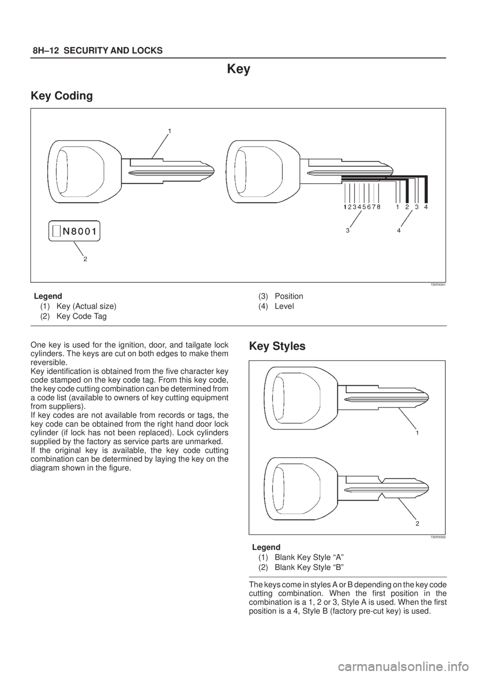
Key Coding
730RX001
Legend
(1) Key (Actual size)
(2) Key Code Tag(3) Position
(4) Level
One key is used for the ignition, door, and tailgate lock
cylinders. The keys are cut on both edges to make them
reversible.
Key identification is obtained from the five character key
code stamped on the key code tag. From this key code,
the key code cutting combination can be determined from
a code list (available to owners of key cutting equipment
from suppliers).
If key codes are not available from records or tags, the
key code can be obtained from the right hand door lock
cylinder (if lock has not been replaced). Lock cylinders
supplied by the factory as service parts are unmarked.
If the original key is available, the key code cutting
combination can be determined by laying the key on the
diagram shown in the figure.Key Styles
730RX002
Legend
(1) Blank Key Style ªAº
(2) Blank Key Style ªBº
The keys come in styles A or B depending on the key code
cutting combination. When the first position in the
combination is a 1, 2 or 3, Style A is used. When the first
position is a 4, Style B (factory pre-cut key) is used.
Page 2018 of 2100
SUPPLEMENTAL RESTRAINT SYSTEM 9J±4
SRS Component and Wiring Location
View
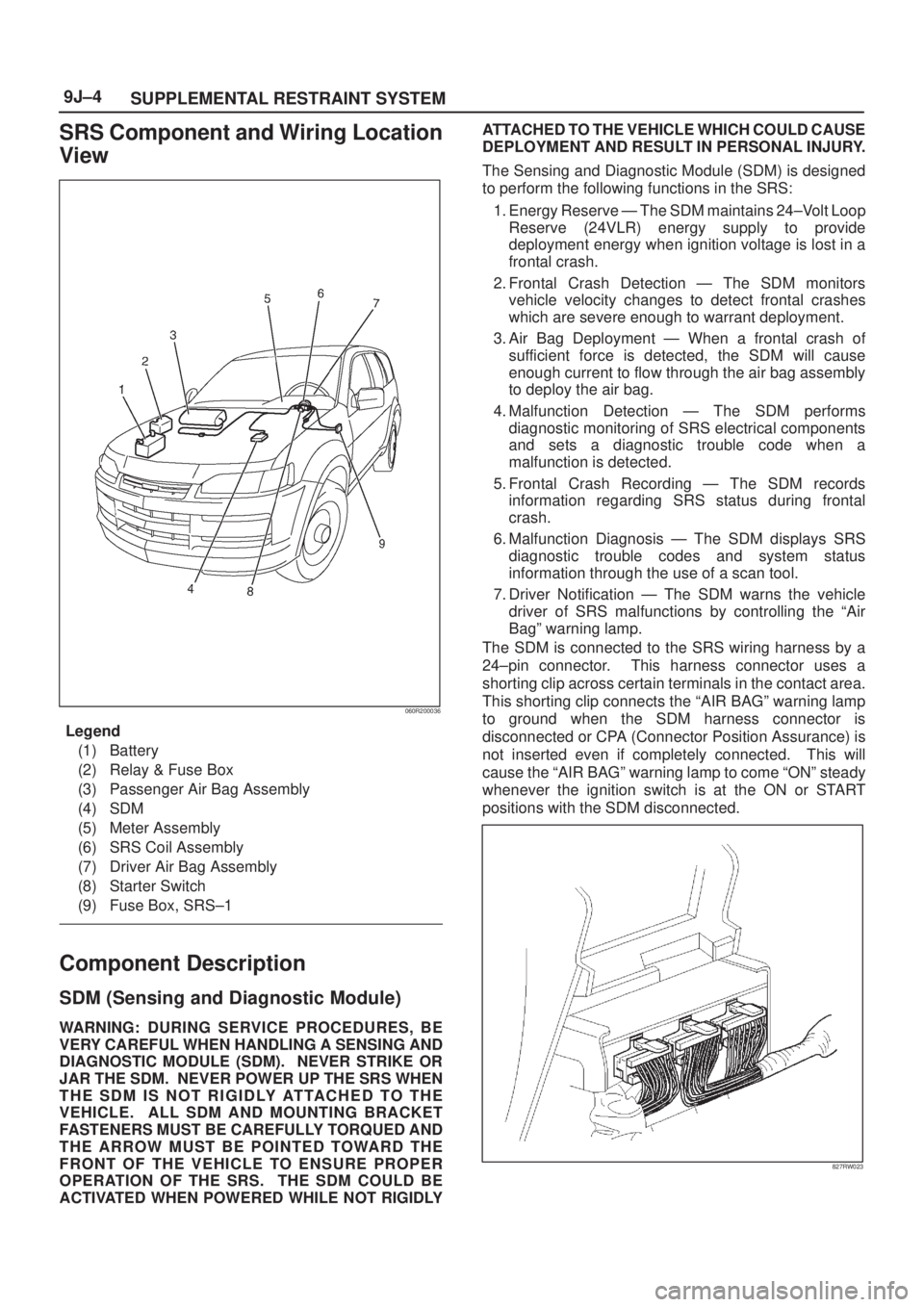
060R200036
Legend
(1) Battery
(2) Relay & Fuse Box
(3) Passenger Air Bag Assembly
(4) SDM
(5) Meter Assembly
(6) SRS Coil Assembly
(7) Driver Air Bag Assembly
(8) Starter Switch
(9) Fuse Box, SRS±1
Component Description
SDM (Sensing and Diagnostic Module)
WARNING:DURING SERVICE PROCEDURES, BE
VERY CAREFUL WHEN HANDLING A SENSING AND
DIAGNOSTIC MODULE (SDM). NEVER STRIKE OR
JAR THE SDM. NEVER POWER UP THE SRS WHEN
THE SDM IS NOT RIGIDLY ATTACHED TO THE
VEHICLE. ALL SDM AND MOUNTING BRACKET
FASTENERS MUST BE CAREFULLY TORQUED AND
THE ARROW MUST BE POINTED TOWARD THE
FRONT OF THE VEHICLE TO ENSURE PROPER
OPERATION OF THE SRS. THE SDM COULD BE
ACTIVATED WHEN POWERED WHILE NOT RIGIDLYATTACHED TO THE VEHICLE WHICH COULD CAUSE
DEPLOYMENT AND RESULT IN PERSONAL INJURY.
The Sensing and Diagnostic Module (SDM) is designed
to perform the following functions in the SRS:
1. Energy Reserve Ð The SDM maintains 24±Volt Loop
Reserve (24VLR) energy supply to provide
deployment energy when ignition voltage is lost in a
frontal crash.
2. Frontal Crash Detection Ð The SDM monitors
vehicle velocity changes to detect frontal crashes
which are severe enough to warrant deployment.
3. Air Bag Deployment Ð When a frontal crash of
sufficient force is detected, the SDM will cause
enough current to flow through the air bag assembly
to deploy the air bag.
4. Malfunction Detection Ð The SDM performs
diagnostic monitoring of SRS electrical components
and sets a diagnostic trouble code when a
malfunction is detected.
5. Frontal Crash Recording Ð The SDM records
information regarding SRS status during frontal
crash.
6. Malfunction Diagnosis Ð The SDM displays SRS
diagnostic trouble codes and system status
information through the use of a scan tool.
7. Driver Notification Ð The SDM warns the vehicle
driver of SRS malfunctions by controlling the ªAir
Bagº warning lamp.
The SDM is connected to the SRS wiring harness by a
24±pin connector. This harness connector uses a
shorting clip across certain terminals in the contact area.
This shorting clip connects the ªAIR BAGº warning lamp
to ground when the SDM harness connector is
disconnected or CPA (Connector Position Assurance) is
not inserted even if completely connected. This will
cause the ªAIR BAGº warning lamp to come ªONº steady
whenever the ignition switch is at the ON or START
positions with the SDM disconnected.
827RW023
Page 2019 of 2100
SUPPLEMENTAL RESTRAINT SYSTEM9J±5
ªAir Bagº Warning Lamp
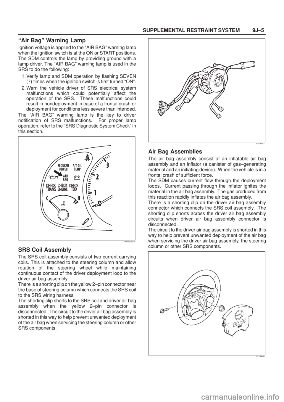
Ignition voltage is applied to the ªAIR BAGº warning lamp
when the ignition switch is at the ON or START positions.
The SDM controls the lamp by providing ground with a
lamp driver. The ªAIR BAGº warning lamp is used in the
SRS to do the following:
1. Verify lamp and SDM operation by flashing SEVEN
(7) times when the ignition switch is first turned ªONº.
2. Warn the vehicle driver of SRS electrical system
malfunctions which could potentially affect the
operation of the SRS. These malfunctions could
result in nondeployment in case of a frontal crash or
deployment for conditions less severe than intended.
The ªAIR BAGº warning lamp is the key to driver
notification of SRS malfunctions. For proper lamp
operation, refer to the ªSRS Diagnostic System Checkº in
this section.
060R200035
SRS Coil Assembly
The SRS coil assembly consists of two current carrying
coils. This is attached to the steering column and allow
rotation of the steering wheel while maintaining
continuous contact of the driver deployment loop to the
driver air bag assembly.
There is a shorting clip on the yellow 2±pin connector near
the base of steering column which connects the SRS coil
to the SRS wiring harness.
The shorting clip shorts to the SRS coil and driver air bag
assembly when the yellow 2±pin connector is
disconnected. The circuit to the driver air bag assembly is
shorted in this way to help prevent unwanted deployment
of the air bag when servicing the steering column or other
SRS components.
825RS071
Air Bag Assemblies
The air bag assembly consist of an inflatable air bag
assembly and an inflator (a canister of gas±generating
material and an initiating device). When the vehicle is in a
frontal crash of sufficient force.
The SDM causes current flow through the deployment
loops. Current passing through the inflator ignites the
material in the air bag assembly. The gas produced from
this reaction rapidly inflates the air bag assembly.
There is a shorting clip on the driver air bag assembly
connector which connects the SRS coil assembly. The
shorting clip shorts across the driver air bag assembly
circuits when driver air bag assembly connector is
disconnected.
The circuit to the driver air bag assembly is shorted in this
way to help prevent unwanted deployment of the air bag
when servicing the driver air bag assembly, the steering
column or other SRS components.
827RX001
Page 2020 of 2100
SUPPLEMENTAL RESTRAINT SYSTEM 9J±6
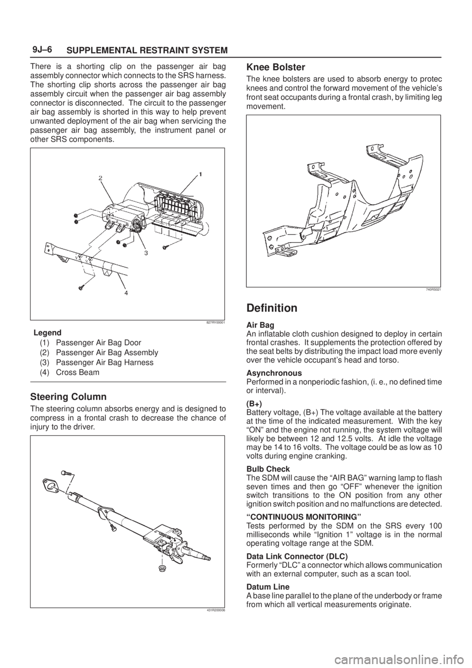
There is a shorting clip on the passenger air bag
assembly connector which connects to the SRS harness.
The shorting clip shorts across the passenger air bag
assembly circuit when the passenger air bag assembly
connector is disconnected. The circuit to the passenger
air bag assembly is shorted in this way to help prevent
unwanted deployment of the air bag when servicing the
passenger air bag assembly, the instrument panel or
other SRS components.
827RY00001
Legend
(1) Passenger Air Bag Door
(2) Passenger Air Bag Assembly
(3) Passenger Air Bag Harness
(4) Cross Beam
Steering Column
The steering column absorbs energy and is designed to
compress in a frontal crash to decrease the chance of
injury to the driver.
431R200006
Knee Bolster
The knee bolsters are used to absorb energy to protec
knees and control the forward movement of the vehicle's
front seat occupants during a frontal crash, by limiting leg
movement.
740RS021
Definition
Air Bag
An inflatable cloth cushion designed to deploy in certain
frontal crashes. It supplements the protection offered by
the seat belts by distributing the impact load more evenly
over the vehicle occupant's head and torso.
Asynchronous
Performed in a nonperiodic fashion, (i. e., no defined time
or interval).
(B+)
Battery voltage, (B+) The voltage available at the battery
at the time of the indicated measurement. With the key
ªONº and the engine not running, the system voltage will
likely be between 12 and 12.5 volts. At idle the voltage
may be 14 to 16 volts. The voltage could be as low as 10
volts during engine cranking.
Bulb Check
The SDM will cause the ªAIR BAGº warning lamp to flash
seven times and then go ªOFFº whenever the ignition
switch transitions to the ON position from any other
ignition switch position and no malfunctions are detected.
ªCONTINUOUS MONITORINGº
Tests performed by the SDM on the SRS every 100
milliseconds while ªIgnition 1º voltage is in the normal
operating voltage range at the SDM.
Data Link Connector (DLC)
Formerly ªDLCº a connector which allows communication
with an external computer, such as a scan tool.
Datum Line
A base line parallel to the plane of the underbody or frame
from which all vertical measurements originate.
Page 2021 of 2100
SUPPLEMENTAL RESTRAINT SYSTEM9J±7
Deploy
To inflate the air bag.
Deployment Loops
The circuits which supply current to the air bag
assemblies to deploy the air bag.
Diagnostic Trouble Code (DTC)
Formerly ªCodeº, a numerical designator used by the
SDM to indicate specific SRS malfunctions.
Driver Current Source
An output of the SDM which applies current into the driver
air bag assembly circuit during the ªInitiator Assembly
Resistance Testº.
Driver Air Bag Assembly
An assembly located in the steering wheel hub consisting
of an inflatable bag, an inflator and an initiator.
EEPROM
Electronically Erasable Programmable Read Only
Memory. Memory which retains its contents when power
is removed from the SDM.
Ignition Cycle
The voltage at the SDM ªIgnition 1º inputs, with ignition
switch ªONº, is within the normal operating voltage range
for at least ten seconds before turning ignition switch
ªOFFº.
Ignition 1
A battery voltage (B+) circuit which is only powered with
the ignition switch in the ON, or START positions.
Initiator
The electrical component inside the air bag assembly
which, when sufficient current flows, sets off the chemical
reaction that inflates the air bag.
ªInitiator Assembly Resistance Testº
Tests performed once each ignition cycle when no
malfunctions are detected during ªTurn±ONº or
ªContinuous Monitoring.º This test checks for the correct
SDM configuration for the vehicle, shorts to ªIgnition 1º in
the deployment loops, high resistance or opens in the
ªDriver Side Highº, ªDriver Side Lowº, ªPassenger Side
Highº and ªPassenger Side Lowº circuits and measures
the resistance of the inflator assembly consisting of: 1)
Initiators, 2) SRS coil assembly (driver side only), 3)
Connectors and associated wiring.
Normal Operating Voltage Range
The voltage measured between the SDM ªIgnition 1º
terminals and ªGroundº terminals is between 9 and 16
volts.
Passenger Current Source
An output of the SDM which applies current into the
passenger air bag assembly circuit during the ªInitiator
Assembly Resistance Testº.
Passenger Air Bag Assembly
An assembly located in the right side of the instrument
panel consisting of an inflatable bag, an inflator and an
initiator.
Scan Tool
An external computer used to read diagnostic information
from onboard computers via the data link connector.SDM
Sensing and Diagnostic Module which provides reserve
energy to the deployment loops, deploys the air bags
when required and performs diagnostic monitoring of all
SRS components.
Serial Data
Information representing the status of the SRS.
SRS
Supplemental Restraint System.
SRS Coil Assembly
An assembly of two current±carrying coils in the driver
deployment loop that allows the rotation of the steering
wheel while maintaining the continuous contact of the
driver deployment loop to the driver air bag assembly.
SRS Wiring Harness
The wires and connectors that electrically connect the
components in the SRS.
ªTurn±ONº
Test which the SDM performs on the SRS once during
each ignition cycle immediately after ªIgnition 1º voltage
is applied to the SDM and before ªContinuous
Monitoringº.
Diagnosis
WARNING: T O AV O I D D E P L O Y M E N T W H E N
TROUBLESHOOTING THE SRS, DO NOT USE
ELECTRICAL TEST EQUIPMENT SUCH AS A
BATTERY±POWERED OR AC±POWERED
VOLTMETER, OHMMETER, ETC., OR ANY TYPE OF
ELECTRICAL EQUIPMENT OTHER THAN THAT
SPECIFIED IN THIS MANUAL. DO NOT USE A
NON±POWERED PROVE±TYPE TESTER.
INSTRUCTIONS IN THIS MANUAL MUST BE
FOLLOWED CAREFULLY, OTHERWISE PERSONAL
INJURY MAY RESULT.
Diagnostic Trouble Codes
The ªSRS Diagnostic System Checkº must always be the
starting point of any SRS diagnosis. The ªSRS
Diagnostic System Checkº checks for proper ªAIR BAGº
warning lamp operation and checks for SRS diagnostic
trouble codes using the scan tool.
1. Current diagnostic trouble codes ± Malfunctions that
are presently being detected. Current diagnostic
trouble codes are stored in RAM (Random Access
Memory).
2. History diagnostic trouble codes ± All malfunctions
detected since the last time the history memory was
cleared. History diagnostic trouble codes are stored
in EEPROM.
Scan Tool Diagnostics
A scan tool is used to read current and history diagnostic
trouble codes and to clear all diagnostic trouble codes
after a repair is completed. The scan tool must be
updated to communicate with the SRS through a
replaceable cartridge before it can be used for SRS
diagnostics. To use the scan tool, connect it to the data
link connector and turn the ignition switch ªONº. The scan