Page 1827 of 2100
Ye sNo
11. Simultaneously press and hold the RESET key and
the CLOCK key (on the display panel).
2. Turn the ignition switch to the ON posit")
ENTERTAINMENT8C±15
Audio Self-Diagnosis
StepActionValue(s)Ye sNo
11. Simultaneously press and hold the RESET key and
the CLOCK key (on the display panel).
2. Turn the ignition switch to the ON position.
Does DIAG appear on the display screen?
ÐGo to Step 2
Check power
supply and
component
connections.
Start
self-diagnosis
again.
2Press and release the SERVICE key (1 time only).
Does DIAG AUDIO appear on the display?
ÐGo to Step 3Go to Step 11
3Press and release the SERVICE key (1 time only) to
check tape connections.
Does TAPE OK appear on the display?
ÐGo to Step 4
On NG display,
Go to
Step 11
4Press and release the SERVICE key (1 time only) to
check CD changer connections.
Does CD CHG OK appear on the display?
ÐGo to Step 5
On NG display,
Go to
Step 11
5Press and release the SERVICE key (1 time only) to
check communication with A/C unit.
Does A/C DATA OK appear on the display?
ÐGo to Step 9
On NG display,
Go to
Step 6
6Is A/C DATA ERR1(abnormal display data line)
displayed?
Ð
Refer to A/C
self-diagnosis
Go to Step 7
7Is A/C DATA ERR2 (abnormal CLOCK data line)
displayed?
Ð
Refer to A/C
self-diagnosis
Go to Step 8
8Is A/C DATA ER3 (abnormal SW data line) displayed?ÐGo to Step 11Ð
9Press and release the SERVICE key (1 time only) to
display the A/C unit error history.
Is the action complete?
ÐGo to Step 10Ð
101. Press and release the SERVICE key (1 time only) to
change to the key diagnosis mode.
2. Press and release each key.
NOTE: As a key is pressed, its name should appear on
the display. The A/C LED should blink at 1±second
intervals.
Did the events described in Step 2 occur?
ÐGo to Step 12Go to Step 11
11Replace the audio unit.
Is the action complete?
ÐGo to Step 1Ð
12Press and release the ON/OFF key.
Is the action complete?
ÐGo to Step 1Go to Step 13
13Press and release the SERVICE key (1 time only).
Is the action complete?
ÐGo to Step 3Ð
Page 1981 of 2100
EXTERIOR/INTERIOR TRIM8J±3
Consoles
Consoles and Associated Parts
745R200005
Legend
(1) Cluster Upper Cover
(2) Center Cluster
(3) Knee Pad
(4) Seat Heater Switch (Required Option)
(5) Rear Console Assembly(6) CD Changer
(7) Rear Console Bracket
(8) Front Console Bracket
(9) Front Console Assembly
(10) Accessory Socket
Removal
1. Disconnect the battery ground cable.
2. Remove the cluster upper cover and connectors.
3. Pry the knee pads.
4. Remove the center cluster.
�Remove the six screws and pull out the center
cluster at the six clip positions.�Disconnect the connectors.
5. Remove the rear console assembly.
�Open the rear console lid and remove two screws.
6. Remove the front console assembly.
�Remove six fixing screws and disconnect the
accessory socket connectors.
�Disconnect the seat heater switch connectors (if so
equipped).
Page 1982 of 2100
8J±4EXTERIOR/INTERIOR TRIM
7. Remove the CD changer.
�Remove the four fixing bolts and the connector.Installation
To install, follow the removal steps in the reverse order.
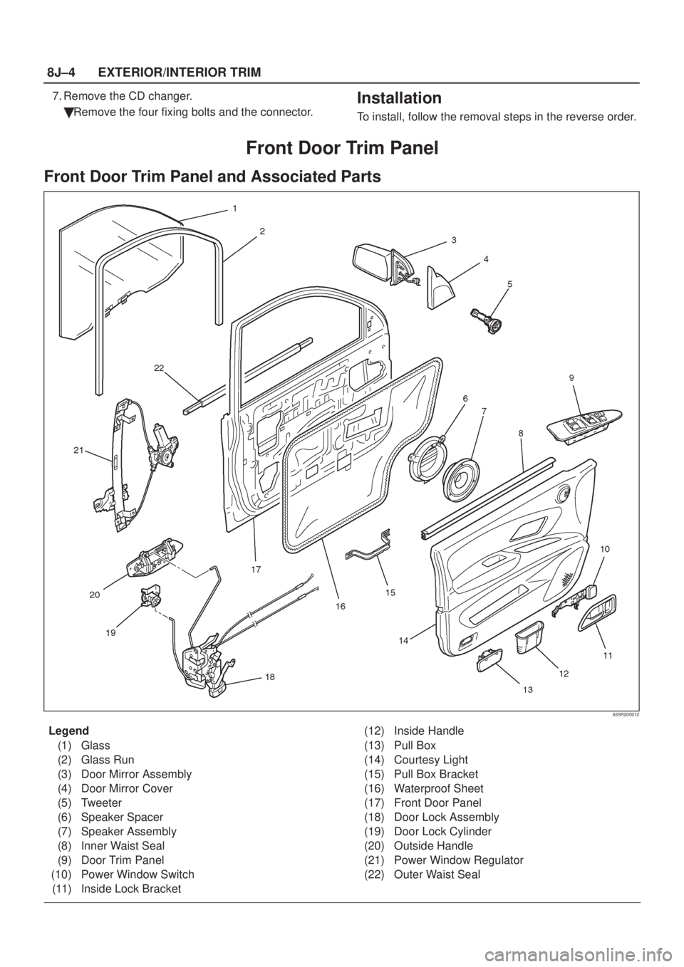
Front Door Trim Panel
Front Door Trim Panel and Associated Parts
635R200012
Legend
(1) Glass
(2) Glass Run
(3) Door Mirror Assembly
(4) Door Mirror Cover
(5) Tweeter
(6) Speaker Spacer
(7) Speaker Assembly
(8) Inner Waist Seal
(9) Door Trim Panel
(10) Power Window Switch
(11) Inside Lock Bracket(12) Inside Handle
(13) Pull Box
(14) Courtesy Light
(15) Pull Box Bracket
(16) Waterproof Sheet
(17) Front Door Panel
(18) Door Lock Assembly
(19) Door Lock Cylinder
(20) Outside Handle
(21) Power Window Regulator
(22) Outer Waist Seal
 Cluster Upper Cover
(2) Center Cluster
(3) Knee Pad
(4) Seat Heater Switch (Required Option)
(5) Rear Console A")