Page 2033 of 2100

SUPPLEMENTAL RESTRAINT SYSTEM9J±19
J±39200 DVM
The J±39200 DVM is the preferred DVM for use in SRS
diagnosis and repair. However, J±34029±A may be used
if J±39200 is not available. No other DVMs are approved
for SRS diagnosis and repair.
901RS153
Scan Tool
The Tech 2 is used to read and clear SRS Diagnostic
Trouble Codes (DTCs). Refer to the Tech 2 Operator's
Manual for specific information on how to use the Tech 2.
901RW176
J±35616±A Connector Test Adapter Kit
The J±35616±A Connector Test Adapter Kit must be used
whenever a diagnostic procedure requests checking or
probing a terminal. Using the appropriate adapter will
ensure that no damage to the terminal will occur from the
DVM prove, such as spreading or bending. The adapter
will also give an idea of whether contact tension is
sufficient, helping to find an open or intermittent open due
to poor terminal contact.
901RS151
J±42986 SRS Deployment Tool
The J±42986 SRS Deployment Tool must be used for
deployment of the undeployed air bag.
901RW106
Page 2034 of 2100
SUPPLEMENTAL RESTRAINT SYSTEM 9J±20
J±42987 SRS Adapter For Load Tool
The J±42987 SRS Adapter be used for connect previous
load tool to new SRS system when inspect SRS system
harness.
901RW107
J±41497 SRS Deployment Fixture
The J±41497 SRS Deployment Fixture must be used for
deployment of the undeployed passenger side air bag.
901RW088
Page 2035 of 2100
SUPPLEMENTAL RESTRAINT SYSTEM9J±21
Tech 2 Scan Tool
From 2002 AXIOM (UP), dealer service departments are
recommended to use Tech 2. Please refer to Tech 2 scan
tool user guide.
901RW180
Legend
(1) PCMCIA Card
(2) RS 232 Loop Back Connector(3) SAE 16/19 Adaptor
(4) DLC Cable
(5) Tech±2
Page 2036 of 2100
SUPPLEMENTAL RESTRAINT SYSTEM 9J±22
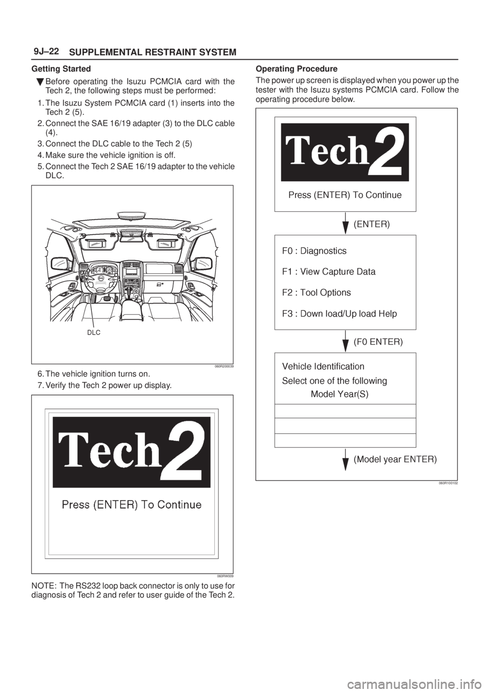
Getting Started
�Before operating the Isuzu PCMCIA card with the
Tech 2, the following steps must be performed:
1. The Isuzu System PCMCIA card (1) inserts into the
Tech 2 (5).
2. Connect the SAE 16/19 adapter (3) to the DLC cable
(4).
3. Connect the DLC cable to the Tech 2 (5)
4. Make sure the vehicle ignition is off.
5. Connect the Tech 2 SAE 16/19 adapter to the vehicle
DLC.
060R200039
6. The vehicle ignition turns on.
7. Verify the Tech 2 power up display.
060RW009
NOTE: The RS232 loop back connector is only to use for
diagnosis of Tech 2 and refer to user guide of the Tech 2.Operating Procedure
The power up screen is displayed when you power up the
tester with the Isuzu systems PCMCIA card. Follow the
operating procedure below.
060R100102
Page 2037 of 2100
SUPPLEMENTAL RESTRAINT SYSTEM9J±23
060R200037
Page 2038 of 2100
SUPPLEMENTAL RESTRAINT SYSTEM 9J±24
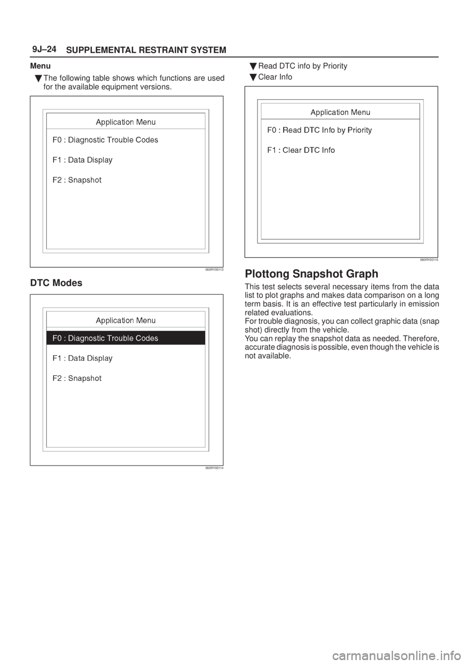
Menu
�The following table shows which functions are used
for the available equipment versions.
060RY00113
DTC Modes
060RY00114
�Read DTC info by Priority
�Clear Info
060RY00115
Plottong Snapshot Graph
This test selects several necessary items from the data
list to plot graphs and makes data comparison on a long
term basis. It is an effective test particularly in emission
related evaluations.
For trouble diagnosis, you can collect graphic data (snap
shot) directly from the vehicle.
You can replay the snapshot data as needed. Therefore,
accurate diagnosis is possible, even though the vehicle is
not available.
Page 2039 of 2100
SUPPLEMENTAL RESTRAINT SYSTEM9J±25
Plotting Graph Flow Chart (Plotting graph after obtaining vehicle information)
060RX041
Page 2040 of 2100
SUPPLEMENTAL RESTRAINT SYSTEM 9J±26
Flow Chart for Snapshot Replay (Plotting Graph)
060RX040

, dealer service departments are
recommended to use Tech 2. Please refer to Tech 2 scan
tool user guide.
901RW180
Legend
(1) PC")


060RX041")

060RX040")