Page 2009 of 2100
9A±8SEAT BELT SYSTEM
Rear Center Seat Belt / Buckle Assembly
Rear Center Seat Belt / Buckle Assembly and Associated Parts
755R200006
Legend
(1) Rear Seat Lock Assembly(2) Rear Seat Belt Buckle Assembly
(3) Rear Cushion Frame Assembly
Removal
1. Remove the rear cushion frame assembly.
�Refer to Rear Seat Assembly in Seats section.
2. Remove the rear seat lock assembly and rear seat
belt buckle assembly.
Installation
To install, follow the removal steps in the reverse order,
noting the following point.
1. Tighten the rear seat lock assembly and rear seat belt
buckle assembly fixing bolts to the specified torque.
Torque: 39 N´m (29 lb ft)
NOTE: Removal and installation procedure of rear center
seat belt assembly same as rear seat belt buckle
assembly procedures.
Page 2010 of 2100
SEAT BELT SYSTEM9A±9
Child Seat Tether Anchorage Bracket (Child Restraint)
Child Seat Tether Anchorage Bracket and Associated Parts
760R200010
Legend
(1) Rear Seat
(2) Luggage Floor Carpet
(3) Tether Anchorage Bracket Cover(4) Child Seat Tether Anchorage Bracket
(5) Luggage Floor Panel
(6) Insulation
Removal
1. Open the tether anchorage bracket cover.
2. Remove the fixing bolt and child seat tether
anchorage bracket.
Installation
To install, follow the removal steps in the reverse order,
noting the following points.
1. Install the bracket such that its tether belt hook hole is
facing toward the front of the vehicle.
2. Tighten the fixing bolts to the specified torque.
Torque: 19 N´m (14 lb ft)
Page 2011 of 2100
9A±10SEAT BELT SYSTEM
Child Seat Lower Anchorage Striker
Child Seat Lower Anchorage Striker
and Associated Parts
755R200007
Legend
(1) Rear Seat Back Assembly
(2) Release Knob
(3) Headrest
(4) Front Luggage Floor Carpet(5) Seat Lock Cover
(6) Lower Anchorage Striker (LH)
(7) Lower Anchorage Striker (RH)
(8) Body Floor Panel
(9) Rear Seat Cushion Assembly
Removal
1. Raise the seat cushion assembly (2).
�Pull the strap (1) of the rear seat lock assembly to
release the seat lock.
755R100006
Page 2012 of 2100
SEAT BELT SYSTEM9A±11
2. Remove the headrests.
3. Pull the release knobs and fall down the seat back
assembly forward.
4. Remove the seat lock covers.
�Remove the three fixing screws from each seat lock
cover.
5. Remove the front luggage floor carpets.
�Pull the nine carpet fixing clips from the backside of
the seat back assembly.
6. Remove the four lower anchorage strikers.
�Remove the two fixing bolts of each lower
anchorage striker.
Installation
To install, follow the removal steps in the reverse order,
noting the following points.
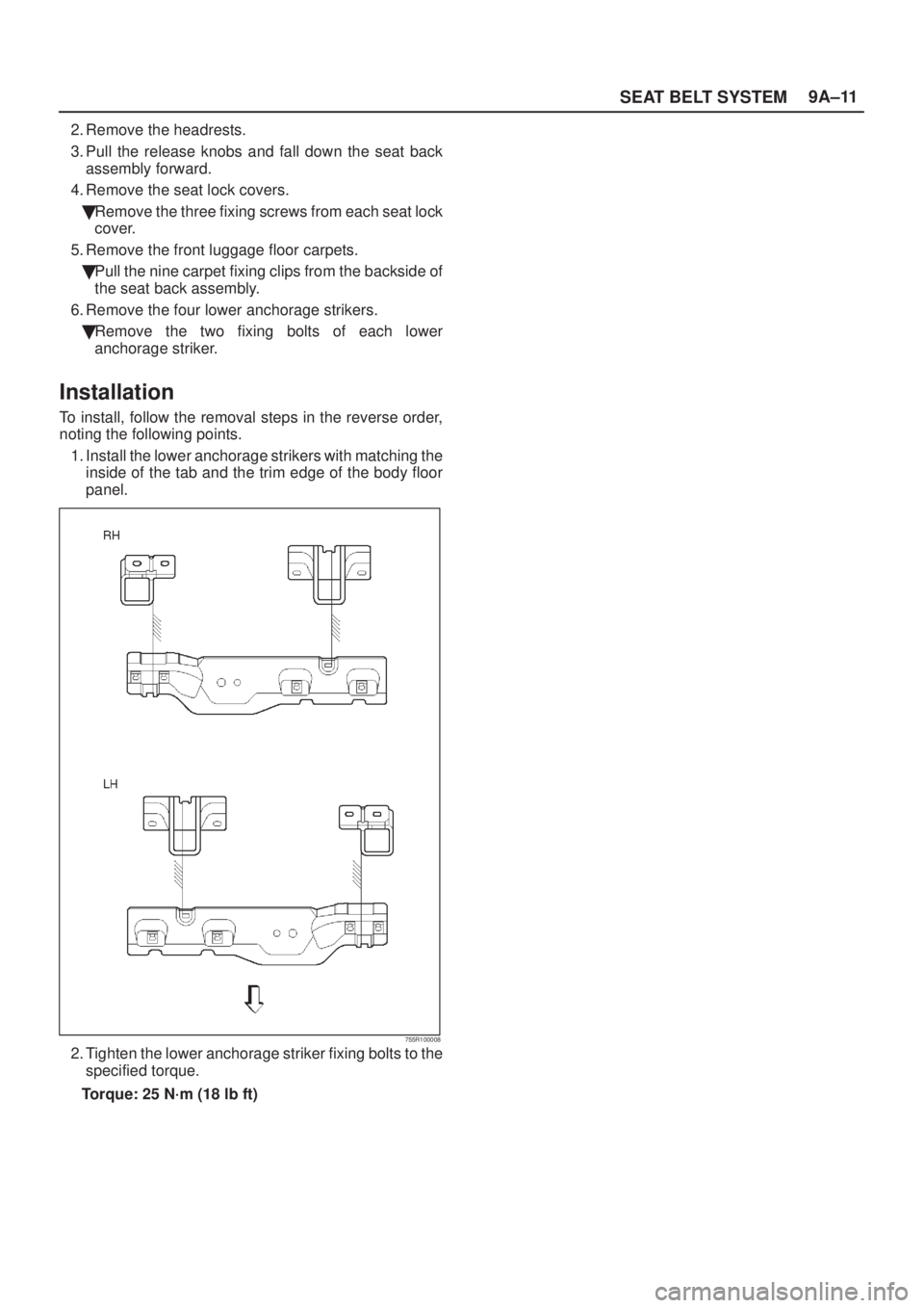
1. Install the lower anchorage strikers with matching the
inside of the tab and the trim edge of the body floor
panel.
755R100008
2. Tighten the lower anchorage striker fixing bolts to the
specified torque.
Torque: 25 N´m (18 lb ft)
Page 2013 of 2100
9A±12SEAT BELT SYSTEM
Main Data and Specifications
Torque Specifications
760R200018
Page 2014 of 2100
SEAT BELT SYSTEM9A±13
760R200012
Page 2015 of 2100

CONTENTS
Service Precaution 9J±2. . . . . . . . . . . . . . . . . . . . . .
General Description 9J±2. . . . .")
SUPPLEMENTAL RESTRAINT SYSTEM9J±1
AXIOM
RESTRAINTS
SUPPLEMENTAL RESTRAINT SYSTEM (SRS)
CONTENTS
Service Precaution 9J±2. . . . . . . . . . . . . . . . . . . . . .
General Description 9J±2. . . . . . . . . . . . . . . . . . . . .
Restraint Devices 9J±2. . . . . . . . . . . . . . . . . . . . . .
System Description 9J±3. . . . . . . . . . . . . . . . . . . .
SRS Component and Wiring Location View 9J±4
Component Description 9J±4. . . . . . . . . . . . . . . . . .
SDM (Sensing and Diagnostic Module) 9J±4. . .
ªAir Bagº Warning Lamp 9J±5. . . . . . . . . . . . . . . .
SRS Coil Assembly 9J±5. . . . . . . . . . . . . . . . . . . .
Air Bag Assemblies 9J±5. . . . . . . . . . . . . . . . . . . .
Steering Column 9J±6. . . . . . . . . . . . . . . . . . . . . .
Knee Bolster 9J±6. . . . . . . . . . . . . . . . . . . . . . . . . .
Definition 9J±6. . . . . . . . . . . . . . . . . . . . . . . . . . . . . . .
Diagnosis 9J±7. . . . . . . . . . . . . . . . . . . . . . . . . . . . . .
Diagnostic Trouble Codes 9J±7. . . . . . . . . . . . . .
Scan Tool Diagnostics 9J±7. . . . . . . . . . . . . . . . . .
Use of Special Tools 9J±8. . . . . . . . . . . . . . . . . . .
SRS Connector Body Face Views 9J±8. . . . . . . . .
Repairs and Inspections Required After an
Accident 9J±8. . . . . . . . . . . . . . . . . . . . . . . . . . . . . . .
Accident With Deployment ± Component
Replacement and Inspections 9J±9. . . . . . . . . .
Accident With or Without
DeploymentÐComponent Inspection 9J±9. . . .
SDM Replacement Guidelines 9J±9. . . . . . . . . .
Wiring Damage 9J±9. . . . . . . . . . . . . . . . . . . . . . .
SRS Connector (Plastic Body And
Terminal Metal Pin) Damage 9J±9. . . . . . . . . . .
SRS Wire Pigtail Damage 9J±9. . . . . . . . . . . . . .
On±Vehicle Service 9J±9. . . . . . . . . . . . . . . . . . . . . .
Service Precautions 9J±9. . . . . . . . . . . . . . . . . . .
Disabling The SRS 9J±9. . . . . . . . . . . . . . . . . . . .
Enabling The SRS 9J±9. . . . . . . . . . . . . . . . . . . . .
Handling / Installation / Diagnosis 9J±10. . . . . . . .
Air Bag Assembly Handling / Shipping
/ Scrapping 9J±10. . . . . . . . . . . . . . . . . . . . . . . . . . . .
Live (Undeployed) Air Bag Assembly 9J±10. . . . .
Air Bag Assembly Shipping Procedure For
Live (Undeployed) Air Bag Assemblies 9J±11. . .
Deployed Air Bag Assembly 9J±11. . . . . . . . . . . .
Air Bag Assembly Scrapping Procedure 9J±11. .
Deployment Outside Vehicle
(Driver Air Bag Assembly) 9J±11. . . . . . . . . . . . . .
Deployment Outside Vehicle
(Passenger Air Bag Assembly) 9J±13. . . . . . . . . Deployment Inside Vehicle
(Vehicle Scrapping Procedure) 9J±15. . . . . . . . . .
Deployed Air Bag Assembly Handling 9J±18. . . .
Special Tools 9J±18. . . . . . . . . . . . . . . . . . . . . . . . . . .
J±41433 SRS Driver/Passenger Load Tool 9J±18
J±39200 DVM 9J±19. . . . . . . . . . . . . . . . . . . . . . . . .
Scan Tool 9J±19. . . . . . . . . . . . . . . . . . . . . . . . . . . . .
J±35616±A Connector Test Adapter Kit 9J±19. . .
J±42986 SRS Deployment Tool 9J±19. . . . . . . . .
J±42987 SRS Adapter For Load Tool 9J±20. . . . .
J±41497 SRS Deployment Fixture 9J±20. . . . . . .
Tech 2 Scan Tool 9J±21. . . . . . . . . . . . . . . . . . . . . .
DTC Modes 9J±24. . . . . . . . . . . . . . . . . . . . . . . . . . .
Plottong Snapshot Graph 9J±24. . . . . . . . . . . . . . . . .
Plotting Graph Flow Chart (Plotting graph
after obtaining vehicle information) 9J±25. . . . . .
Flow Chart for Snapshot Replay
(Plotting Graph) 9J±26. . . . . . . . . . . . . . . . . . . . . . .
Service Precaution 9J±27. . . . . . . . . . . . . . . . . . . . . .
Disabling The SRS 9J±27. . . . . . . . . . . . . . . . . . . .
Enabling The SRS 9J±27. . . . . . . . . . . . . . . . . . . . .
Handling / Installation / Diagnosis 9J±27. . . . . . . .
Inspections Required After An Accident 9J±27. .
Sensing and Diagnostic Module (SDM) 9J±28. . . .
Service Precautions 9J±28. . . . . . . . . . . . . . . . . . .
Removal 9J±28. . . . . . . . . . . . . . . . . . . . . . . . . . . . .
Installation 9J±29. . . . . . . . . . . . . . . . . . . . . . . . . . . .
Driver Air Bag Assembly 9J±29. . . . . . . . . . . . . . . . .
Service Precautions 9J±29. . . . . . . . . . . . . . . . . . .
Removal 9J±29. . . . . . . . . . . . . . . . . . . . . . . . . . . . .
Installation 9J±30. . . . . . . . . . . . . . . . . . . . . . . . . . . .
Steering Wheel 9J±30. . . . . . . . . . . . . . . . . . . . . . . . .
Service Precautions 9J±30. . . . . . . . . . . . . . . . . . .
Removal 9J±30. . . . . . . . . . . . . . . . . . . . . . . . . . . . .
Installation 9J±31. . . . . . . . . . . . . . . . . . . . . . . . . . . .
SRS Coil Assembly 9J±32. . . . . . . . . . . . . . . . . . . . . .
Service Precaution 9J±32. . . . . . . . . . . . . . . . . . . .
Removal 9J±32. . . . . . . . . . . . . . . . . . . . . . . . . . . . .
Installation 9J±32. . . . . . . . . . . . . . . . . . . . . . . . . . . .
Steering Column 9J±34. . . . . . . . . . . . . . . . . . . . . . . .
Service Precaution 9J±34. . . . . . . . . . . . . . . . . . . .
Removal 9J±34. . . . . . . . . . . . . . . . . . . . . . . . . . . . .
Installation 9J±35. . . . . . . . . . . . . . . . . . . . . . . . . . . .
Passenger Air Bag Assembly 9J±36. . . . . . . . . . . . .
Service Precaution 9J±36. . . . . . . . . . . . . . . . . . . .
Page 2016 of 2100

SUPPLEMENTAL RESTRAINT SYSTEM 9J±2
Removal 9J±36. . . . . . . . . . . . . . . . . . . . . . . . . . . . . Installation 9J±36. . . . . . . . . . . . . . . . . . . . . . . . . . . .
Service Precaution
WARNING: THIS VEHICLE HAS A SUPPLEMENTAL
RESTRAINT SYSTEM (SRS). REFER TO THE SRS
COMPONENT AND WIRING LOCATION VIEW IN
ORDER TO DETERMINE WHETHER YOU ARE
PERFORMING SERVICE ON OR NEAR THE SRS
COMPONENTS OR THE SRS WIRING. WHEN YOU
ARE PERFORMING SERVICE ON OR NEAR THE SRS
COMPONENTS OR THE SRS WIRING, REFER TO
THE SRS SERVICE INFORMATION. FAILURE TO
FOLLOW WARNINGS COULD RESULT IN POSSIBLE
AIR BAG DEPLOYMENT, PERSONAL INJURY, OR
OTHERWISE UNNEEDED SRS SYSTEM REPAIRS.
CAUTION: Always use the correct fastener in the
proper location. When you replace a fastener, use
ONLY the exact part number for that application.
ISUZU will call out those fasteners that require a
replacement after removal. ISUZU will also call out
the fasteners that require thread lockers or thread
sealant. UNLESS OTHERWISE SPECIFIED, do not
use supplemental coatings (Paints, greases, or other
corrosion inhibitors) on threaded fasteners or
fastener joint interfaces. Generally, such coatings
adversely affect the fastener torque and the joint
clamping force, and may damage the fastener. When
you install fasteners, use the correct tightening
sequence and specifications. Following these
instructions can help you avoid damage to parts and
systems.
General Description
CAUTION: When fasteners are removed, always
reinstall them at the same location from which they
were removed. If a fastener needs to be replaced, use
the correct part number fastener for that application.
If the correct part number fastener is not available, a
fastener of equal size and strength (or stronger) may
be used. fasteners that are not reused, and those
requiring thread locking compound will be called
out. The correct torque value must be used when
installing fasteners that require it. If the above
conditions are not followed, parts or system damage
could result.
Restraint Devices
827RS035
Legend
(1) Deployed Air Bag
(2) Knee Bolster
(3) Seat Belt
The Supplemental Restraint System (SRS) helps
supplement the protection offered by the driver and front
passenger seat belts by deploying an air bag from the
center of the steering wheel and from the top of the right
side of the instrument panel.
The air bag deploys when the vehicle is involved in a
frontal crash of sufficient force up to 30 degrees off the
centerline of the vehicle. To further absorb the crash
energy there is a knee bolster located beneath the
instrument panel for both the driver and passenger, and
the steering column is collapsible.
827RS036
 Rear Seat Lock Assembly(2) Rear Seat Belt Buckle Assemb")

Child Seat Tether Anchorage Bracket and Associated Parts
760R200010
Legend
(1) Rear Seat
(2) Luggage Floor Carpet
(3) Tether")
 Rear Seat Back Assembly
(2) Release Knob
(3) Headrest
(4) Front")