Page 829 of 2100
6A±19
ENGINE MECHANICAL (6VE1 3.5L)
Cylinder Head Cover LH
Removal
1. Disconnect battery ground cable.
2. Remove engine cover from the dowels on the
common chamber.
F06RY001
3. Disconnect positive crankcase ventilation hose.
4. Remove ground cable fixing bolt on cylinder head
cover.
5. Ignition coil connector and ignition coil.
�Disconnect the three connectors from the ignition
coils.
�Remove harness bracket bolt on cylinder head
cover.
�Remove fixing bolts on ignition coils.
060RY022
Legend
(1) Ignition Coil Connector
(2) Bolt
(3) Ignition Coil Assemblies
6. Disconnect fuel injector harness connector then
remove fuel injector harness bracket bolt.
7. Remove eight fixing bolts, then the cylinder head
cover.
010RW001
NOTE: Where do you refer the tech in case of bolt
removal difficulties.
Page 831 of 2100

Cylinder Head Cover RH
Removal
1. Disconnect battery ground cable.
2. Remove engine cover from the dowele on the
common chamber.
F06RY001
3. Disconnect ventilation")
6A±21
ENGINE MECHANICAL (6VE1 3.5L)
Cylinder Head Cover RH
Removal
1. Disconnect battery ground cable.
2. Remove engine cover from the dowele on the
common chamber.
F06RY001
3. Disconnect ventilation hose from cylinder head cover.
4. Disconnect three ignition coil connectors from ignition
coils and remove harness bracket bolts on cylinder
head cover then remove ignition coil fixing bolts on
ignition coils and remove ignition coils.
5. Disconnect fuel injector harness connector then
remove fuel injector harness bracket bolt.
6. Remove eight fixing bolts then the cylinder head
cover.
010RW002
Installation
1. Install cylinder head cover.
�Clean the sealing surface of cylinder head and
cylinder head cover to remove oil and sealing
materials completely.
Apply sealant (TB-1207B or equivalent) bead
(diameter 2-3 mm) at eight places of arched areas
of camshaft bracket on front and rear sides.
�The cylinder head cover must be installed within 5
minutes after sealant application to prevent
premature hardening of sealant.
�Tighten bolts to the specified torque.
Torque : 9 N´m (78 lb in)
014RW019
2. Tighten fuel injector harness bracket bolts to
specified torque then reconnect fuel injector harness
connector.
Torque : 7.8 N´m (69 lb in)
3. Connect ignition coil connector and tighten ignition
coil fixing bolts to specified torque.
Torque : 4 N´m (35 lb in)
4. Connect ventilation hose to cylinder head.
5. Install engine cover mating with the dowels.
Page 832 of 2100

Common Chamber
Removal
1. Disconnect battery ground cable.
2. Remove air cleaner duct assembly.
013RY00001
Legend
(1) Positive Crankcase Ventilation Hose Connector")
6A±22
ENGINE MECHANICAL (6VE1 3.5L)
Common Chamber
Removal
1. Disconnect battery ground cable.
2. Remove air cleaner duct assembly.
013RY00001
Legend
(1) Positive Crankcase Ventilation Hose Connector
(2) Intake Air Temperature Sensor
(3) Air Cleaner Duct Assembly
(4) Air Flow Sensor
3. Disconnect vacuum booster hose from common
chamber.
4. Disconnect connector from manifold absolute
pressure sensor, Ion sensing module, throttle
position sensor, solenoid valve, electric vacuum
sensing valve, and EGR valve.
5. Disconnect vacuum hose on canister VSV and
positive crankcase ventilation hose, fuel rail
assembly with pressure control valve bracket.
6. Remove ventilation hose from throttle valve and
intake duct and remove water hose.
7. Remove the four throttle body fixing bolts.
8. Remove exhaust gas recirculation valve assembly
fixing bolt and nut on common chamber and remove
EGR valve assembly.9. Remove two bolts from common chamber rear side
to remove fuel hose bracket.
10. Remove common chamber four bolts and four nuts
then remove the common chamber.
025RY002
Legend
(1) Common Chamber
(2) Throttle Valve Assembly
(3) Bolt
Installation
1. Install common chamber and tighten bolts and nuts to
the specified torque.
Torque :
Bolt : 25 N´m (18 lb ft)
Nut : 25 N´m (18 lb ft)
2. Install fuel hose bracket and tighten bolts to specified
torque.
Torque : 10 N´m (87 lb in)
3. Install exhaust gas recirculation valve assembly and
tighten bolt and nut to the specified torque.
Torque : 25 N´m (18 lb ft)
4. Install throttle body and tighten bolts to the specified
torque.
Torque : 25 N´m (18 lb ft)
5. Install ventilating hose to throttle valve and intake
duct.
6. Connect vacuum hoses on canister VSV and positive
crankcase ventilation hose. Tighten bolts for fuel rail
assembly with pressure control valve bracket.
Torque : 25 N´m (18 lb ft)
Page 834 of 2100
6A±24
ENGINE MECHANICAL (6VE1 3.5L)
Exhaust Manifold LH
Removal
1. Disconnect battery ground cable.
2. Disconnect O
2 sensor connector.
3. Remove exhaust front pipe three stud nuts from
exhaust side and two bolts from rear end of exhaust
front pipe.
150R100011
Legend
(1) Exhaust Front Pipe LH
(2) O
2 Sensor
4. Remove exhaust manifold eight fixing nuts and
remove exhaust manifold from the engine.
Installation
1. Install exhaust manifold and tighten exhaust manifold
fixing nuts to the specified torque with new nuts.
Torque: 57 N´m (42 lb ft)
2. Install exhaust front pipe and tighten three stud nuts
and two bolts to the specified torque.
Torque :
Stud nuts: 67 N´m (49 lb ft)
Bolts: 43 N´m (32 lb ft)
150R100011
Legend
(1) O
2 Sensor
(2) Exhaust Front Pipe LH
3. Reconnect O2 sensor connector.
Page 835 of 2100
6A±25
ENGINE MECHANICAL (6VE1 3.5L)
Exhaust Manifold RH
Removal
1. Disconnect battery ground cable.
2. Remove torsion bar. Refer to removal procedure in
Front Suspension section.
3. Remove exhaust front pipe three stud nuts and two
bolts then disconnect exhaust front pipe.
150R100013
Legend
(1) Exhaust Front Pipe RH
(2) O
2 Sensor
4. Remove exhaust manifold eight fixing nuts then the
exhaust manifold.
Installation
1. Install exhaust manifold and tighten nuts to the
specified torque.
Torque : 57 N´m (42 lb ft)
2. Install exhaust front pipe and tighten three stud nuts
and two bolts to the specified torque.
Torque:
Stud nuts: 67 N´m (49 lb ft)
Bolts: 43 N´m (32 lb ft)
3. Install the torsion bar and readjust the vehicle height.
Refer to installation and vehicle height adjustment
procedure for front suspension.
Page 836 of 2100

Crankshaft Pulley
Removal
1. Disconnect battery ground cable.
2. Remove air cleaner assembly.
013RY00001
Legend
(1) Positive Crankcase Ventilation Hose Connector
(")
6A±26
ENGINE MECHANICAL (6VE1 3.5L)
Crankshaft Pulley
Removal
1. Disconnect battery ground cable.
2. Remove air cleaner assembly.
013RY00001
Legend
(1) Positive Crankcase Ventilation Hose Connector
(2) Intake Air Temperature Sensor
(3) Air Cleaner Duct Assembly
(4) Air Flow Sensor
3. Remove radiator upper fan shroud from radiator.
4. Move serpentine belt tensioner to loose side using
wrench then remove serpentine belt.
850RW001
Legend
(1) Crankshaft Pulley
(2) Cooling Fan Pulley
(3) Tensioner
(4) Generator
(5) Air Conditioner Compressor
(6) Power Steering Oil Pump
(7) Idle Pulley
(8) Driver Belt
5. Remove cooling fan assembly four fixing nuts, then
the cooling fan assembly.
6. Remove crankshaft pulley assembly using J-8614-01
crankshaft holder, hold crankshaft pulley then
remove center bolt and pulley.
Installation
1. Install crankshaft pulley using J-8614-01 crankshaft
holder, hold the crankshaft pulley and tighten center
bolt to the specified torque.
Torque : 167 N´m (123 lb ft)
2. Install cooling fan assembly and tighten bolts/nuts to
the specified torque.
Torque : 22 N´m (16 lb ft) for fan pulley and fan
bracket.
Torque : 7.5 N´m (66.4 lb in) for fan and clutch
assembly.
3. Move serpentine belt tensioner to loose side using
wrench, then install serpentine belt to normal
position.
4. Install radiator upper fan shroud.
5. Install air cleaner assembly.
Page 837 of 2100

Timing Belt
Removal
1. Disconnect battery ground cable.
2. Remove air cleaner assembly.
3. Remove radiator upper fan shroud from radiator.
4. Move drive belt tensi")
6A±27
ENGINE MECHANICAL (6VE1 3.5L)
Timing Belt
Removal
1. Disconnect battery ground cable.
2. Remove air cleaner assembly.
3. Remove radiator upper fan shroud from radiator.
4. Move drive belt tensioner to loose side using wrench
then remove drive belt.
850RW001
Legend
(1) Crankshaft Pulley
(2) Cooling Fan Pulley
(3) Tensioner
(4) Generator
(5) Air Conditioner Compressor
(6) Power Steering Oil Pump
(7) Idle Pulley
(8) Drive Belt
5. Remove cooling fan assembly four nuts, then the
cooling fan assembly.
6. Remove cooling fan drive pulley assembly.
7. Remove idle pulley assembly.
8. Remove serpentine belt tensioner assembly.
9. Remove power steering pump assembly.
10. Remove crankshaft pulley assembly using J-8614-01
crankshaft holder, hold crankshaft pulley remove
center bolt, then the pulley.11. Remove right side timing belt cover then left side
timing belt cover.
12. Remove lower timing belt cover
13. Remove pusher.
CAUTION: The pusher prevents air from entering
the oil chamber. Its rod must always be facing
upward.
014R100020
Legend
(1) Up Side
(2) Down Side
(3) Direction For Installation
(4) Locking Pin
(5) Apply a force of 980 N (220 lb) when
compressing the pusher rod.
14. Remove timing belt.
CAUTION:
1. Do not bend or twist the belt, otherwise its core
could be damaged. The belt should not be bent at
a radius less than 30 mm (1.1811 in).
2. Do not allow oil or other chemical substances to
come in contact with the belt. They will shorten
the life.
3. Do not attempt to pry or stretch the belt with a
screw driver or any other tool during installation.
4. Store timing belt in a cool and dark place. Never
expose the belt direct sunlight or heat.
Page 842 of 2100
6A±32
ENGINE MECHANICAL (6VE1 3.5L)
Camshaft
Removal
1. Disconnect battery ground cable.
2. Remove crankshaft pulley.
�Refer to removal procedure for Crankshaft Pulley in
this manual.
3. Remove timing belt.
�Refer to removal procedure for Timing Belt in this
manual.
4. Remove cylinder head cover LH.
�Refer to removal procedure for Cylinder Head
Cover LH in this manual.
5. Remove cylinder head cover RH.
�Refer to removal procedure for Cylinder Head
Cover RH in this manual.
6. Remove twenty fixing bolts from inlet and exhaust
camshaft bearing cap on one side bank, then
camshaft bearing cap.
014RW027
7. Remove camshaft assembly.
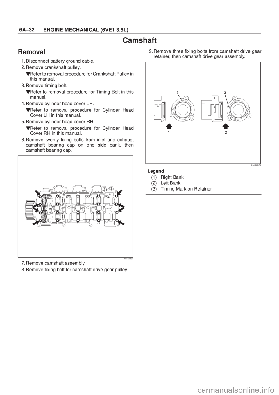
8. Remove fixing bolt for camshaft drive gear pulley.9. Remove three fixing bolts from camshaft drive gear
retainer, then camshaft drive gear assembly.
014RW026
Legend
(1) Right Bank
(2) Left Bank
(3) Timing Mark on Retainer

Cylinder Head Cover LH
Removal
1. Disconnect battery ground cable.
2. Remove engine cover from the dowels on the
common chamber.
F06RY001
3. Disconnect positive cr")

Exhaust Manifold LH
Removal
1. Disconnect battery ground cable.
2. Disconnect O
2 sensor connector.
3. Remove exhaust front pipe three stud nuts from
exhaust side")

Exhaust Manifold RH
Removal
1. Disconnect battery ground cable.
2. Remove torsion bar. Refer to removal procedure in
Front Suspension section.
3. Remove exhaust fr")