Page 934 of 2100
6D1±4
ENGINE ELECTRICAL (6VE1 3.5L)
7. To remove the jumper cables, follow the above
directions in reverse order.
Be sure to first disconnect the negative cable from the
vehicle with the discharged battery.
Battery Removal
061RX002
1. Remove negative cable (1).
2. Remove positive cable (2).
3. Remove retainer screw and rods (3).
4. Remove retainer (4).
5. Remove battery (5).
Battery Installation
1. Install battery (5).
2. Install retainer (4).
3. Install retainer screw and rods (3).
NOTE: Make sure that the rod is hooked on the body
side.
4. Install positive cable (2).
5. Install negative cable (1).
Page 938 of 2100
6D2±3
IGNITION SYSTEM (6VE1 3.5L)
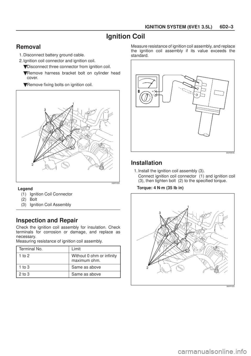
Ignition Coil
Removal
1. Disconnect battery ground cable.
2. Ignition coil connector and ignition coil.
�Disconnect three connector from ignition coil.
�Remove harness bracket bolt on cylinder head
cover.
�Remove fixing bolts on ignition coil.
060RY023
Legend
(1) Ignition Coil Connector
(2) Bolt
(3) Ignition Coil Assembly
Inspection and Repair
Check the ignition coil assembly for insulation. Check
terminals for corrosion or damage, and replace as
necessary.
Measuring resistance of ignition coil assembly.
Terminal No.
Limit
1 to 2Without 0 ohm or infinity
maximum ohm.
1 to 3Same as above
2 to 3Same as above
Measure resistance of ignition coil assembly, and replace
the ignition coil assembly if its value exceeds the
standard.
060RW006
Installation
1. Install the ignition coil assembly (3).
Connect ignition coil connector (1) and ignition coil
(3), then tighten bolt (2) to the specified torque.
Torque: 4 N´m (35 lb in)
060RY023
Page 939 of 2100
6D2±4
IGNITION SYSTEM (6VE1 3.5L)
CAUTION: Ignition coil assembly #6 is different
from ignition coil assembly from #1 to #5. Ignition
coil assembly #6 is short type. So, note it when
installing ignition coil assembly of #6.
060RY00002
Legend
(1) Long type Ignition Coil Assemblies (#1 ~ #5)
(2) Short type Ignition Coil Assembly (#6)
2. Connect battery ground cable.
Page 941 of 2100
6D2±6
IGNITION SYSTEM (6VE1 3.5L)
Crankshaft Position Sensor
Removal
1. Disconnect battery ground cable
2. Wiring connector from crankshaft position sensor.
3. Remove crankshaft position sensor from cylinder
block.
012RS008
Installation
1. Install crankshaft position sensor into the cylinder
block.
Before installation,apply small amount of engine oil to
the O±ring.
Torque: 10 N´m (87 lb in)
2. Reconnect wiring connector to crankshaft position
sensor.
Page 944 of 2100
6D3±2
STARTING AND CHARGING SYSTEM (6VE1 3.5L)
Starting System
General Description
Cranking Circuit
The cranking system consists of a battery, starter, starter
switch, starter relay, etc. These main components are
connected.
Starter
The cranking system employs a magnetic type reduction
starter in which the motor shaft is also used as a pinion
shaft. When the starter switch is turned on, the contacts of
magnetic switch are closed, and the armature rotates. At
the same time, the plunger is attracted, and the pinion is
pushed forward by the shift lever to mesh with the ring
gear.
Then, the ring gear runs to start the engine. When the
engine starts and the starter switch is turned off, the
plunger returns, the pinion is disengaged from the ring
gear, and the armature stops rotation. When the engine
speed is higher than the pinion, the pinion idles, so that
the armature is not driven.
Page 946 of 2100
6D3±4
STARTING AND CHARGING SYSTEM (6VE1 3.5L)
Diagnosis
ConditionPossible causeCorrection
Starter does not runCharging failureRepair charging system
Battery FailureReplace Battery
Terminal connection failureRepair or replace terminal connector
and/or wiring harness
Starter switch failureRepair or replace starter switch
Starter relay failureReplace
Starter failureRepair or replace starter
Page 947 of 2100

Starter
Removal
1. Battery ground cable.
2. Disconnect Heated O
2 Sensor connector (1).
3. Remove exhaust front left pipe(2).
150R100011
4. Disconnect s")
6D3±5
STARTING AND CHARGING SYSTEM (6VE1 3.5L)
Starter
Removal
1. Battery ground cable.
2. Disconnect Heated O
2 Sensor connector (1).
3. Remove exhaust front left pipe(2).
150R100011
4. Disconnect starter wiring connector from terminals
ª30º (1) and ª50º (2).
5. Remove starter assembly mounting bolts on inside
and outside(3).
6. Remove starter assembly (4) toward the bottom of
engine.
065RY00050
Legend
(1) Terminal ª30º
(2) Terminal ª50º
(3) Fixing Bolts
(4) Starter Assembly
Installation
1. Install starter assembly(4).
2. Install mounting bolts and tighten bolts to specified
torque(3).
Torque: 40 N´m (30 lb ft)
3. Reconnect the connectors to terminals ª50º (2)
tighten terminals ª30º (1) to specified torque.
Torque: 9 N´m (78 lb in)
065RY00050
Legend
(1) Terminal ª30º
(2) Terminal ª50º
(3) Fixing Bolts
(4) Starter Assembly
4. Install exhaust front left pipe (2) and tighten bolts and
nuts to specified torque.
Stud Nuts
Torque: 67 N´m (49 lb ft)
Bolts
Torque: 43 N´m (32 lb ft)
Page 948 of 2100
6D3±6
STARTING AND CHARGING SYSTEM (6VE1 3.5L)
5. Connect two Heated O2 Sensor connector (1).
150R100011
6. Reconnect the battery ground cable.

7. To remove the jumper cables, follow the above
directions in reverse order.
Be sure to first disconnect the negative cable from the
vehicle with the discharged b")

CAUTION: Ignition coil assembly #6 is different
from ignition coil assembly from #1 to #5. Ignition
coil assembly #6 is short type. So, note it when
installing ignit")

Crankshaft Position Sensor
Removal
1. Disconnect battery ground cable
2. Wiring connector from crankshaft position sensor.
3. Remove crankshaft position sensor from")

Starting System
General Description
Cranking Circuit
The cranking system consists of a battery, starter, starter
switch, starter relay, etc. These main")

Diagnosis
ConditionPossible causeCorrection
Starter does not runCharging failureRepair charging system
Battery FailureReplace Battery
Terminal connectio")

5. Connect two Heated O2 Sensor connector (1).
150R100011
6. Reconnect the battery ground cable.")