2002 DODGE RAM torque
[x] Cancel search: torquePage 1954 of 2255
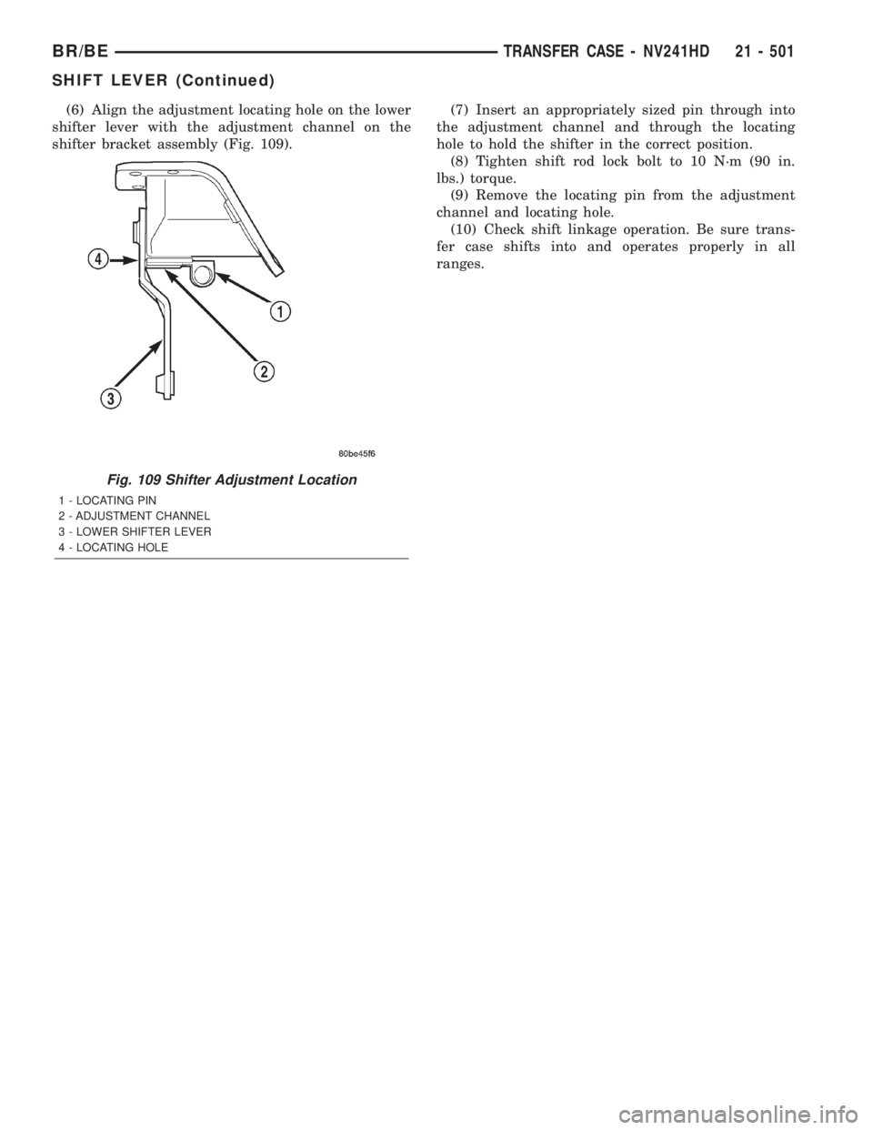
(6) Align the adjustment locating hole on the lower
shifter lever with the adjustment channel on the
shifter bracket assembly (Fig. 109).(7) Insert an appropriately sized pin through into
the adjustment channel and through the locating
hole to hold the shifter in the correct position.
(8) Tighten shift rod lock bolt to 10 N´m (90 in.
lbs.) torque.
(9) Remove the locating pin from the adjustment
channel and locating hole.
(10) Check shift linkage operation. Be sure trans-
fer case shifts into and operates properly in all
ranges.
Fig. 109 Shifter Adjustment Location
1 - LOCATING PIN
2 - ADJUSTMENT CHANNEL
3 - LOWER SHIFTER LEVER
4 - LOCATING HOLE
BR/BETRANSFER CASE - NV241HD 21 - 501
SHIFT LEVER (Continued)
Page 1956 of 2255
TIRES/WHEELS
TABLE OF CONTENTS
page page
TIRES/WHEELS
DIAGNOSIS AND TESTING - TIRE AND
WHEEL RUNOUT......................1
STANDARD PROCEDURE
STANDARD PROCEDURE -
TIRE ROTATION.......................2
STANDARD PROCEDURE - MATCH
MOUNTING...........................3
STANDARD PROCEDURE - TIRE AND
WHEEL BALANCE......................4
TIRES
DESCRIPTION
DESCRIPTION - SPARE TIRE - TEMPORARY...6
DESCRIPTION - TIRES..................6
DESCRIPTION - RADIAL-PLY TIRES........6
DESCRIPTION - TIRE PRESSURE FOR
HIGH SPEEDS.........................7
DESCRIPTION - REPLACEMENT TIRES.....7
DESCRIPTION - TIRE INFLATION
PRESSURES..........................7
DIAGNOSIS AND TESTING
DIAGNOSIS AND TESTING - PRESSURE
GAUGES.............................8
DIAGNOSIS AND TESTING - TREAD WEAR
INDICATORS..........................8
DIAGNOSIS AND TESTING - TIRE WEAR
PATTERNS...........................8DIAGNOSIS AND TESTING - TIRE NOISE
OR VIBRATION........................9
STANDARD PROCEDURE - REPAIRING
LEAKS...............................9
SPECIFICATIONS
TIRE REVOLUTIONS PER MILE...........9
SPARE TIRE
DESCRIPTION.........................10
WHEELS
DESCRIPTION.........................10
OPERATION...........................10
DIAGNOSIS AND TESTING
WHEEL INSPECTION..................11
STANDARD PROCEDURE - DUAL REAR
WHEEL INSTALLATION.................11
SPECIFICATIONS
TORQUE CHART......................11
STUDS
REMOVAL.............................12
INSTALLATION.........................12
WHEEL COVER
REMOVAL.............................12
INSTALLATION
INSTALLATION - REAR.................12
INSTALLATION - FRONT................12
TIRES/WHEELS
DIAGNOSIS AND TESTING - TIRE AND WHEEL
RUNOUT
Radial runout is the difference between the high
and low points on the tire or wheel (Fig. 1).
Lateral runout is thewobbleof the tire or wheel.
Radial runout of more than 1.5 mm (.060 inch)
measured at the center line of the tread may cause
the vehicle to shake.
Lateral runout of more than 2.0 mm (.080 inch)
measured near the shoulder of the tire may cause the
vehicle to shake.
Sometimes radial runout can be reduced. Relocate
the wheel and tire assembly on the mounting studs
(See Method 1). If this does not reduce runout to an
acceptable level, the tire can be rotated on the wheel.
(See Method 2).
Fig. 1 Checking Tire/Wheel/Hub Runout
1 - RADIAL RUNOUT
2 - LATERAL RUNOUT
BR/BETIRES/WHEELS 22 - 1
Page 1957 of 2255
METHOD 1 (RELOCATE WHEEL ON HUB)
(1) Drive vehicle a short distance to eliminate tire
flat spotting from a parked position.
(2) Check wheel bearings and adjust if adjustable
or replace if necessary.
(3) Check the wheel mounting surface.
(4) Relocate wheel on the mounting, two studs
over from the original position.
(5) Tighten wheel nuts until all are properly
torqued, to eliminate brake distortion.
(6) Check radial runout. If still excessive, mark
tire sidewall, wheel, and stud at point of maximum
runout and proceed to Method 2.
METHOD 2 (RELOCATE TIRE ON WHEEL)
NOTE: Rotating the tire on wheel is particularly
effective when there is runout in both tire and
wheel.
(1) Remove tire from wheel and mount wheel on
service dynamic balance machine.
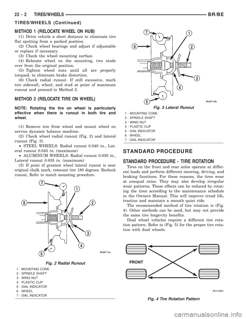
(2) Check wheel radial runout (Fig. 2) and lateral
runout (Fig. 3).
²STEEL WHEELS: Radial runout 0.040 in., Lat-
eral runout 0.045 in. (maximum)
²ALUMINUM WHEELS: Radial runout 0.030 in.,
Lateral runout 0.035 in. (maximum)
(3)
If point of greatest wheel lateral runout is near
original chalk mark, remount tire 180 degrees. Recheck
runout, Refer to match mounting procedure.
STANDARD PROCEDURE
STANDARD PROCEDURE - TIRE ROTATION
Tires on the front and rear axles operate at differ-
ent loads and perform different steering, driving, and
braking functions. For these reasons, the tires wear
at unequal rates. They may also develop irregular
wear patterns. These effects can be reduced by rotat-
ing the tires according to the maintenance schedule
in the Owners Manual. This will improve tread life,
traction and maintain a smooth quiet ride.
The recommended method of tire rotation is (Fig.
4). Other methods can be used, but may not provide
the same tire longevity benefits.
Dual wheel vehicles require a different tire rota-
tion pattern. Refer to (Fig. 5) for the proper tire rota-
tion with dual wheels.
Fig. 2 Radial Runout
1 - MOUNTING CONE
2 - SPINDLE SHAFT
3 - WING NUT
4 - PLASTIC CUP
5 - DIAL INDICATOR
6 - WHEEL
7 - DIAL INDICATOR
Fig. 3 Lateral Runout
1 - MOUNTING CONE
2 - SPINDLE SHAFT
3 - WING NUT
4 - PLASTIC CUP
5 - DIAL INDICATOR
6 - WHEEL
7 - DIAL INDICATOR
Fig. 4 Tire Rotation Pattern
22 - 2 TIRES/WHEELSBR/BE
TIRES/WHEELS (Continued)
Page 1964 of 2255
DIAGNOSIS AND TESTING - TIRE NOISE OR
VIBRATION
Radial-ply tires are sensitive to force impulses
caused by improper mounting, vibration, wheel
defects, or possibly tire imbalance.
To find out if tires are causing the noise or vibra-
tion, drive the vehicle over a smooth road at varying
speeds. Note the noise level during acceleration and
deceleration. The engine, differential and exhaust
noises will change as speed varies, while the tire
noise will usually remain constant.
STANDARD PROCEDURE - REPAIRING LEAKS
For proper repairing, a radial tire must be removed
from the wheel. Repairs should only be made if the
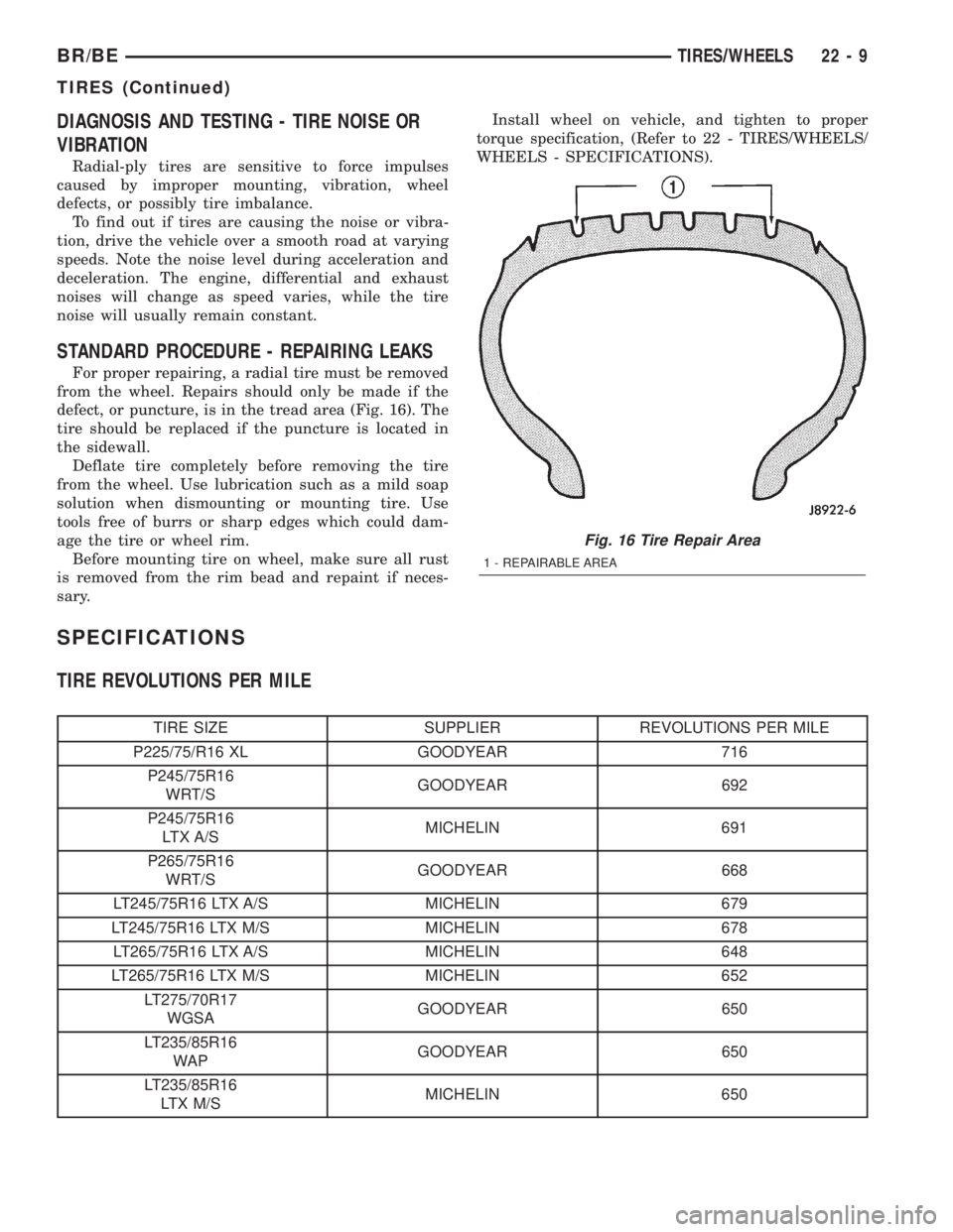
defect, or puncture, is in the tread area (Fig. 16). The
tire should be replaced if the puncture is located in
the sidewall.
Deflate tire completely before removing the tire
from the wheel. Use lubrication such as a mild soap
solution when dismounting or mounting tire. Use
tools free of burrs or sharp edges which could dam-
age the tire or wheel rim.
Before mounting tire on wheel, make sure all rust
is removed from the rim bead and repaint if neces-
sary.Install wheel on vehicle, and tighten to proper
torque specification, (Refer to 22 - TIRES/WHEELS/
WHEELS - SPECIFICATIONS).
SPECIFICATIONS
TIRE REVOLUTIONS PER MILE
TIRE SIZE SUPPLIER REVOLUTIONS PER MILE
P225/75/R16 XL GOODYEAR 716
P245/75R16
WRT/SGOODYEAR 692
P245/75R16
LTX A/SMICHELIN 691
P265/75R16
WRT/SGOODYEAR 668
LT245/75R16 LTX A/S MICHELIN 679
LT245/75R16 LTX M/S MICHELIN 678
LT265/75R16 LTX A/S MICHELIN 648
LT265/75R16 LTX M/S MICHELIN 652
LT275/70R17
WGSAGOODYEAR 650
LT235/85R16
WAPGOODYEAR 650
LT235/85R16
LTX M/SMICHELIN 650
Fig. 16 Tire Repair Area
1 - REPAIRABLE AREA
BR/BETIRES/WHEELS 22 - 9
TIRES (Continued)
Page 1966 of 2255
DIAGNOSIS AND TESTING
WHEEL INSPECTION
Inspect wheels for:
²Excessive run out
²Dents or cracks
²Damaged wheel lug nut holes
²Air Leaks from any area or surface of the rim
NOTE: Do not attempt to repair a wheel by hammer-
ing, heating or welding.
If a wheel is damaged an original equipment
replacement wheel should be used. When obtaining
replacement wheels, they should be equivalent in
load carrying capacity. The diameter, width, offset,
pilot hole and bolt circle of the wheel should be the
same as the original wheel.
WARNING: FAILURE TO USE EQUIVALENT REPLACE-
MENT WHEELS MAY ADVERSELY AFFECT THE
SAFETY AND HANDLING OF THE VEHICLE. USED
WHEELS ARE NOT RECOMMENDED. THE SERVICE
HISTORY OF THE WHEEL MAY HAVE INCLUDED
SEVERE TREATMENT OR VERY HIGH MILEAGE. THE
RIM COULD FAIL WITHOUT WARNING.
STANDARD PROCEDURE - DUAL REAR WHEEL
INSTALLATION
Dual rear wheels use a special heavy duty lug nut
wrench. It is recommended to remove and install dual
rear wheels only when the proper wrench is available.
The wrench is also use to remove wheel center caps for
more information refer to Owner's Manual.
The tires on both wheels must be completely raised
off the ground when tightening the lug nuts. This
will ensure correct wheel centering and maximum
wheel clamping.
A two piece flat face lug nut with right-hand
threads is used for retaining the wheels on the hubs
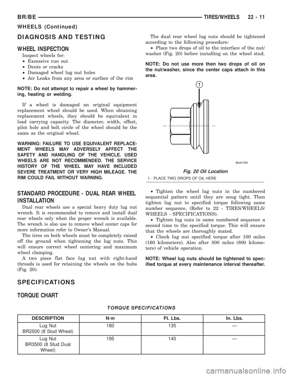
(Fig. 20).The dual rear wheel lug nuts should be tightened
according to the following procedure:
²Place two drops of oil to the interface of the nut/
washer (Fig. 20) before installing on the wheel stud.
NOTE: Do not use more then two drops of oil on
the nut/washer, since the center caps attach in this
area.
²Tighten the wheel lug nuts in the numbered
sequential pattern until they are snug tight. Then
tighten lug nut to specified torque following same
number sequence, (Refer to 22 - TIRES/WHEELS/
WHEELS - SPECIFICATIONS).
²Tighten lug nuts in same numbered sequence a
second time to the specified torque. This will ensure
that the wheels are thoroughly mated.
²Check lug nut specified torque after 100 miles
(160 kilometers). Also after 500 miles (800 kilome-
ters) of vehicle operation.
NOTE: Wheel lug nuts should be tightened to spec-
ified torque at every maintenance interval thereafter.
SPECIFICATIONS
TORQUE CHART
TORQUE SPECIFICATIONS
DESCRIPTION N´m Ft. Lbs. In. Lbs.
Lug Nut
BR2500 (8 Stud Wheel)180 135 Ð
Lug Nut
BR3500 (8 Stud Dual
Wheel)195 145 Ð
Fig. 20 Oil Location
1 - PLACE TWO DROPS OF OIL HERE
BR/BETIRES/WHEELS 22 - 11
WHEELS (Continued)
Page 1968 of 2255
BODY
TABLE OF CONTENTS
page page
BODY
WARNING
SAFETY PRECAUTIONS AND WARNINGS . . . 1
DIAGNOSIS AND TESTING
DIAGNOSIS AND TESTING - WATER LEAKS . 2
DIAGNOSIS AND TESTING - WIND NOISE . . . 3
SPECIFICATIONS
WELD LOCATIONS.....................4
STRUCTURAL ADHESIVE LOCATIONS.....44
BODY SEALER LOCATIONS.............47
BODY GAP AND FLUSH MEASUREMENTS . . 56
BODY OPENING DIMENSIONS...........60TORQUE SPECIFICATIONS.............61
DECKLID/HATCH/LIFTGATE/TAILGATE.......63
DOOR - FRONT.........................68
DOOR - CARGO.........................77
EXTERIOR.............................86
HOOD................................100
INSTRUMENT PANEL SYSTEM............105
INTERIOR.............................118
PAINT................................129
SEATS...............................131
STATIONARY GLASS....................145
WEATHERSTRIP/SEALS..................151
BODY
WARNING
SAFETY PRECAUTIONS AND WARNINGS
WARNING: USE AN OSHA APPROVED BREATHING
FILTER WHEN SPRAYING PAINT OR SOLVENTS IN
A CONFINED AREA. PERSONAL INJURY CAN
RESULT.
²AVOID PROLONGED SKIN CONTACT WITH
PETROLEUM OR ALCOHOL ± BASED CLEANING
SOLVENTS. PERSONAL INJURY CAN RESULT.
²DO NOT STAND UNDER A HOISTED VEHICLE
THAT IS NOT PROPERLY SUPPORTED ON SAFETY
STANDS. PERSONAL INJURY CAN RESULT.CAUTION: When holes must be drilled or punched
in an inner body panel, verify depth of space to the
outer body panel, electrical wiring, or other compo-
nents. Damage to vehicle can result.
²Do not weld exterior panels unless combustible
material on the interior of vehicle is removed from
the repair area. Fire or hazardous conditions, can
result.
²Always have a fire extinguisher ready for use
when welding.
²Disconnect the negative (-) cable clamp from
the battery when servicing electrical components
that are live when the ignition is OFF. Damage to
electrical system can result.
²Do not use abrasive chemicals or compounds
on painted surfaces. Damage to finish can result.
²Do not use harsh alkaline based cleaning sol-
vents on painted or upholstered surfaces. Damage
to finish or color can result.
²Do not hammer or pound on plastic trim panel
when servicing interior trim. Plastic panels can
break.
BR/BEBODY 23 - 1
Page 2028 of 2255
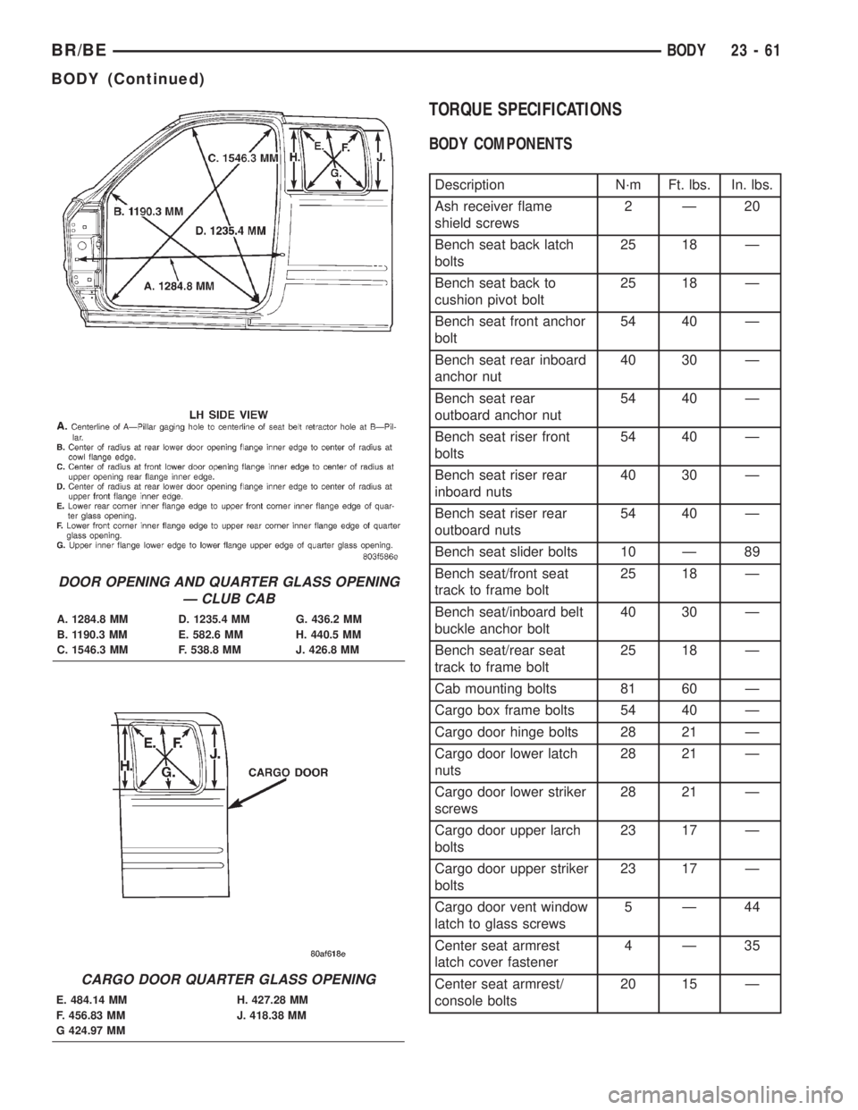
TORQUE SPECIFICATIONS
BODY COMPONENTS
Description N´m Ft. lbs. In. lbs.
Ash receiver flame
shield screws2Ð20
Bench seat back latch
bolts25 18 Ð
Bench seat back to
cushion pivot bolt25 18 Ð
Bench seat front anchor
bolt54 40 Ð
Bench seat rear inboard
anchor nut40 30 Ð
Bench seat rear
outboard anchor nut54 40 Ð
Bench seat riser front
bolts54 40 Ð
Bench seat riser rear
inboard nuts40 30 Ð
Bench seat riser rear
outboard nuts54 40 Ð
Bench seat slider bolts 10 Ð 89
Bench seat/front seat
track to frame bolt25 18 Ð
Bench seat/inboard belt
buckle anchor bolt40 30 Ð
Bench seat/rear seat
track to frame bolt25 18 Ð
Cab mounting bolts 81 60 Ð
Cargo box frame bolts 54 40 Ð
Cargo door hinge bolts 28 21 Ð
Cargo door lower latch
nuts28 21 Ð
Cargo door lower striker
screws28 21 Ð
Cargo door upper larch
bolts23 17 Ð
Cargo door upper striker
bolts23 17 Ð
Cargo door vent window
latch to glass screws5Ð44
Center seat armrest
latch cover fastener4Ð35
Center seat armrest/
console bolts20 15 Ð
DOOR OPENING AND QUARTER GLASS OPENING
Ð CLUB CAB
A. 1284.8 MM D. 1235.4 MM G. 436.2 MM
B. 1190.3 MM E. 582.6 MM H. 440.5 MM
C. 1546.3 MM F. 538.8 MM J. 426.8 MM
CARGO DOOR QUARTER GLASS OPENING
E. 484.14 MM H. 427.28 MM
F. 456.83 MM J. 418.38 MM
G 424.97 MM
BR/BEBODY 23 - 61
BODY (Continued)
Page 2036 of 2255
(14) Inspect for air bubbles. Small bubbles can be
pierced with a sharp pin and smoothed out.
(15) Install outer belt weatherstrip (Refer to 23 -
BODY/WEATHERSTRIP/SEALS/FDR OUTER BELT
WEATHERSTRIP - INSTALLATION).
(16) Install glass run weatherstrip (Refer to 23 -
BODY/WEATHERSTRIP/SEALS/FDR GLASS RUN
WEATHERSTRIP - INSTALLATION).
DOOR
REMOVAL
(1) Remove cowl trim panel (Refer to 23 - BODY/
INTERIOR/COWL TRIM COVER - REMOVAL).
(2) Disengage door wire harness connector of
instrument panel harness and push door harness
through access hole in pillar.
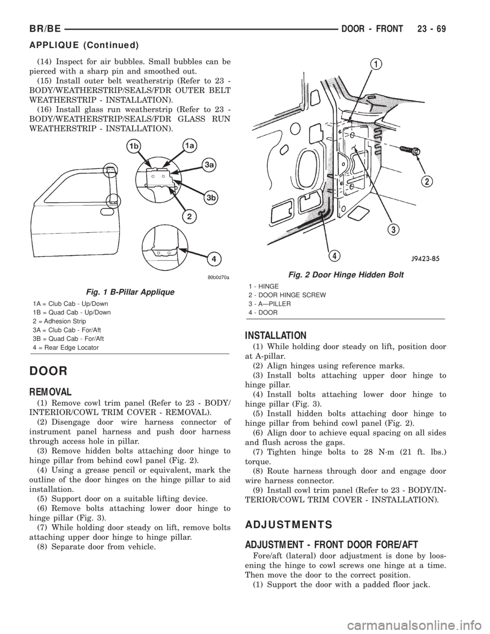
(3) Remove hidden bolts attaching door hinge to
hinge pillar from behind cowl panel (Fig. 2).
(4) Using a grease pencil or equivalent, mark the
outline of the door hinges on the hinge pillar to aid
installation.
(5) Support door on a suitable lifting device.
(6) Remove bolts attaching lower door hinge to
hinge pillar (Fig. 3).
(7) While holding door steady on lift, remove bolts
attaching upper door hinge to hinge pillar.
(8) Separate door from vehicle.
INSTALLATION
(1) While holding door steady on lift, position door
at A-pillar.
(2) Align hinges using reference marks.
(3) Install bolts attaching upper door hinge to
hinge pillar.
(4) Install bolts attaching lower door hinge to
hinge pillar (Fig. 3).
(5) Install hidden bolts attaching door hinge to
hinge pillar from behind cowl panel (Fig. 2).
(6) Align door to achieve equal spacing on all sides
and flush across the gaps.
(7) Tighten hinge bolts to 28 N´m (21 ft. lbs.)
torque.
(8) Route harness through door and engage door
wire harness connector.
(9) Install cowl trim panel (Refer to 23 - BODY/IN-
TERIOR/COWL TRIM COVER - INSTALLATION).
ADJUSTMENTS
ADJUSTMENT - FRONT DOOR FORE/AFT
Fore/aft (lateral) door adjustment is done by loos-
ening the hinge to cowl screws one hinge at a time.
Then move the door to the correct position.
(1) Support the door with a padded floor jack.
Fig. 1 B-Pillar Applique
1A = Club Cab - Up/Down
1B = Quad Cab - Up/Down
2 = Adhesion Strip
3A = Club Cab - For/Aft
3B = Quad Cab - For/Aft
4 = Rear Edge Locator
Fig. 2 Door Hinge Hidden Bolt
1 - HINGE
2 - DOOR HINGE SCREW
3 - AÐPILLER
4 - DOOR
BR/BEDOOR - FRONT 23 - 69
APPLIQUE (Continued)