Page 1901 of 2255
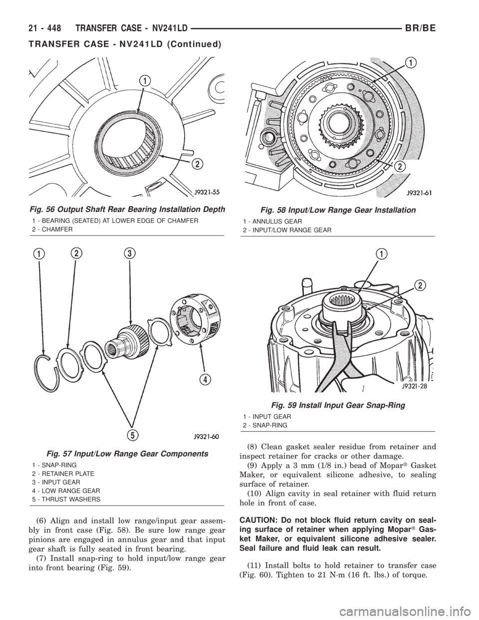
(6) Align and install low range/input gear assem-
bly in front case (Fig. 58). Be sure low range gear
pinions are engaged in annulus gear and that input
gear shaft is fully seated in front bearing.
(7) Install snap-ring to hold input/low range gear
into front bearing (Fig. 59).(8) Clean gasket sealer residue from retainer and
inspect retainer for cracks or other damage.
(9) Applya3mm(1/8 in.) bead of MopartGasket
Maker, or equivalent silicone adhesive, to sealing
surface of retainer.
(10) Align cavity in seal retainer with fluid return
hole in front of case.
CAUTION: Do not block fluid return cavity on seal-
ing surface of retainer when applying MoparTGas-
ket Maker, or equivalent silicone adhesive sealer.
Seal failure and fluid leak can result.
(11) Install bolts to hold retainer to transfer case
(Fig. 60). Tighten to 21 N´m (16 ft. lbs.) of torque.
Fig. 56 Output Shaft Rear Bearing Installation Depth
1 - BEARING (SEATED) AT LOWER EDGE OF CHAMFER
2 - CHAMFER
Fig. 57 Input/Low Range Gear Components
1 - SNAP-RING
2 - RETAINER PLATE
3 - INPUT GEAR
4 - LOW RANGE GEAR
5 - THRUST WASHERS
Fig. 58 Input/Low Range Gear Installation
1 - ANNULUS GEAR
2 - INPUT/LOW RANGE GEAR
Fig. 59 Install Input Gear Snap-Ring
1 - INPUT GEAR
2 - SNAP-RING
21 - 448 TRANSFER CASE - NV241LDBR/BE
TRANSFER CASE - NV241LD (Continued)
Page 1905 of 2255
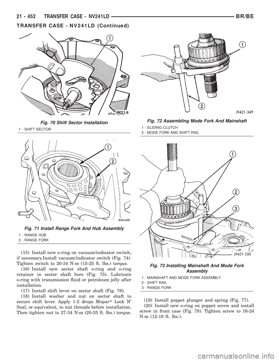
(15) Install new o-ring on vacuum/indicator switch,
if necessary.Install vacuum/indicator switch (Fig. 74).
Tighten switch to 20-34 N´m (15-25 ft. lbs.) torque.
(16) Install new sector shaft o-ring and o-ring
retainer in sector shaft bore (Fig. 75). Lubricate
o-ring with transmission fluid or petroleum jelly after
installation.
(17) Install shift lever on sector shaft (Fig. 76).
(18) Install washer and nut on sector shaft to
secure shift lever. Apply 1-2 drops MopartLock N'
Seal, or equivalent, to nut threads before installation.
Then tighten nut to 27-34 N´m (20-25 ft. lbs.) torque.(19) Install poppet plunger and spring (Fig. 77).
(20) Install new o-ring on poppet screw and install
screw in front case (Fig. 78). Tighten screw to 16-24
N´m (12-18 ft. lbs.).
Fig. 70 Shift Sector Installation
1 - SHIFT SECTOR
Fig. 71 Install Range Fork And Hub Assembly
1 - RANGE HUB
2 - RANGE FORK
Fig. 72 Assembling Mode Fork And Mainshaft
1 - SLIDING CLUTCH
2 - MODE FORK AND SHIFT RAIL
Fig. 73 Installing Mainshaft And Mode Fork
Assembly
1 - MAINSHAFT AND MODE FORK ASSEMBLY
2 - SHIFT RAIL
3 - RANGE FORK
21 - 452 TRANSFER CASE - NV241LDBR/BE
TRANSFER CASE - NV241LD (Continued)
Page 1908 of 2255

(3) Insert oil pickup tube in oil pump and position
pump in rear case (Fig. 86).(4) Apply bead of MopartGasket Maker, or equiv-
alent, to mating surface of front case. Keep sealer
bead width to maximum of 3/16 inch. Do not use
excessive amount of sealer as excess will be displaced
into case interior.
(5) Align oil pump with mainshaft and align shift
rail with bore in rear case. Then install rear case and
oil pump assembly (Fig. 87). Be sure oil pump and
pickup tube remain in position during case installa-
tion.
(6) Install 4-5 rear case-to front case bolts to hold
rear case in position. Tighten bolts snug but not to
specified torque at this time.
CAUTION: Verify that shift rail (Fig. 88), and case
alignment dowels are seated before installing any
bolts. Case could be cracked if shaft rail or dowels
are misaligned.
(7) Verify that oil pump is aligned and seated on
rear case. Reposition pump if necessary.
(8) Check stud at end of case halves (Fig. 89). If
stud was loosened or came out during disassembly,
apply LoctiteŸ 242 to stud threads and reseat stud
in case.
(9) Apply LoctiteŸ 242 to remainder of rear case-
to-front case bolt threads and install bolts. Be sure
lock washers are used on studs/bolts at case ends.
Tighten bolts, or stud nuts as follows:
Fig. 83 Case Magnet Installation
1 - MAGNET
2 - CASE POCKET
Fig. 84 Pickup Tube O-Ring Installation
1 - O-RING (PUMP PICKUP)
2 - PICKUP TUBE
Fig. 85 Oil Pickup Tube And Filter Position In Rear
Case
1 - FILTER
2 - TUBE AND HOSE
3 - TUBE IN NOTCH
Fig. 86 Positioning Oil Pump In Rear Case
1 - OIL PUMP
2 - REAR CASE
3 - FILTER
4 - PICKUP TUBE
BR/BETRANSFER CASE - NV241LD 21 - 455
TRANSFER CASE - NV241LD (Continued)
Page 1909 of 2255
²flange head bolts to 47-61 N´m (35-45 ft. lbs.)
²all other bolts/nuts to 27-34 N´m (20-25 ft. lbs.)
(10) Install rear output bearing and snap-ring to
output shaft.
COMPANION FLANGE
(1) Install companion flange seal on front shaft
(Fig. 90).
(2) Install companion flange on front shaft (Fig.
91). Then install and tighten flange nut to 176-271
N´m (130-200 ft. lbs.) torque.
Fig. 87 Rear Case And Oil Pump Installation
1 - MAINSHAFT
2 - OIL PUMP
3 - REAR CASE
Fig. 88 Shift Rail Seated In Rear Case Bore
1 - REAR CASE
2 - SHIFT RAIL
Fig. 89 Washer Installation On Case Stud And
Dowel Bolts
1 - CASE STUD/BOLT
2 - WASHER
Fig. 90 Installing Flange Seal On Front Shaft
1 - FRONT OUTPUT SHAFT
2 - FLANGE SEAL
Fig. 91 Installing Companion Flange On Front Shaft
1 - COMPANION FLANGE
21 - 456 TRANSFER CASE - NV241LDBR/BE
TRANSFER CASE - NV241LD (Continued)
Page 1910 of 2255
REAR RETAINER AND EXTENSION
(1) Clean mating surfaces of transfer case housing
and the rear retainer of any original gasket material.
(2) Install new rear retainer gasket onto the trans-
fer case housing or rear retainer.
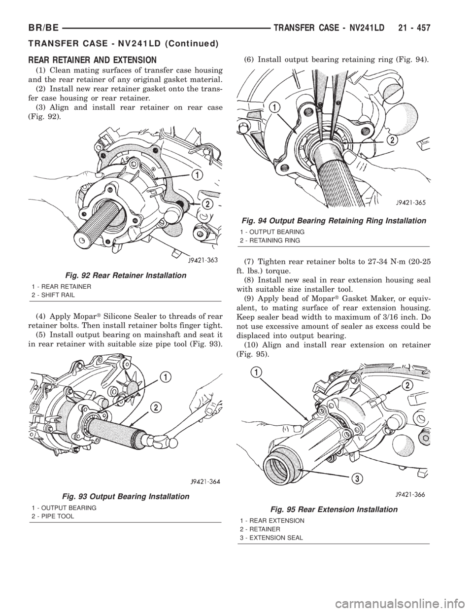
(3) Align and install rear retainer on rear case
(Fig. 92).
(4) Apply MopartSilicone Sealer to threads of rear
retainer bolts. Then install retainer bolts finger tight.
(5) Install output bearing on mainshaft and seat it
in rear retainer with suitable size pipe tool (Fig. 93).(6) Install output bearing retaining ring (Fig. 94).
(7) Tighten rear retainer bolts to 27-34 N´m (20-25
ft. lbs.) torque.
(8) Install new seal in rear extension housing seal
with suitable size installer tool.
(9) Apply bead of MopartGasket Maker, or equiv-
alent, to mating surface of rear extension housing.
Keep sealer bead width to maximum of 3/16 inch. Do
not use excessive amount of sealer as excess could be
displaced into output bearing.
(10) Align and install rear extension on retainer
(Fig. 95).
Fig. 92 Rear Retainer Installation
1 - REAR RETAINER
2 - SHIFT RAIL
Fig. 93 Output Bearing Installation
1 - OUTPUT BEARING
2 - PIPE TOOL
Fig. 94 Output Bearing Retaining Ring Installation
1 - OUTPUT BEARING
2 - RETAINING RING
Fig. 95 Rear Extension Installation
1 - REAR EXTENSION
2 - RETAINER
3 - EXTENSION SEAL
BR/BETRANSFER CASE - NV241LD 21 - 457
TRANSFER CASE - NV241LD (Continued)
Page 1911 of 2255
(11) Apply MopartSilicone Sealer to threads of
rear extension housing bolts. Then install and
tighten bolts to 27-34 N´m (20-25 ft. lbs.) torque.
INSTALLATION
(1) Align and seat transfer case on transmission.
Be sure transfer case input gear splines are aligned
with transmission output shaft. Align splines by
rotating transfer case rear output shaft yoke if nec-
essary. Do not install any transfer case attaching
nuts until the transfer case is completely seated
against the transmission.
(2) Install and tighten transfer case attaching
nuts. Tighten nuts to 30-41 N´m (20-30 ft.lbs.).
(3) Install rear crossmember.(4) Remove jack stand from under transmission.
(5) Align and connect propeller shafts. (Refer to 3 -
DIFFERENTIAL & DRIVELINE/PROPELLER
SHAFT/PROPELLER SHAFT - INSTALLATION)
(6) Connect vacuum harness and vent hose.
(7) Connect shift rod to transfer case lever or floor
shift arm. Use channel lock style pliers to press rod
back into lever grommet.
(8) Adjust shift linkage, if necessary.
(9) Fill transfer case with recommended transmis-
sion fluid and install fill plug.
(10) Install skid plate, if equipped. (Refer to 13 -
FRAMES & BUMPERS/FRAME/TRANSFER CASE
SKID PLATE - INSTALLATION)
(11) Lower vehicle
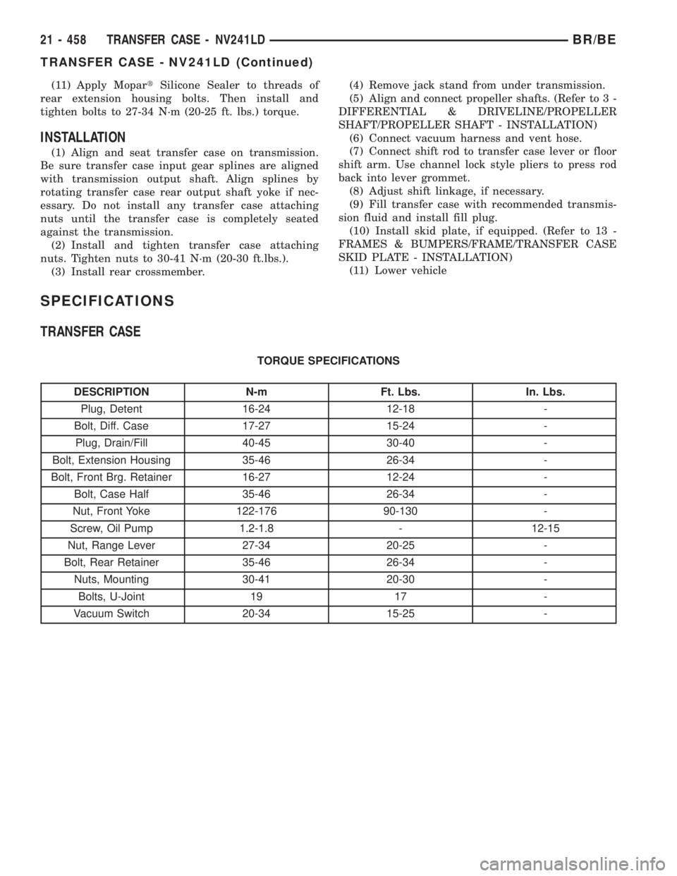
SPECIFICATIONS
TRANSFER CASE
TORQUE SPECIFICATIONS
DESCRIPTION N-m Ft. Lbs. In. Lbs.
Plug, Detent 16-24 12-18 -
Bolt, Diff. Case 17-27 15-24 -
Plug, Drain/Fill 40-45 30-40 -
Bolt, Extension Housing 35-46 26-34 -
Bolt, Front Brg. Retainer 16-27 12-24 -
Bolt, Case Half 35-46 26-34 -
Nut, Front Yoke 122-176 90-130 -
Screw, Oil Pump 1.2-1.8 - 12-15
Nut, Range Lever 27-34 20-25 -
Bolt, Rear Retainer 35-46 26-34 -
Nuts, Mounting 30-41 20-30 -
Bolts, U-Joint 19 17 -
Vacuum Switch 20-34 15-25 -
21 - 458 TRANSFER CASE - NV241LDBR/BE
TRANSFER CASE - NV241LD (Continued)
Page 1915 of 2255
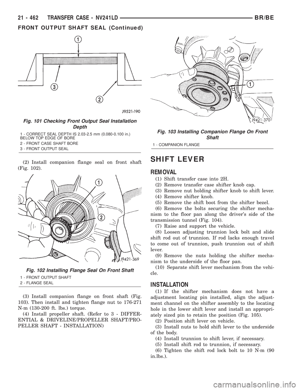
(2) Install companion flange seal on front shaft
(Fig. 102).
(3) Install companion flange on front shaft (Fig.
103). Then install and tighten flange nut to 176-271
N´m (130-200 ft. lbs.) torque.
(4) Install propeller shaft. (Refer to 3 - DIFFER-
ENTIAL & DRIVELINE/PROPELLER SHAFT/PRO-
PELLER SHAFT - INSTALLATION)SHIFT LEVER
REMOVAL
(1) Shift transfer case into 2H.
(2) Remove transfer case shifter knob cap.
(3) Remove nut holding shifter knob to shift lever.
(4) Remove shifter knob.
(5) Remove the shift boot from the shifter bezel.
(6) Remove the bolts securing the shifter mecha-
nism to the floor pan along the driver's side of the
transmission tunnel (Fig. 104).
(7) Raise and support the vehicle.
(8) Loosen adjusting trunnion lock bolt and slide
shift rod out of trunnion. If rod lacks enough travel
to come out of trunnion, push trunnion out of shift
lever.
(9) Remove the nuts holding the shifter mecha-
nism to the underside of the floor pan.
(10) Separate shift lever mechanism from the vehi-
cle.
INSTALLATION
(1) If the shifter mechanism does not have a
adjustment locating pin installed, align the adjust-
ment channel on the shifter assembly to the locating
hole in the lower shift lever and install an appropri-
ately sized pin to retain the position (Fig. 105).
(2) Position shift lever on vehicle.
(3) Install nuts to hold shift lever to the underside
of the body.
(4) Install trunnion to shift lever, if necessary.
(5) Install shift rod to trunnion, if necessary.
(6) Tighten the shift rod lock bolt to 10 N´m (90
in.lbs.).
Fig. 101 Checking Front Output Seal Installation
Depth
1 - CORRECT SEAL DEPTH IS 2.03-2.5 mm (0.080-0.100 in.)
BELOW TOP EDGE OF BORE
2 - FRONT CASE SHAFT BORE
3 - FRONT OUTPUT SEAL
Fig. 102 Installing Flange Seal On Front Shaft
1 - FRONT OUTPUT SHAFT
2 - FLANGE SEAL
Fig. 103 Installing Companion Flange On Front
Shaft
1 - COMPANION FLANGE
21 - 462 TRANSFER CASE - NV241LDBR/BE
FRONT OUTPUT SHAFT SEAL (Continued)
Page 1917 of 2255
(5) Verify that transfer case shift lever is in 2H
detent position. The 2H detent position on the trans-
fer case shift arm is the second position from full for-
ward.
(6) Align the adjustment locating hole on the lower
shifter lever with the adjustment channel on the
shifter bracket assembly (Fig. 107).
(7) Insert an appropriately sized pin through into
the adjustment channel and through the locating
hole to hold the shifter in the correct position.
(8) Tighten shift rod lock bolt to 10 N´m (90 in.
lbs.) torque.
(9) Remove the locating pin from the adjustment
channel and locating hole.
(10) Check shift linkage operation. Be sure trans-
fer case shifts into and operates properly in all
ranges.
Fig. 107 Shifter Adjustment Location
1 - LOCATING PIN
2 - ADJUSTMENT CHANNEL
3 - LOWER SHIFTER LEVER
4 - LOCATING HOLE
21 - 464 TRANSFER CASE - NV241LDBR/BE
SHIFT LEVER (Continued)