2002 DODGE RAM torque
[x] Cancel search: torquePage 1918 of 2255
TRANSFER CASE - NV241HD
TABLE OF CONTENTS
page page
TRANSFER CASE - NV241HD
DESCRIPTION........................465
OPERATION..........................467
DIAGNOSIS AND TESTING - TRANSFER
CASE..............................467
REMOVAL............................469
DISASSEMBLY........................469
CLEANING...........................476
INSPECTION.........................476
ASSEMBLY...........................480
INSTALLATION........................494
SPECIFICATIONS
TRANSFER CASE....................495
SPECIAL TOOLS
TRANSFER CASE - NV241HD...........495EXTENSION HOUSING BUSHING AND SEAL
REMOVAL............................497
INSTALLATION........................497
FLUID
STANDARD PROCEDURE - FLUID DRAIN/
REFILL............................497
FRONT OUTPUT SHAFT SEAL
REMOVAL............................498
INSTALLATION........................498
SHIFT LEVER
REMOVAL............................499
INSTALLATION........................500
ADJUSTMENTS
ADJUSTMENT - SHIFT LEVER..........500
TRANSFER CASE - NV241HD
DESCRIPTION
The NV241HD is a part-time transfer case with a
low-range gear system. The transfer case provides
three operating ranges plus a NEUTRAL position.
The low range position provides a gear reduction
ratio of 2.72:1 for increased low speed torque capabil-
ity. Operating ranges are: 2H, 4H, and 4LO.
The synchronizer mechanism consists of a brass
stop ring, synchronizer hub, and the sliding clutch
(Fig. 1). The synchronizer components allow the
transfer case to be shifted between the 2H and 4H
operating ranges while the vehicle is in motion.The gear cases, retainer and extension are all of
aluminum. Drive sprockets and an interconnecting
drive chain are used to transmit engine torque to the
front/rear propeller shafts. The mainshaft, input gear
and front output shaft are supported by ball and nee-
dle bearings.
PTO CAPABILITY
The NV241HD transfer case has power take-off
capability. A PTO gear permanently attached to the
planetary carrier, and a removable PTO cover are
provided for this purpose.
BR/BETRANSFER CASE - NV241HD 21 - 465
Page 1921 of 2255
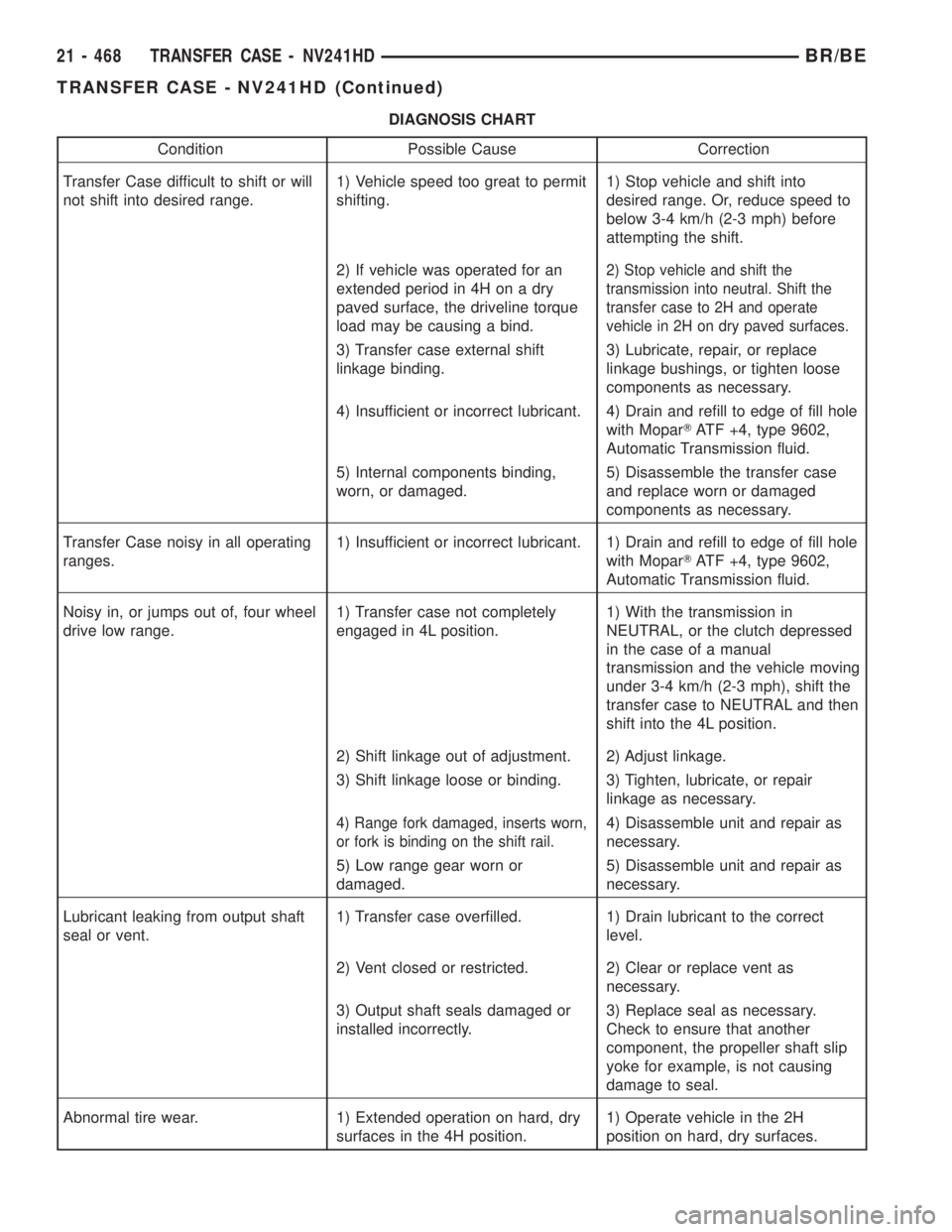
DIAGNOSIS CHART
Condition Possible Cause Correction
Transfer Case difficult to shift or will
not shift into desired range.1) Vehicle speed too great to permit
shifting.1) Stop vehicle and shift into
desired range. Or, reduce speed to
below 3-4 km/h (2-3 mph) before
attempting the shift.
2) If vehicle was operated for an
extended period in 4H on a dry
paved surface, the driveline torque
load may be causing a bind.
2) Stop vehicle and shift the
transmission into neutral. Shift the
transfer case to 2H and operate
vehicle in 2H on dry paved surfaces.
3) Transfer case external shift
linkage binding.3) Lubricate, repair, or replace
linkage bushings, or tighten loose
components as necessary.
4) Insufficient or incorrect lubricant. 4) Drain and refill to edge of fill hole
with MoparTATF +4, type 9602,
Automatic Transmission fluid.
5) Internal components binding,
worn, or damaged.5) Disassemble the transfer case
and replace worn or damaged
components as necessary.
Transfer Case noisy in all operating
ranges.1) Insufficient or incorrect lubricant. 1) Drain and refill to edge of fill hole
with MoparTATF +4, type 9602,
Automatic Transmission fluid.
Noisy in, or jumps out of, four wheel
drive low range.1) Transfer case not completely
engaged in 4L position.1) With the transmission in
NEUTRAL, or the clutch depressed
in the case of a manual
transmission and the vehicle moving
under 3-4 km/h (2-3 mph), shift the
transfer case to NEUTRAL and then
shift into the 4L position.
2) Shift linkage out of adjustment. 2) Adjust linkage.
3) Shift linkage loose or binding. 3) Tighten, lubricate, or repair
linkage as necessary.
4) Range fork damaged, inserts worn,
or fork is binding on the shift rail.4) Disassemble unit and repair as
necessary.
5) Low range gear worn or
damaged.5) Disassemble unit and repair as
necessary.
Lubricant leaking from output shaft
seal or vent.1) Transfer case overfilled. 1) Drain lubricant to the correct
level.
2) Vent closed or restricted. 2) Clear or replace vent as
necessary.
3) Output shaft seals damaged or
installed incorrectly.3) Replace seal as necessary.
Check to ensure that another
component, the propeller shaft slip
yoke for example, is not causing
damage to seal.
Abnormal tire wear. 1) Extended operation on hard, dry
surfaces in the 4H position.1) Operate vehicle in the 2H
position on hard, dry surfaces.
21 - 468 TRANSFER CASE - NV241HDBR/BE
TRANSFER CASE - NV241HD (Continued)
Page 1938 of 2255
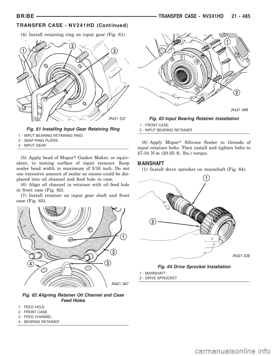
(4) Install retaining ring on input gear (Fig. 61).
(5) Apply bead of MopartGasket Maker, or equiv-
alent, to mating surface of input retainer. Keep
sealer bead width to maximum of 3/16 inch. Do not
use excessive amount of sealer as excess could be dis-
placed into oil channel and feed hole in case.
(6) Align oil channel in retainer with oil feed hole
in front case (Fig. 62).
(7) Install retainer on input gear shaft and front
case (Fig. 63).(8) Apply MopartSilicone Sealer to threads of
input retainer bolts. Then install and tighten bolts to
27-34 N´m (20-25 ft. lbs.) torque.
MAINSHAFT
(1) Install drive sprocket on mainshaft (Fig. 64).
Fig. 61 Installing Input Gear Retaining Ring
1 - INPUT BEARING RETAINING RING
2 - SNAP-RING PLIERS
3 - INPUT GEAR
Fig. 62 Aligning Retainer Oil Channel and Case
Feed Holes
1 - FEED HOLE
2 - FRONT CASE
3 - FEED CHANNEL
4 - BEARING RETAINER
Fig. 63 Input Bearing Retainer Installation
1 - FRONT CASE
2 - INPUT BEARING RETAINER
Fig. 64 Drive Sprocket Installation
1 - MAINSHAFT
2 - DRIVE SPROCKET
BR/BETRANSFER CASE - NV241HD 21 - 485
TRANSFER CASE - NV241HD (Continued)
Page 1943 of 2255
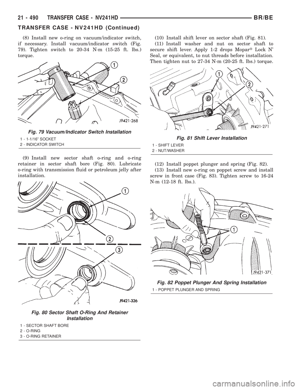
(8) Install new o-ring on vacuum/indicator switch,
if necessary. Install vacuum/indicator switch (Fig.
79). Tighten switch to 20-34 N´m (15-25 ft. lbs.)
torque.
(9) Install new sector shaft o-ring and o-ring
retainer in sector shaft bore (Fig. 80). Lubricate
o-ring with transmission fluid or petroleum jelly after
installation.(10) Install shift lever on sector shaft (Fig. 81).
(11) Install washer and nut on sector shaft to
secure shift lever. Apply 1-2 drops MopartLock N'
Seal, or equivalent, to nut threads before installation.
Then tighten nut to 27-34 N´m (20-25 ft. lbs.) torque.
(12) Install poppet plunger and spring (Fig. 82).
(13) Install new o-ring on poppet screw and install
screw in front case (Fig. 83). Tighten screw to 16-24
N´m (12-18 ft. lbs.).
Fig. 79 Vacuum/Indicator Switch Installation
1 - 1-1/16º SOCKET
2 - INDICATOR SWITCH
Fig. 80 Sector Shaft O-Ring And Retainer
Installation
1 - SECTOR SHAFT BORE
2 - O-RING
3 - O-RING RETAINER
Fig. 81 Shift Lever Installation
1 - SHIFT LEVER
2 - NUT/WASHER
Fig. 82 Poppet Plunger And Spring Installation
1 - POPPET PLUNGER AND SPRING
21 - 490 TRANSFER CASE - NV241HDBR/BE
TRANSFER CASE - NV241HD (Continued)
Page 1945 of 2255
(7) Realign sliding clutch on synchronizer hub if
necessary. Press synchronizer struts inward to ease
realignment. Be sure mainshaft is fully seated before
proceeding.
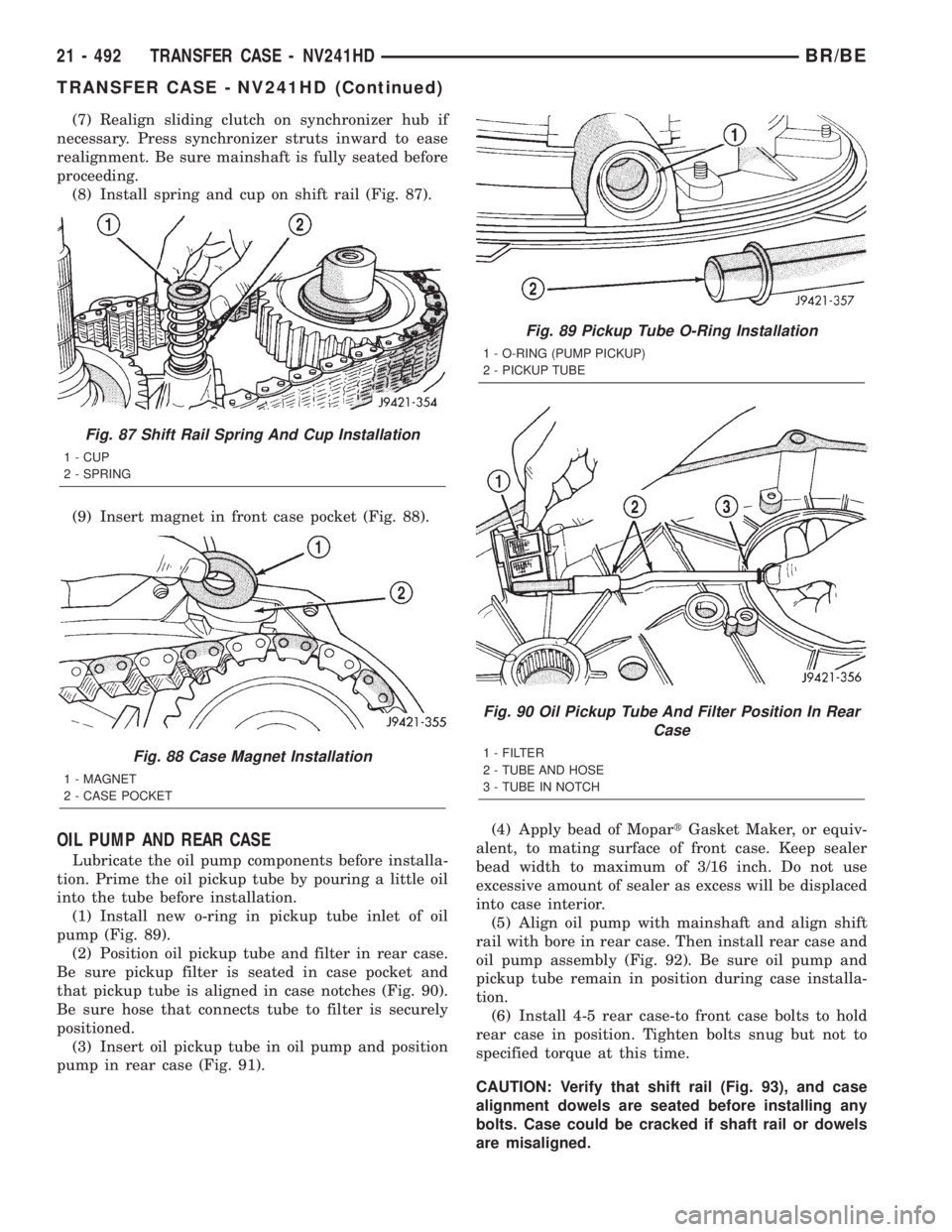
(8) Install spring and cup on shift rail (Fig. 87).
(9) Insert magnet in front case pocket (Fig. 88).
OIL PUMP AND REAR CASE
Lubricate the oil pump components before installa-
tion. Prime the oil pickup tube by pouring a little oil
into the tube before installation.
(1) Install new o-ring in pickup tube inlet of oil
pump (Fig. 89).
(2) Position oil pickup tube and filter in rear case.
Be sure pickup filter is seated in case pocket and
that pickup tube is aligned in case notches (Fig. 90).
Be sure hose that connects tube to filter is securely
positioned.
(3) Insert oil pickup tube in oil pump and position
pump in rear case (Fig. 91).(4) Apply bead of MopartGasket Maker, or equiv-
alent, to mating surface of front case. Keep sealer
bead width to maximum of 3/16 inch. Do not use
excessive amount of sealer as excess will be displaced
into case interior.
(5) Align oil pump with mainshaft and align shift
rail with bore in rear case. Then install rear case and
oil pump assembly (Fig. 92). Be sure oil pump and
pickup tube remain in position during case installa-
tion.
(6) Install 4-5 rear case-to front case bolts to hold
rear case in position. Tighten bolts snug but not to
specified torque at this time.
CAUTION: Verify that shift rail (Fig. 93), and case
alignment dowels are seated before installing any
bolts. Case could be cracked if shaft rail or dowels
are misaligned.
Fig. 87 Shift Rail Spring And Cup Installation
1 - CUP
2 - SPRING
Fig. 88 Case Magnet Installation
1 - MAGNET
2 - CASE POCKET
Fig. 89 Pickup Tube O-Ring Installation
1 - O-RING (PUMP PICKUP)
2 - PICKUP TUBE
Fig. 90 Oil Pickup Tube And Filter Position In Rear
Case
1 - FILTER
2 - TUBE AND HOSE
3 - TUBE IN NOTCH
21 - 492 TRANSFER CASE - NV241HDBR/BE
TRANSFER CASE - NV241HD (Continued)
Page 1947 of 2255
COMPANION FLANGE
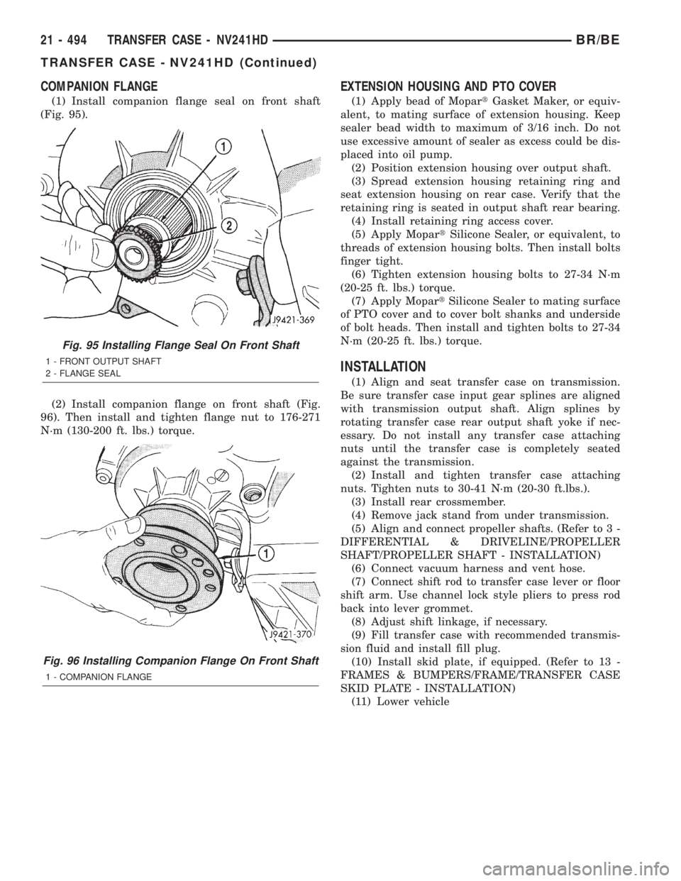
(1) Install companion flange seal on front shaft
(Fig. 95).
(2) Install companion flange on front shaft (Fig.
96). Then install and tighten flange nut to 176-271
N´m (130-200 ft. lbs.) torque.
EXTENSION HOUSING AND PTO COVER
(1) Apply bead of MopartGasket Maker, or equiv-
alent, to mating surface of extension housing. Keep
sealer bead width to maximum of 3/16 inch. Do not
use excessive amount of sealer as excess could be dis-
placed into oil pump.
(2) Position extension housing over output shaft.
(3) Spread extension housing retaining ring and
seat extension housing on rear case. Verify that the
retaining ring is seated in output shaft rear bearing.
(4) Install retaining ring access cover.
(5) Apply MopartSilicone Sealer, or equivalent, to
threads of extension housing bolts. Then install bolts
finger tight.
(6) Tighten extension housing bolts to 27-34 N´m
(20-25 ft. lbs.) torque.
(7) Apply MopartSilicone Sealer to mating surface
of PTO cover and to cover bolt shanks and underside
of bolt heads. Then install and tighten bolts to 27-34
N´m (20-25 ft. lbs.) torque.
INSTALLATION
(1) Align and seat transfer case on transmission.
Be sure transfer case input gear splines are aligned
with transmission output shaft. Align splines by
rotating transfer case rear output shaft yoke if nec-
essary. Do not install any transfer case attaching
nuts until the transfer case is completely seated
against the transmission.
(2) Install and tighten transfer case attaching
nuts. Tighten nuts to 30-41 N´m (20-30 ft.lbs.).
(3) Install rear crossmember.
(4) Remove jack stand from under transmission.
(5) Align and connect propeller shafts. (Refer to 3 -
DIFFERENTIAL & DRIVELINE/PROPELLER
SHAFT/PROPELLER SHAFT - INSTALLATION)
(6) Connect vacuum harness and vent hose.
(7) Connect shift rod to transfer case lever or floor
shift arm. Use channel lock style pliers to press rod
back into lever grommet.
(8) Adjust shift linkage, if necessary.
(9) Fill transfer case with recommended transmis-
sion fluid and install fill plug.
(10) Install skid plate, if equipped. (Refer to 13 -
FRAMES & BUMPERS/FRAME/TRANSFER CASE
SKID PLATE - INSTALLATION)
(11) Lower vehicle
Fig. 95 Installing Flange Seal On Front Shaft
1 - FRONT OUTPUT SHAFT
2 - FLANGE SEAL
Fig. 96 Installing Companion Flange On Front Shaft
1 - COMPANION FLANGE
21 - 494 TRANSFER CASE - NV241HDBR/BE
TRANSFER CASE - NV241HD (Continued)
Page 1948 of 2255
SPECIFICATIONS
TRANSFER CASE
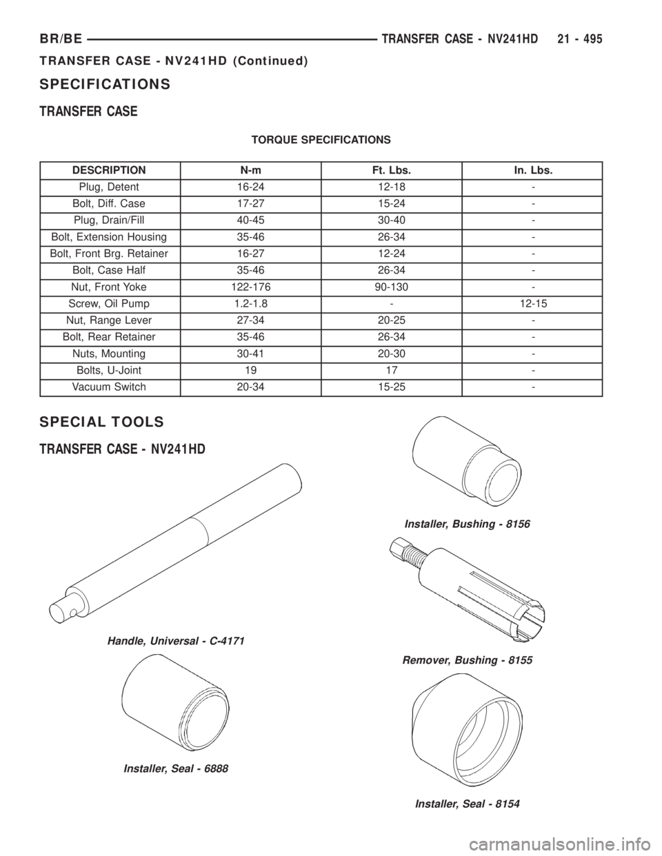
TORQUE SPECIFICATIONS
DESCRIPTION N-m Ft. Lbs. In. Lbs.
Plug, Detent 16-24 12-18 -
Bolt, Diff. Case 17-27 15-24 -
Plug, Drain/Fill 40-45 30-40 -
Bolt, Extension Housing 35-46 26-34 -
Bolt, Front Brg. Retainer 16-27 12-24 -
Bolt, Case Half 35-46 26-34 -
Nut, Front Yoke 122-176 90-130 -
Screw, Oil Pump 1.2-1.8 - 12-15
Nut, Range Lever 27-34 20-25 -
Bolt, Rear Retainer 35-46 26-34 -
Nuts, Mounting 30-41 20-30 -
Bolts, U-Joint 19 17 -
Vacuum Switch 20-34 15-25 -
SPECIAL TOOLS
TRANSFER CASE - NV241HD
Handle, Universal - C-4171
Installer, Seal - 6888
Installer, Bushing - 8156
Remover, Bushing - 8155
Installer, Seal - 8154
BR/BETRANSFER CASE - NV241HD 21 - 495
TRANSFER CASE - NV241HD (Continued)
Page 1952 of 2255
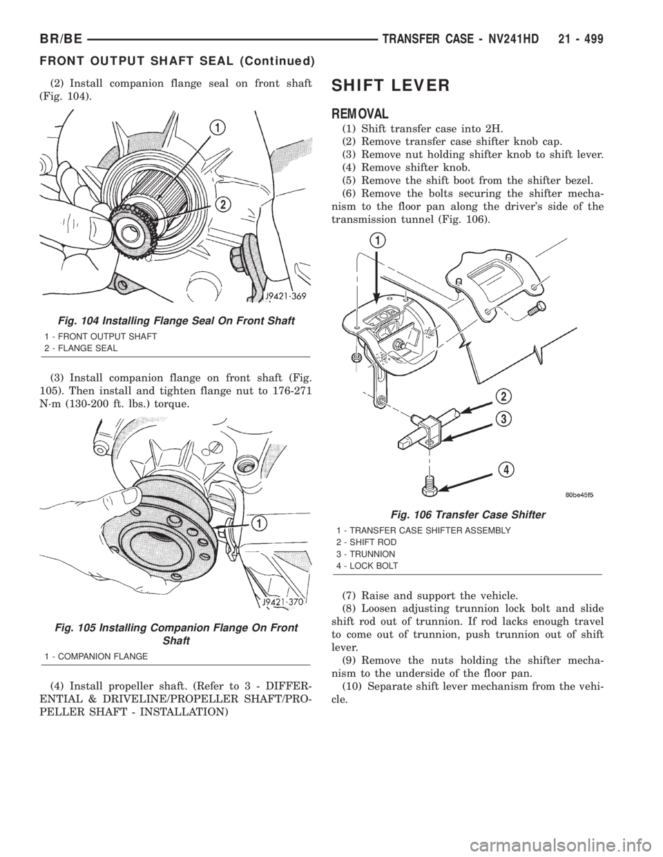
(2) Install companion flange seal on front shaft
(Fig. 104).
(3) Install companion flange on front shaft (Fig.
105). Then install and tighten flange nut to 176-271
N´m (130-200 ft. lbs.) torque.
(4) Install propeller shaft. (Refer to 3 - DIFFER-
ENTIAL & DRIVELINE/PROPELLER SHAFT/PRO-
PELLER SHAFT - INSTALLATION)SHIFT LEVER
REMOVAL
(1) Shift transfer case into 2H.
(2) Remove transfer case shifter knob cap.
(3) Remove nut holding shifter knob to shift lever.
(4) Remove shifter knob.
(5) Remove the shift boot from the shifter bezel.
(6) Remove the bolts securing the shifter mecha-
nism to the floor pan along the driver's side of the
transmission tunnel (Fig. 106).
(7) Raise and support the vehicle.
(8) Loosen adjusting trunnion lock bolt and slide
shift rod out of trunnion. If rod lacks enough travel
to come out of trunnion, push trunnion out of shift
lever.
(9) Remove the nuts holding the shifter mecha-
nism to the underside of the floor pan.
(10) Separate shift lever mechanism from the vehi-
cle.
Fig. 104 Installing Flange Seal On Front Shaft
1 - FRONT OUTPUT SHAFT
2 - FLANGE SEAL
Fig. 105 Installing Companion Flange On Front
Shaft
1 - COMPANION FLANGE
Fig. 106 Transfer Case Shifter
1 - TRANSFER CASE SHIFTER ASSEMBLY
2 - SHIFT ROD
3 - TRUNNION
4 - LOCK BOLT
BR/BETRANSFER CASE - NV241HD 21 - 499
FRONT OUTPUT SHAFT SEAL (Continued)