2002 DODGE RAM torque
[x] Cancel search: torquePage 2052 of 2255
VENT WINDOW
REMOVAL
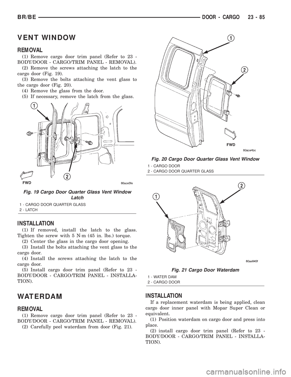
(1) Remove cargo door trim panel (Refer to 23 -
BODY/DOOR - CARGO/TRIM PANEL - REMOVAL).
(2) Remove the screws attaching the latch to the
cargo door (Fig. 19).
(3) Remove the bolts attaching the vent glass to
the cargo door (Fig. 20).
(4) Remove the glass from the door.
(5) If necessary, remove the latch from the glass.
INSTALLATION
(1) If removed, install the latch to the glass.
Tighten the screw with 5 N´m (45 in. lbs.) torque.
(2) Center the glass in the cargo door opening.
(3) Install the bolts attaching the vent glass to the
cargo door.
(4) Install the screws attaching the latch to the
cargo door.
(5) Install cargo door trim panel (Refer to 23 -
BODY/DOOR - CARGO/TRIM PANEL - INSTALLA-
TION).
WATERDAM
REMOVAL
(1) Remove cargo door trim panel (Refer to 23 -
BODY/DOOR - CARGO/TRIM PANEL - REMOVAL).
(2) Carefully peel waterdam from door (Fig. 21).
INSTALLATION
If a replacement waterdam is being applied, clean
cargo door inner panel with Mopar Super Clean or
equivalent.
(1) Position waterdam on cargo door and press into
place.
(2) install cargo door trim panel (Refer to 23 -
BODY/DOOR - CARGO/TRIM PANEL - INSTALLA-
TION).
Fig. 19 Cargo Door Quarter Glass Vent Window
Latch
1 - CARGO DOOR QUARTER GLASS
2-LATCH
Fig. 20 Cargo Door Quarter Glass Vent Window
1 - CARGO DOOR
2 - CARGO DOOR QUARTER GLASS
Fig. 21 Cargo Door Waterdam
1 - WATER DAM
2 - CARGO DOOR
BR/BEDOOR - CARGO 23 - 85
Page 2064 of 2255
CARGO BOX
REMOVAL
CAUTION: The bolts attaching the cargo box to the
frame are specially coated to provide a locking action.
These bolts are not reusable and must be replaced
each time the cargo box is removed or replaced.
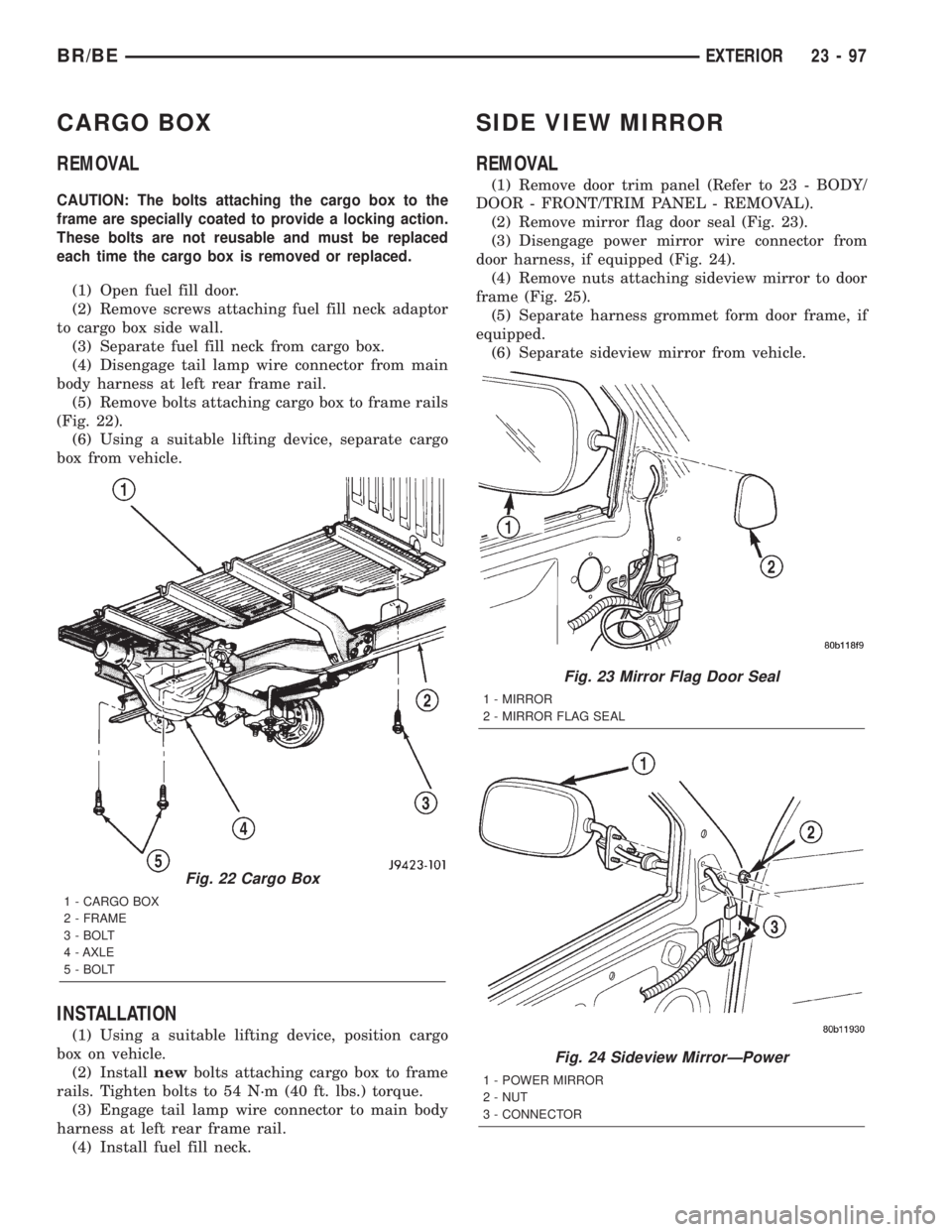
(1) Open fuel fill door.
(2) Remove screws attaching fuel fill neck adaptor
to cargo box side wall.
(3) Separate fuel fill neck from cargo box.
(4) Disengage tail lamp wire connector from main
body harness at left rear frame rail.
(5) Remove bolts attaching cargo box to frame rails
(Fig. 22).
(6) Using a suitable lifting device, separate cargo
box from vehicle.
INSTALLATION
(1) Using a suitable lifting device, position cargo
box on vehicle.
(2) Installnewbolts attaching cargo box to frame
rails. Tighten bolts to 54 N´m (40 ft. lbs.) torque.
(3) Engage tail lamp wire connector to main body
harness at left rear frame rail.
(4) Install fuel fill neck.
SIDE VIEW MIRROR
REMOVAL
(1) Remove door trim panel (Refer to 23 - BODY/
DOOR - FRONT/TRIM PANEL - REMOVAL).
(2) Remove mirror flag door seal (Fig. 23).
(3) Disengage power mirror wire connector from
door harness, if equipped (Fig. 24).
(4) Remove nuts attaching sideview mirror to door
frame (Fig. 25).
(5) Separate harness grommet form door frame, if
equipped.
(6) Separate sideview mirror from vehicle.
Fig. 22 Cargo Box
1 - CARGO BOX
2 - FRAME
3 - BOLT
4 - AXLE
5 - BOLT
Fig. 23 Mirror Flag Door Seal
1 - MIRROR
2 - MIRROR FLAG SEAL
Fig. 24 Sideview MirrorÐPower
1 - POWER MIRROR
2 - NUT
3 - CONNECTOR
BR/BEEXTERIOR 23 - 97
Page 2089 of 2255
SHIFT BOOT - MANUAL
TRANSMISSION
REMOVAL
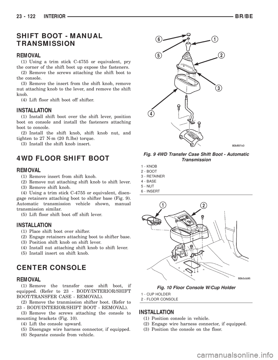
(1) Using a trim stick C-4755 or equivalent, pry
the corner of the shift boot up expose the fasteners.
(2) Remove the screws attaching the shift boot to
the console.
(3) Remove the insert from the shift knob, remove
nut attaching knob to the lever, and remove the shift
knob.
(4) Lift floor shift boot off shifter.
INSTALLATION
(1) Install shift boot over the shift lever, position
boot on console and install the fasteners attaching
boot to concole.
(2) Install the shift knob, shift knob nut, and
tighten to 27 N´m (20 ft.lbs) torque.
(3) Install the shift knob insert.
4WD FLOOR SHIFT BOOT
REMOVAL
(1) Remove insert from shift knob.
(2) Remove nut attaching shift knob to shift lever.
(3) Remove shift knob.
(4) Using a trim stick C-4755 or equivalent, disen-
gage retainers attaching boot to shifter base (Fig. 9).
Automatic transmission vehicle shown, manual
transmission similar.
(5) Lift floor shift boot off shift lever.
INSTALLATION
(1) Place shift boot over shifter.
(2) Engage retainers attaching boot to shifter base.
(3) Position shift knob on shift lever.
(4) Install nut attaching shift knob to shift lever.
(5) Install insert on shift knob.
CENTER CONSOLE
REMOVAL
(1) Remove the transfer case shift boot, if
equipped. (Refer to 23 - BODY/INTERIOR/SHIFT
BOOT/TRANSFER CASE - REMOVAL).
(2) Remove the tranmission shifter boot. (Refer to
23 - BODY/INTERIOR/SHIFT BOOT - REMOVAL).
(3) Remove the screws attaching the console to
mounting brackets (Fig. 10).
(4) Lift the console upward.
(5) Disengage wire harness connector, if equipped.
(6) Separate console from vehicle.
INSTALLATION
(1) Position console in vehicle.
(2) Engage wire harness connector, if equipped.
(3) Position the console on the floor.
Fig. 9 4WD Transfer Case Shift Boot - Automatic
Transmission
1 - KNOB
2 - BOOT
3 - RETAINER
4 - BASE
5 - NUT
6 - INSERT
Fig. 10 Floor Console W/Cup Holder
1 - CUP HOLDER
2 - FLOOR CONSOLE
23 - 122 INTERIORBR/BE
Page 2093 of 2255
BODY VENT
REMOVAL
(1) Open door.
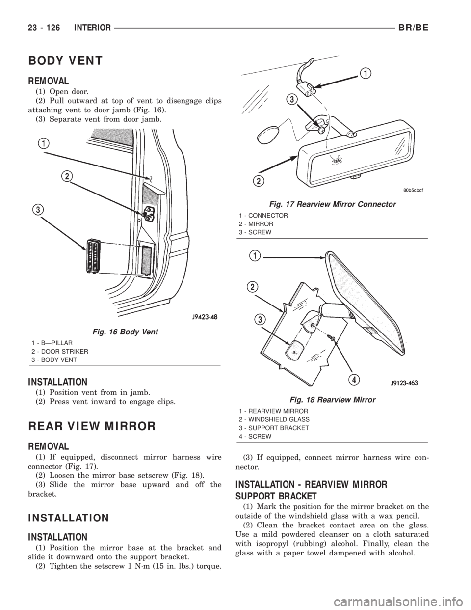
(2) Pull outward at top of vent to disengage clips
attaching vent to door jamb (Fig. 16).
(3) Separate vent from door jamb.
INSTALLATION
(1) Position vent from in jamb.
(2) Press vent inward to engage clips.
REAR VIEW MIRROR
REMOVAL
(1) If equipped, disconnect mirror harness wire
connector (Fig. 17).
(2) Loosen the mirror base setscrew (Fig. 18).
(3) Slide the mirror base upward and off the
bracket.
INSTALLATION
INSTALLATION
(1) Position the mirror base at the bracket and
slide it downward onto the support bracket.
(2) Tighten the setscrew 1 N´m (15 in. lbs.) torque.(3) If equipped, connect mirror harness wire con-
nector.
INSTALLATION - REARVIEW MIRROR
SUPPORT BRACKET
(1) Mark the position for the mirror bracket on the
outside of the windshield glass with a wax pencil.
(2) Clean the bracket contact area on the glass.
Use a mild powdered cleanser on a cloth saturated
with isopropyl (rubbing) alcohol. Finally, clean the
glass with a paper towel dampened with alcohol.
Fig. 16 Body Vent
1 - BÐPILLAR
2 - DOOR STRIKER
3 - BODY VENT
Fig. 17 Rearview Mirror Connector
1 - CONNECTOR
2 - MIRROR
3 - SCREW
Fig. 18 Rearview Mirror
1 - REARVIEW MIRROR
2 - WINDSHIELD GLASS
3 - SUPPORT BRACKET
4 - SCREW
23 - 126 INTERIORBR/BE
Page 2099 of 2255
INSTALLATION
(1) Align console lid with console. Verify lid tension
spring is in position.
(2) Install hinge pin.
(3) Position trim bezel on lid and snap into place.
CENTER SEAT ARMREST/
CONSOLE
REMOVAL
(1) Remove bolts on driver and passenger seat
inboard seat tracks.
(2) Separate center section.
INSTALLATION
(1) Position and align center section on driver and
passenger seat inboard seat tracks.
(2) Install bolts. Tighten to 19.5 N´m (14 ft. lbs.)
torque.
CENTER SEAT ARMREST/
LATCH COVER
REMOVAL
(1) With the seat back fully forward, move the
driver's seat to a full forward position.
(2) Place the center arm rest in a full up position.
(3) Remove the fastener securing the cover to the
inertia latch.
(4) Disengage the front edge of the cover, then
lower the arm rest.
(5) Remove the inertia latch cover by pulling the
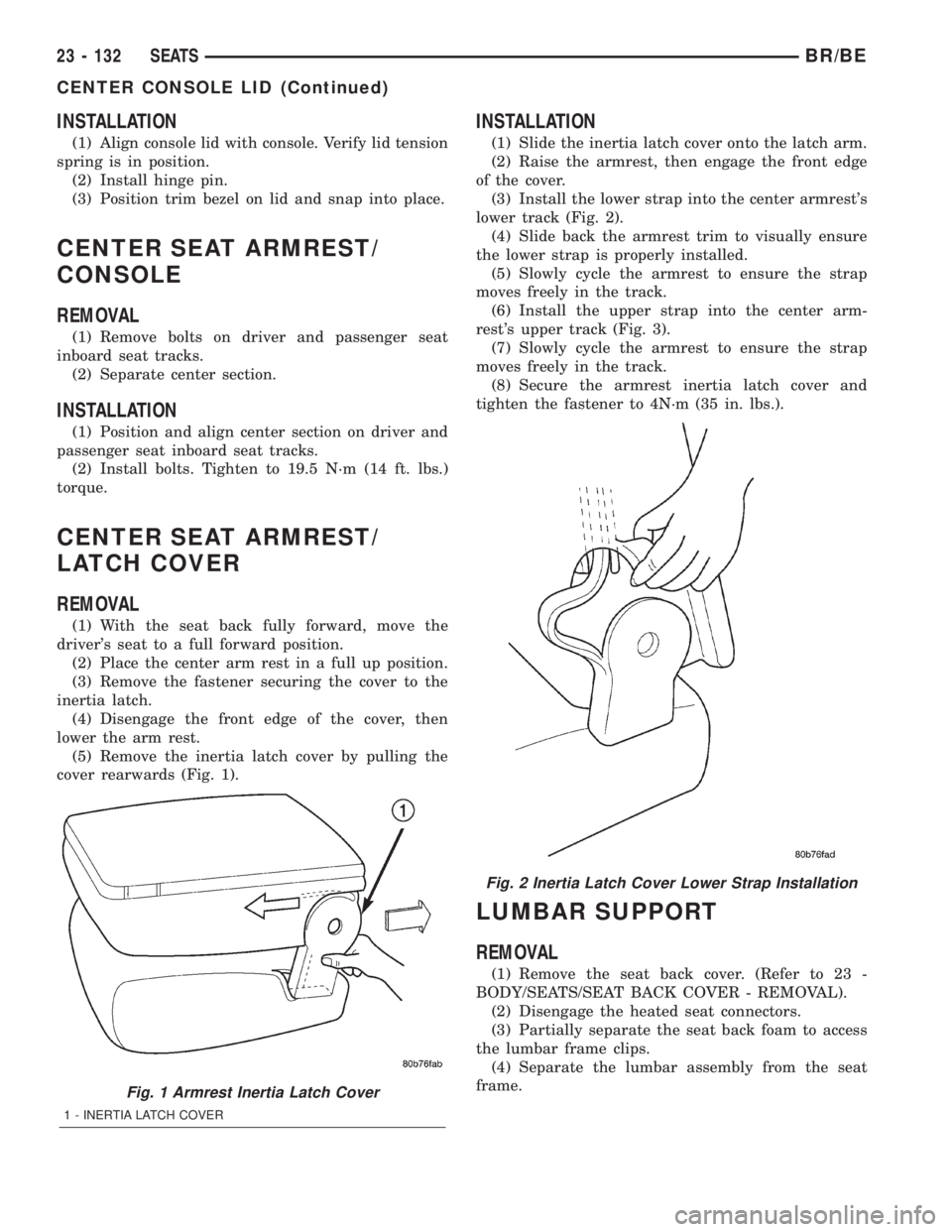
cover rearwards (Fig. 1).
INSTALLATION
(1) Slide the inertia latch cover onto the latch arm.
(2) Raise the armrest, then engage the front edge
of the cover.
(3) Install the lower strap into the center armrest's
lower track (Fig. 2).
(4) Slide back the armrest trim to visually ensure
the lower strap is properly installed.
(5) Slowly cycle the armrest to ensure the strap
moves freely in the track.
(6) Install the upper strap into the center arm-
rest's upper track (Fig. 3).
(7) Slowly cycle the armrest to ensure the strap
moves freely in the track.
(8) Secure the armrest inertia latch cover and
tighten the fastener to 4N´m (35 in. lbs.).
LUMBAR SUPPORT
REMOVAL
(1) Remove the seat back cover. (Refer to 23 -
BODY/SEATS/SEAT BACK COVER - REMOVAL).
(2) Disengage the heated seat connectors.
(3) Partially separate the seat back foam to access
the lumbar frame clips.
(4) Separate the lumbar assembly from the seat
frame.
Fig. 1 Armrest Inertia Latch Cover
1 - INERTIA LATCH COVER
Fig. 2 Inertia Latch Cover Lower Strap Installation
23 - 132 SEATSBR/BE
CENTER CONSOLE LID (Continued)
Page 2100 of 2255
INSTALLATION
(1) Position the lumbar assembly on the seat back
frame.
(2) Engage the retaining clips on the seat frame.
(3) Route the lumbar wire harness through seat
assembly.
(4) Engage the heated seat wire connectors.
(5) Install the seat back cover. (Refer to 23 -
BODY/SEATS/SEAT BACK COVER - INSTALLA-
TION).
(6) Perform a function check on the seat opera-
tions.
SEAT - BENCH SEAT
REMOVAL
(1) Move seat track to forward position.
(2) Hinge seat backs forward.
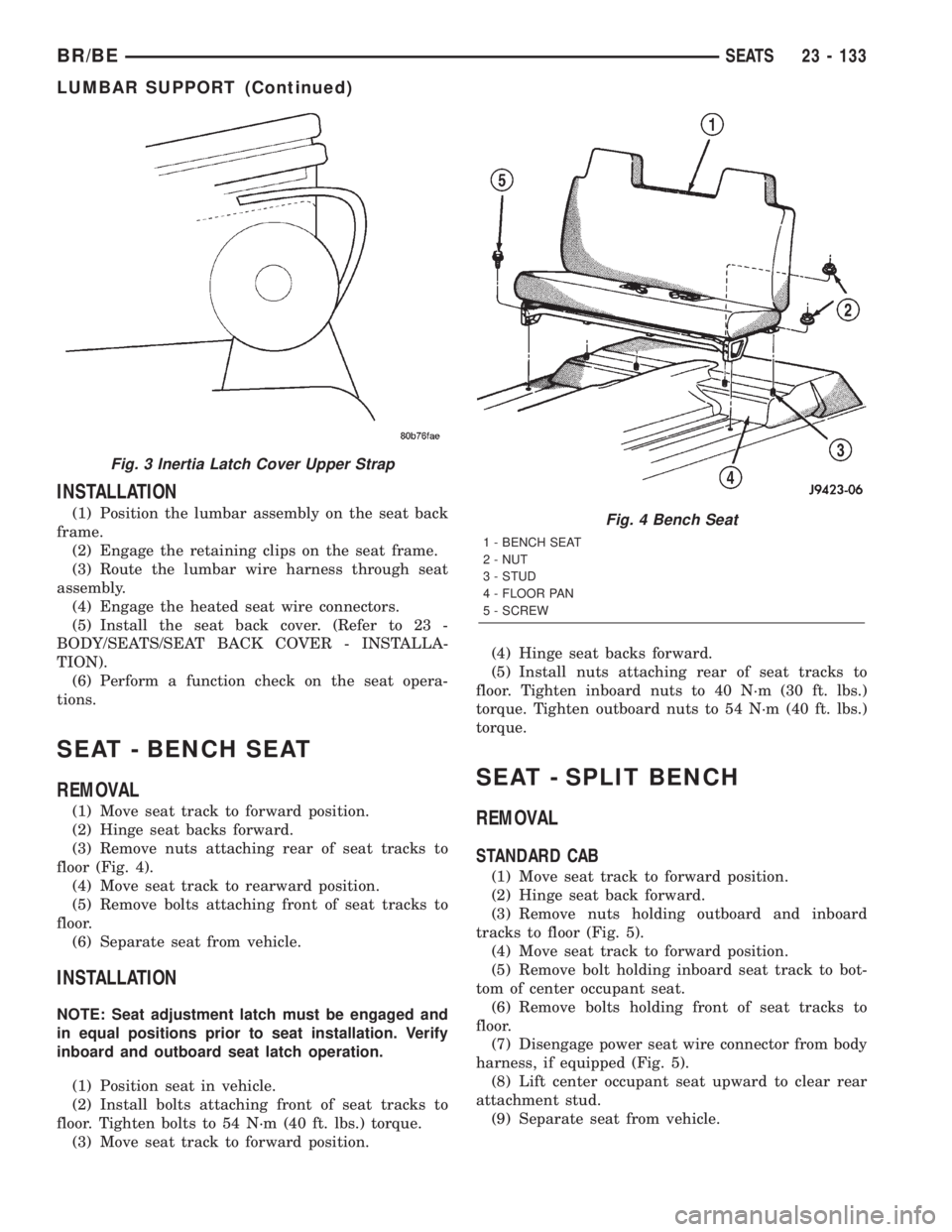
(3) Remove nuts attaching rear of seat tracks to
floor (Fig. 4).
(4) Move seat track to rearward position.
(5) Remove bolts attaching front of seat tracks to
floor.
(6) Separate seat from vehicle.
INSTALLATION
NOTE: Seat adjustment latch must be engaged and
in equal positions prior to seat installation. Verify
inboard and outboard seat latch operation.
(1) Position seat in vehicle.
(2) Install bolts attaching front of seat tracks to
floor. Tighten bolts to 54 N´m (40 ft. lbs.) torque.
(3) Move seat track to forward position.(4) Hinge seat backs forward.
(5) Install nuts attaching rear of seat tracks to
floor. Tighten inboard nuts to 40 N´m (30 ft. lbs.)
torque. Tighten outboard nuts to 54 N´m (40 ft. lbs.)
torque.
SEAT - SPLIT BENCH
REMOVAL
STANDARD CAB
(1) Move seat track to forward position.
(2) Hinge seat back forward.
(3) Remove nuts holding outboard and inboard
tracks to floor (Fig. 5).
(4) Move seat track to forward position.
(5) Remove bolt holding inboard seat track to bot-
tom of center occupant seat.
(6) Remove bolts holding front of seat tracks to
floor.
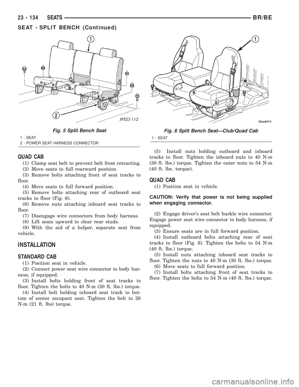
(7) Disengage power seat wire connector from body
harness, if equipped (Fig. 5).
(8) Lift center occupant seat upward to clear rear
attachment stud.
(9) Separate seat from vehicle.
Fig. 3 Inertia Latch Cover Upper Strap
Fig. 4 Bench Seat
1 - BENCH SEAT
2 - NUT
3 - STUD
4 - FLOOR PAN
5 - SCREW
BR/BESEATS 23 - 133
LUMBAR SUPPORT (Continued)
Page 2101 of 2255
QUAD CAB
(1) Clamp seat belt to prevent belt from retracting.
(2) Move seats to full rearward position.
(3) Remove bolts attaching front of seat tracks to
floor.
(4) Move seats to full forward position.
(5) Remove bolts attaching rear of outboard seat
tracks to floor (Fig. 6).
(6) Remove nuts attaching inboard seat tracks to
floor.
(7) Disengage wire connectors from body harness.
(8) Lift seats upward to clear rear studs.
(9) With the aid of a helper, separate seat from
vehicle.
INSTALLATION
STANDARD CAB
(1) Position seat in vehicle.
(2) Connect power seat wire connector to body har-
ness, if equipped.
(3) Install bolts holding front of seat tracks to
floor. Tighten the bolts to 40 N´m (30 ft. lbs.) torque.
(4) Install bolt holding inboard seat track to bot-
tom of center occupant seat. Tighten the bolt to 28
N´m (21 ft. lbs) torque.(5) Install nuts holding outboard and inboard
tracks to floor. Tighten the inboard nuts to 40 N´m
(30 ft. lbs.) torque. Tighten the outer nuts to 54 N´m
(40 ft. lbs. torque).
QUAD CAB
(1) Position seat in vehicle.
CAUTION: Verify that power is not being supplied
when engaging connector.
(2) Engage driver's seat belt buckle wire connector.
Engage power seat wire connector to body harness, if
equipped.
(3) Ensure seats are in full forward position.
(4) Install outboard bolts attaching rear of seat
tracks to floor (Fig. 6). Tighten the bolts to 54 N´m
(40 ft. lbs.) torque.
(5) Install nuts attaching inboard seat tracks to
floor. Tighten the nuts to 40 N´m (30 ft. lbs.) torque.
(6) Move seats to full forward position.
(7) Install bolts attaching front of seat tracks to
floor. Tighten the bolts to 54 N´m (40 ft. lbs.) torque.
Fig. 5 Split Bench Seat
1 - SEAT
2 - POWER SEAT HARNESS CONNECTOR
Fig. 6 Split Bench SeatÐClub/Quad Cab
1 - SEAT
23 - 134 SEATSBR/BE
SEAT - SPLIT BENCH (Continued)
Page 2102 of 2255
SEAT BACK - BENCH SEAT
REMOVAL
(1) Move seat to the full forward position.
(2) Release J-Strap and peel back side of cover
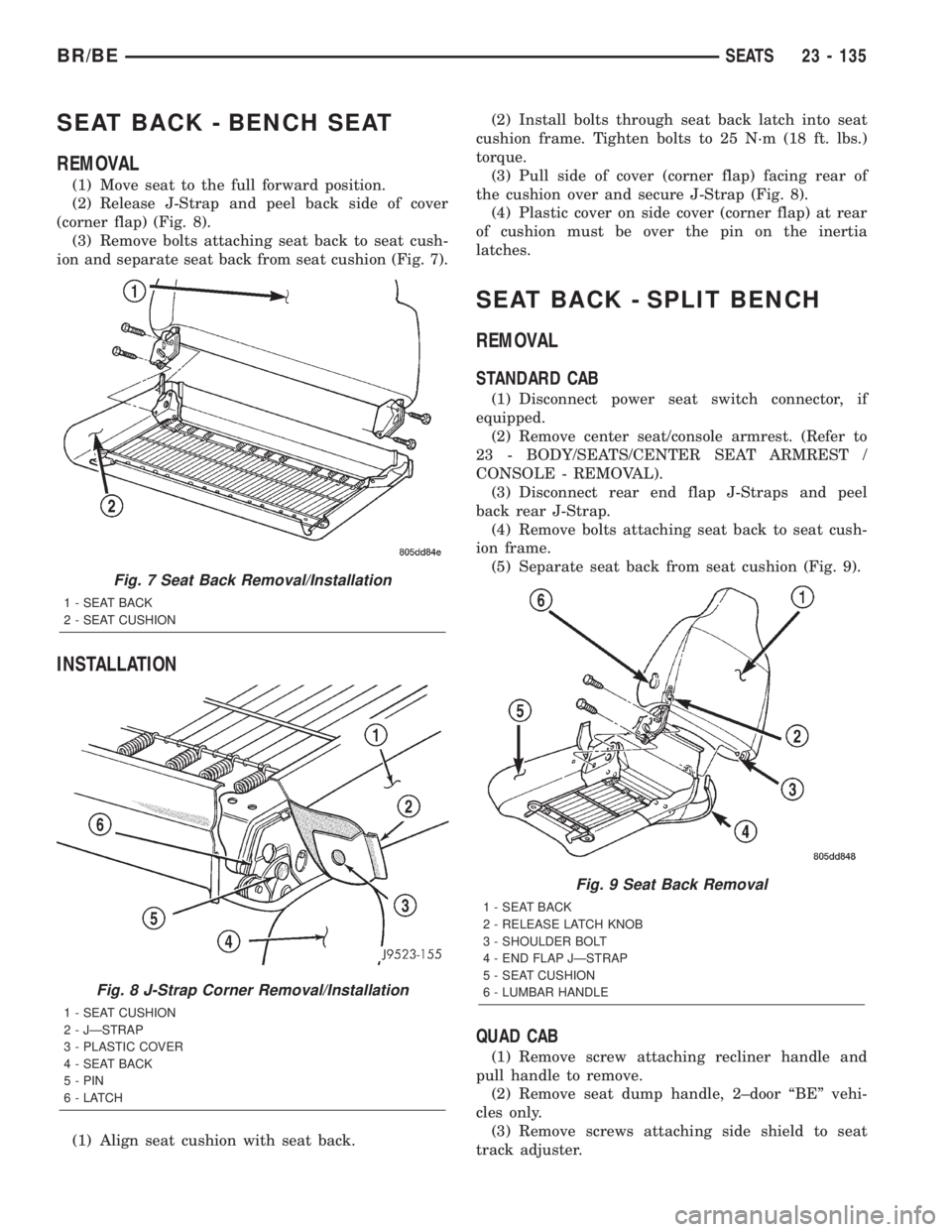
(corner flap) (Fig. 8).
(3) Remove bolts attaching seat back to seat cush-
ion and separate seat back from seat cushion (Fig. 7).
INSTALLATION
(1) Align seat cushion with seat back.(2) Install bolts through seat back latch into seat
cushion frame. Tighten bolts to 25 N´m (18 ft. lbs.)
torque.
(3) Pull side of cover (corner flap) facing rear of
the cushion over and secure J-Strap (Fig. 8).
(4) Plastic cover on side cover (corner flap) at rear
of cushion must be over the pin on the inertia
latches.
SEAT BACK - SPLIT BENCH
REMOVAL
STANDARD CAB
(1) Disconnect power seat switch connector, if
equipped.
(2) Remove center seat/console armrest. (Refer to
23 - BODY/SEATS/CENTER SEAT ARMREST /
CONSOLE - REMOVAL).
(3) Disconnect rear end flap J-Straps and peel
back rear J-Strap.
(4) Remove bolts attaching seat back to seat cush-
ion frame.
(5) Separate seat back from seat cushion (Fig. 9).
QUAD CAB
(1) Remove screw attaching recliner handle and
pull handle to remove.
(2) Remove seat dump handle, 2±door ªBEº vehi-
cles only.
(3) Remove screws attaching side shield to seat
track adjuster.
Fig. 7 Seat Back Removal/Installation
1 - SEAT BACK
2 - SEAT CUSHION
Fig. 8 J-Strap Corner Removal/Installation
1 - SEAT CUSHION
2 - JÐSTRAP
3 - PLASTIC COVER
4 - SEAT BACK
5 - PIN
6-LATCH
Fig. 9 Seat Back Removal
1 - SEAT BACK
2 - RELEASE LATCH KNOB
3 - SHOULDER BOLT
4 - END FLAP JÐSTRAP
5 - SEAT CUSHION
6 - LUMBAR HANDLE
BR/BESEATS 23 - 135