2002 DODGE RAM torque
[x] Cancel search: torquePage 2117 of 2255
QUARTER WINDOW
REMOVAL
(1) Remove quarter trim panel.
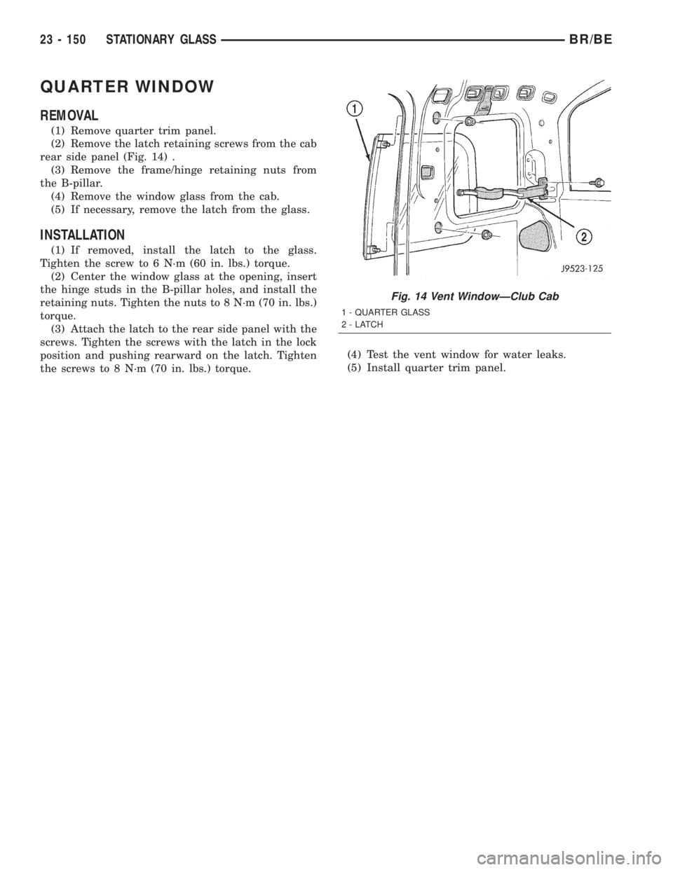
(2) Remove the latch retaining screws from the cab
rear side panel (Fig. 14) .
(3) Remove the frame/hinge retaining nuts from
the B-pillar.
(4) Remove the window glass from the cab.
(5) If necessary, remove the latch from the glass.
INSTALLATION
(1) If removed, install the latch to the glass.
Tighten the screw to 6 N´m (60 in. lbs.) torque.
(2) Center the window glass at the opening, insert
the hinge studs in the B-pillar holes, and install the
retaining nuts. Tighten the nuts to 8 N´m (70 in. lbs.)
torque.
(3) Attach the latch to the rear side panel with the
screws. Tighten the screws with the latch in the lock
position and pushing rearward on the latch. Tighten
the screws to 8 N´m (70 in. lbs.) torque.(4) Test the vent window for water leaks.
(5) Install quarter trim panel.
Fig. 14 Vent WindowÐClub Cab
1 - QUARTER GLASS
2-LATCH
23 - 150 STATIONARY GLASSBR/BE
Page 2129 of 2255
Item Description Notes
Blower Motor hardwired to
control headresistor block
Cooling Fan viscous fan
Clutch
Control relay PCM
Draw 2 - 3.9 amps @
12V 0.5V @ 70É
FItem Description Notes
Gap 0.0169- 0.0319
DRB IIIT
Reads TPS, RPM, A/C
switch test
Actuators clutch relay
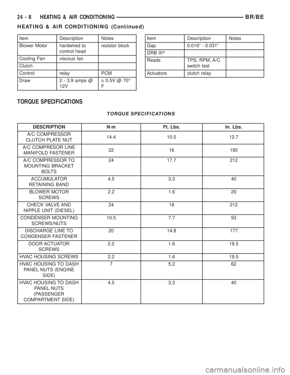
TORQUE SPECIFICATIONS
TORQUE SPECIFICATIONS
DESCRIPTION N´m Ft. Lbs. In. Lbs.
A/C COMPRESSOR
CLUTCH PLATE NUT14.4 10.5 12.7
A/C COMPRESOR LINE
MANIFOLD FASTENER22 16 195
A/C COMPRESSOR TO
MOUNTING BRACKET
BOLTS24 17.7 212
ACCUMULATOR
RETAINING BAND4.5 3.3 40
BLOWER MOTOR
SCREWS2.2 1.6 20
CHECK VALVE AND
NIPPLE UNIT (DIESEL)24 18 212
CONDENSER MOUNTING
SCREWS/NUTS10.5 7.7 93
DISCHARGE LINE TO
CONDENSER FASTENER20 14.8 177
DOOR ACTUATOR
SCREWS2.2 1.6 19.5
HVAC HOUSING SCREWS 2.2 1.6 19.5
HVAC HOUSING TO DASH
PANEL NUTS (ENGINE
SIDE)7 5.2 62
HVAC HOUSING TO DASH
PANEL NUTS
(PASSENGER
COMPARTMENT SIDE)4.5 3.3 40
24 - 8 HEATING & AIR CONDITIONINGBR/BE
HEATING & AIR CONDITIONING (Continued)
Page 2134 of 2255
OPERATION
The compressor clutch assembly provides the
means to engage and disengage the compressor from
the engine serpentine accessory drive belt. When the
clutch coil is energized, it magnetically draws the
clutch into contact with the pulley and drives the
compressor shaft. When the coil is not energized, the
pulley freewheels on the clutch hub bearing, which is
part of the pulley. The compressor clutch and coil are
the only serviced parts on the compressor.
The compressor clutch engagement is controlled by
several components: the a/c heater mode control
switch, the a/c loss of charge switch, the a/c pressure
transducer, the compressor clutch relay, the evapora-
tor temperature sensor and the Powertrain Control
Module (PCM). The PCM may delay compressor
clutch engagement for up to thirty seconds(Refer to 8
- ELECTRICAL/ELECTRONIC CONTROL MOD-
ULES/POWERTRAIN CONTROL MODULE -
DESCRIPTION).
DIAGNOSIS AND TESTING - A/C COMPRESSOR
CLUTCH COIL
For circuit descriptions and diagrams, (Refer to
Appropriate Wiring Information). The battery must
be fully-charged before performing the following
tests. Refer to Battery for more information.
(1) Connect an ammeter (0 to 10 ampere scale) in
series with the clutch coil terminal. Use a voltmeter
(0 to 20 volt scale) with clip-type leads for measuring
the voltage across the battery and the compressor
clutch coil.(2) With the a/c heater mode control switch in any
A/C mode, and the blower motor switch in the lowest
speed position, start the engine and run it at normal
idle.
(3) The compressor clutch coil voltage should read
within 0.2 volts of the battery voltage. If there is
voltage at the clutch coil, but the reading is not
within 0.2 volts of the battery voltage, test the clutch
coil feed circuit for excessive voltage drop and repair
as required. If there is no voltage reading at the
clutch coil, use a DRB IIItscan tool and (Refer to
Appropriate Diagnostic Information) for testing of the
compressor clutch circuit. The following components
must be checked and repaired as required before you
can complete testing of the clutch coil:
²Fuses in the junction block and the Power Dis-
tribution Center (PDC)
²A/C Heater mode control switch
²Compressor clutch relay
²A/C High Pressure Switch
²A/C Low Pressure Switch
²Powertrain Control Module (PCM).
(4) The compressor clutch coil is acceptable if the
current draw measured at the clutch coil is 2.0 to 3.9
amperes with the electrical system voltage at 11.5 to
12.5 volts. This should only be checked with the work
area temperature at 21É C (70É F). If system voltage
is more than 12.5 volts, add electrical loads by turn-
ing on electrical accessories until the system voltage
drops below 12.5 volts.
(a) If the clutch coil current reading is four
amperes or more, the coil is shorted and should be
replaced.
(b) If the clutch coil current reading is zero, the
coil is open and should be replaced.
STANDARD PROCEDURE - A/C COMPRESSOR
CLUTCH BREAK-IN
After a new compressor clutch has been installed,
cycle the compressor clutch approximately twenty
times (five seconds on, then five seconds off). During
this procedure, set the A/C Heater control to the
Recirculation Mode, the blower motor switch in the
highest speed position, and the engine speed at 1500
to 2000 rpm. This procedure (burnishing) will seat
the opposing friction surfaces and provide a higher
compressor clutch torque capability.
REMOVAL
The refrigerant system can remain fully-charged
during compressor clutch, pulley, or coil replacement.
The compressor clutch can be serviced in the vehicle.
(1) Disconnect and isolate the battery negative
cable.
(2) On models with the diesel engine option,
remove the compressor from the engine. Do not
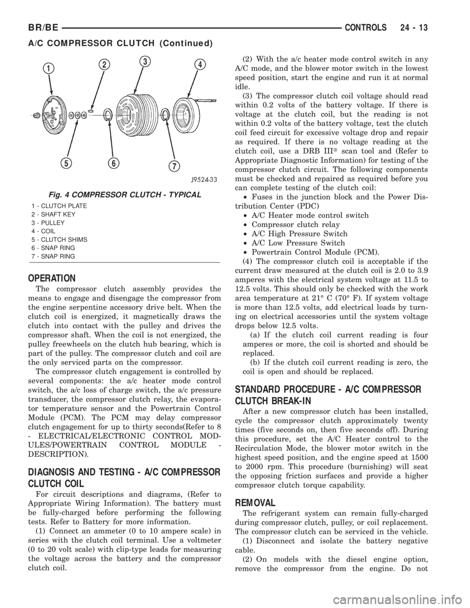
Fig. 4 COMPRESSOR CLUTCH - TYPICAL
1 - CLUTCH PLATE
2 - SHAFT KEY
3 - PULLEY
4 - COIL
5 - CLUTCH SHIMS
6 - SNAP RING
7 - SNAP RING
BR/BECONTROLS 24 - 13
A/C COMPRESSOR CLUTCH (Continued)
Page 2163 of 2255
SERVICE WARNINGS
WARNING:
THE AIR CONDITIONING SYSTEM CONTAINS
REFRIGERANT UNDER HIGH PRESSURE. SEVERE
PERSONAL INJURY MAY RESULT FROM IMPROPER
SERVICE PROCEDURES. REPAIRS SHOULD ONLY
BE PERFORMED BY QUALIFIED SERVICE PERSON-
NEL.
AVOID BREATHING THE REFRIGERANT AND
REFRIGERANT OIL VAPOR OR MIST. EXPOSURE
MAY IRRITATE THE EYES, NOSE, AND/OR THROAT.
WEAR EYE PROTECTION WHEN SERVICING THE
AIR CONDITIONING REFRIGERANT SYSTEM. SERI-
OUS EYE INJURY CAN RESULT FROM DIRECT
CONTACT WITH THE REFRIGERANT. IF EYE CON-
TACT OCCURS, SEEK MEDICAL ATTENTION IMME-
DIATELY.
DO NOT EXPOSE THE REFRIGERANT TO OPEN
FLAME. POISONOUS GAS IS CREATED WHEN
REFRIGERANT IS BURNED. AN ELECTRONIC LEAK
DETECTOR IS RECOMMENDED.
IF ACCIDENTAL SYSTEM DISCHARGE OCCURS,
VENTILATE THE WORK AREA BEFORE RESUMING
SERVICE. LARGE AMOUNTS OF REFRIGERANT
RELEASED IN A CLOSED WORK AREA WILL DIS-
PLACE THE OXYGEN AND CAUSE SUFFOCATION.
THE EVAPORATION RATE OF R-134a REFRIGER-
ANT AT AVERAGE TEMPERATURE AND ALTITUDE
IS EXTREMELY HIGH. AS A RESULT, ANYTHING
THAT COMES IN CONTACT WITH THE REFRIGER-
ANT WILL FREEZE. ALWAYS PROTECT THE SKIN
OR DELICATE OBJECTS FROM DIRECT CONTACT
WITH THE REFRIGERANT.
THE R-134a SERVICE EQUIPMENT OR THE VEHI-
CLE REFRIGERANT SYSTEM SHOULD NOT BE
PRESSURE TESTED OR LEAK TESTED WITH COM-
PRESSED AIR. SOME MIXTURES OF AIR AND
R-134a HAVE BEEN SHOWN TO BE COMBUSTIBLE
AT ELEVATED PRESSURES. THESE MIXTURES ARE
POTENTIALLY DANGEROUS, AND MAY RESULT IN
FIRE OR EXPLOSION CAUSING INJURY OR PROP-
ERTY DAMAGE.
SERVICE CAUTIONS
CAUTION: Liquid refrigerant is corrosive to metal
surfaces. Follow the operating instructions supplied
with the service equipment being used.
Never add R-12 to a refrigerant system designed to
use R-134a. Damage to the system will result.
R-12 refrigerant oil must not be mixed with R-134a
refrigerant oil. They are not compatible.
Do not use R-12 equipment or parts on the R-134a
system. Damage to the system will result.Do not overcharge the refrigerant system. This will
cause excessive compressor head pressure and
can cause noise and system failure.
Recover the refrigerant before opening any fitting
or connection. Open the fittings with caution, even
after the system has been discharged. Never open
or loosen a connection before recovering the refrig-
erant.
Do not remove the secondary retention clip from
any spring-lock coupler connection while the refrig-
erant system is under pressure. Recover the refrig-
erant before removing the secondary retention clip.
Open the fittings with caution, even after the sys-
tem has been discharged. Never open or loosen a
connection before recovering the refrigerant.
The refrigerant system must always be evacuated
before charging.
Do not open the refrigerant system or uncap a
replacement component until you are ready to ser-
vice the system. This will prevent contamination in
the system.
Before disconnecting a component, clean the out-
side of the fittings thoroughly to prevent contami-
nation from entering the refrigerant system.
Immediately after disconnecting a component from
the refrigerant system, seal the open fittings with a
cap or plug.
Before connecting an open refrigerant fitting,
always install a new seal or gasket. Coat the fitting
and seal with clean refrigerant oil before connect-
ing.
Do not remove the sealing caps from a replacement
component until it is to be installed.
When installing a refrigerant line, avoid sharp
bends that may restrict refrigerant flow. Position the
refrigerant lines away from exhaust system compo-
nents or any sharp edges, which may damage the
line.
Tighten refrigerant fittings only to the specified
torque. The aluminum fittings used in the refriger-
ant system will not tolerate overtightening.
When disconnecting a refrigerant fitting, use a
wrench on both halves of the fitting. This will pre-
vent twisting of the refrigerant lines or tubes.
Refrigerant oil will absorb moisture from the atmo-
sphere if left uncapped. Do not open a container of
refrigerant oil until you are ready to use it. Replace
the cap on the oil container immediately after using.
Store refrigerant oil only in a clean, airtight, and
moisture-free container.
Keep service tools and the work area clean. Con-
tamination of the refrigerant system through care-
less work habits must be avoided.
24 - 42 PLUMBINGBR/BE
PLUMBING (Continued)
Page 2189 of 2255
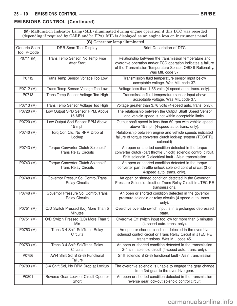
(M)Malfunction Indicator Lamp (MIL) illuminated during engine operation if this DTC was recorded
(depending if required by CARB and/or EPA). MIL is displayed as an engine icon on instrument panel.
(G)Generator lamp illuminated
Generic Scan
Tool P-CodeDRB Scan Tool Display Brief Description of DTC
P0711 (M) Trans Temp Sensor, No Temp Rise
After StartRelationship between the transmission temperature and
overdrive operation and/or TCC operation indicates a failure
of the Transmission Temperature Sensor. OBD II Rationality.
Was MIL code 37.
P0712 Trans Temp Sensor Voltage Too Low Transmission fluid temperature sensor input below
acceptable voltage. Was MIL code 37.
P0712 (M) Trans Temp Sensor Voltage Too Low Voltage less than 1.55 volts (4-speed auto. trans. only).
P0713 Trans Temp Sensor Voltage Too High Transmission fluid temperature sensor input above
acceptable voltage. Was MIL code 37.
P0713 (M) Trans Temp Sensor Voltage Too High Voltage greater than 3.76 volts (4-speed auto. trans. only).
P0720 (M) Low Output SPD Sensor RPM, Above
15 MPHThe relationship between the Output Shaft Speed Sensor
and vehicle speed is not within acceptable limits.
P0720 (M) Low Output Spd Sensor RPM Above
15 mphOutput shaft speed is less than 60 rpm with vehicle speed
above 15 mph (4-speed auto. trans. only).
P0740 (M) Torq Con Clu, No RPM Drop at
LockupRelationship between engine and vehicle speeds indicated
failure of torque convertor clutch lock-up system (TCC/PTU
solenoid)
P0743 (M) Torque Converter Clutch Solenoid/
Trans Relay CircuitsAn open or shorted condition detected in the torque
converter clutch (part throttle unlock) solenoid control circuit.
Shift solenoid C electrical fault - Aisin transmission
P0743 (M) Torque Converter Clutch Solenoid/
Trans Relay CircuitsAn open or shorted condition detected in the torque
converter part throttle unlock solenoid control circuit (3 or
4-speed auto. trans. only).
P0748 (M) Governor Pressur Sol Control/Trans
Relay CircuitsAn open or shorted condition detected in the Governor
Pressure Solenoid circuit or Trans Relay Circuit in JTEC RE
transmissions.
P0748 (M) Governor Pressure Sol Control/Trans
Relay CircuitsAn open or shorted condition detected in the governor
pressure solenoid or relay circuits (4-speed auto. trans.
only).
P0751 (M) O/D Switch Pressed (Lo) More Than 5
MinutesOverdrive override switch input is in a prolonged depressed
state.
P0751 (M) O/D Switch Pressed (LO) More Than 5
MinOverdrive Off switch input too low for more than 5 minutes
(4-speed auto. trans. only).
P0753 (M) Trans 3-4 Shift Sol/Trans Relay
CircuitsAn open or shorted condition detected in the overdrive
solenoid control circuit or Trans Relay Circuit in JTEC RE
transmissions. Was MIL code 45.
P0753 (M) Trans 3-4 Shift Sol/Trans Relay
CircuitsAn open or shorted condition detected in the transmission
2-4 shift solenoid circuit (4-speed auto. trans. only).
P0756 AW4 Shift Sol B (2-3) Functional
FailureShift solenoid B (2-3) functional fault - Aisin transmission
P0783 (M) 3-4 Shift Sol, No RPM Drop at Lockup The overdrive solenoid is unable to engage the gear change
from 3rd gear to the overdrive gear.
P0801 Reverse Gear Lockout Circuit Open or
ShortAn open or shorted condition detected in the transmission
reverse gear lock-out solenoid control circuit.
25 - 10 EMISSIONS CONTROLBR/BE
EMISSIONS CONTROL (Continued)
Page 2197 of 2255
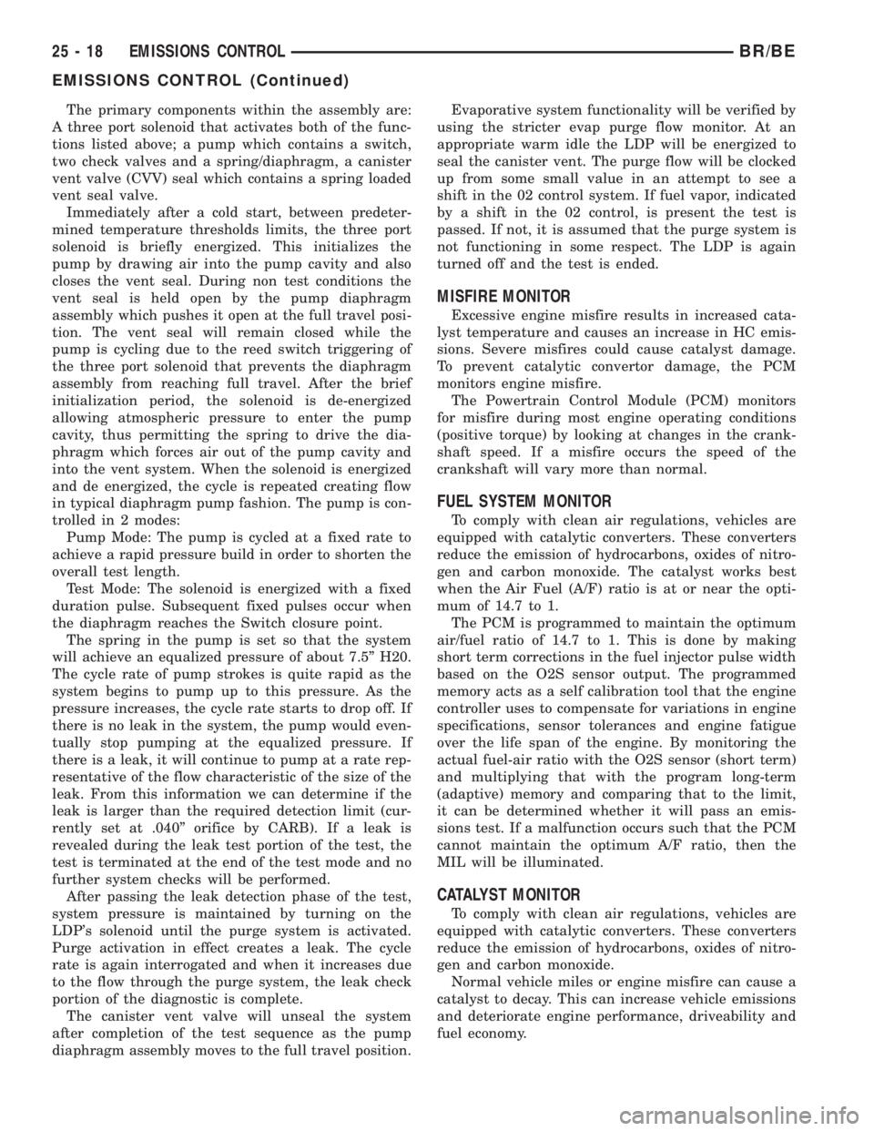
The primary components within the assembly are:
A three port solenoid that activates both of the func-
tions listed above; a pump which contains a switch,
two check valves and a spring/diaphragm, a canister
vent valve (CVV) seal which contains a spring loaded
vent seal valve.
Immediately after a cold start, between predeter-
mined temperature thresholds limits, the three port
solenoid is briefly energized. This initializes the
pump by drawing air into the pump cavity and also
closes the vent seal. During non test conditions the
vent seal is held open by the pump diaphragm
assembly which pushes it open at the full travel posi-
tion. The vent seal will remain closed while the
pump is cycling due to the reed switch triggering of
the three port solenoid that prevents the diaphragm
assembly from reaching full travel. After the brief
initialization period, the solenoid is de-energized
allowing atmospheric pressure to enter the pump
cavity, thus permitting the spring to drive the dia-
phragm which forces air out of the pump cavity and
into the vent system. When the solenoid is energized
and de energized, the cycle is repeated creating flow
in typical diaphragm pump fashion. The pump is con-
trolled in 2 modes:
Pump Mode: The pump is cycled at a fixed rate to
achieve a rapid pressure build in order to shorten the
overall test length.
Test Mode: The solenoid is energized with a fixed
duration pulse. Subsequent fixed pulses occur when
the diaphragm reaches the Switch closure point.
The spring in the pump is set so that the system
will achieve an equalized pressure of about 7.5º H20.
The cycle rate of pump strokes is quite rapid as the
system begins to pump up to this pressure. As the
pressure increases, the cycle rate starts to drop off. If
there is no leak in the system, the pump would even-
tually stop pumping at the equalized pressure. If
there is a leak, it will continue to pump at a rate rep-
resentative of the flow characteristic of the size of the
leak. From this information we can determine if the
leak is larger than the required detection limit (cur-
rently set at .040º orifice by CARB). If a leak is
revealed during the leak test portion of the test, the
test is terminated at the end of the test mode and no
further system checks will be performed.
After passing the leak detection phase of the test,
system pressure is maintained by turning on the
LDP's solenoid until the purge system is activated.
Purge activation in effect creates a leak. The cycle
rate is again interrogated and when it increases due
to the flow through the purge system, the leak check
portion of the diagnostic is complete.
The canister vent valve will unseal the system
after completion of the test sequence as the pump
diaphragm assembly moves to the full travel position.Evaporative system functionality will be verified by
using the stricter evap purge flow monitor. At an
appropriate warm idle the LDP will be energized to
seal the canister vent. The purge flow will be clocked
up from some small value in an attempt to see a
shift in the 02 control system. If fuel vapor, indicated
by a shift in the 02 control, is present the test is
passed. If not, it is assumed that the purge system is
not functioning in some respect. The LDP is again
turned off and the test is ended.
MISFIRE MONITOR
Excessive engine misfire results in increased cata-
lyst temperature and causes an increase in HC emis-
sions. Severe misfires could cause catalyst damage.
To prevent catalytic convertor damage, the PCM
monitors engine misfire.
The Powertrain Control Module (PCM) monitors
for misfire during most engine operating conditions
(positive torque) by looking at changes in the crank-
shaft speed. If a misfire occurs the speed of the
crankshaft will vary more than normal.
FUEL SYSTEM MONITOR
To comply with clean air regulations, vehicles are
equipped with catalytic converters. These converters
reduce the emission of hydrocarbons, oxides of nitro-
gen and carbon monoxide. The catalyst works best
when the Air Fuel (A/F) ratio is at or near the opti-
mum of 14.7 to 1.
The PCM is programmed to maintain the optimum
air/fuel ratio of 14.7 to 1. This is done by making
short term corrections in the fuel injector pulse width
based on the O2S sensor output. The programmed
memory acts as a self calibration tool that the engine
controller uses to compensate for variations in engine
specifications, sensor tolerances and engine fatigue
over the life span of the engine. By monitoring the
actual fuel-air ratio with the O2S sensor (short term)
and multiplying that with the program long-term
(adaptive) memory and comparing that to the limit,
it can be determined whether it will pass an emis-
sions test. If a malfunction occurs such that the PCM
cannot maintain the optimum A/F ratio, then the
MIL will be illuminated.
CATALYST MONITOR
To comply with clean air regulations, vehicles are
equipped with catalytic converters. These converters
reduce the emission of hydrocarbons, oxides of nitro-
gen and carbon monoxide.
Normal vehicle miles or engine misfire can cause a
catalyst to decay. This can increase vehicle emissions
and deteriorate engine performance, driveability and
fuel economy.
25 - 18 EMISSIONS CONTROLBR/BE
EMISSIONS CONTROL (Continued)
Page 2205 of 2255
AIR INJECTION
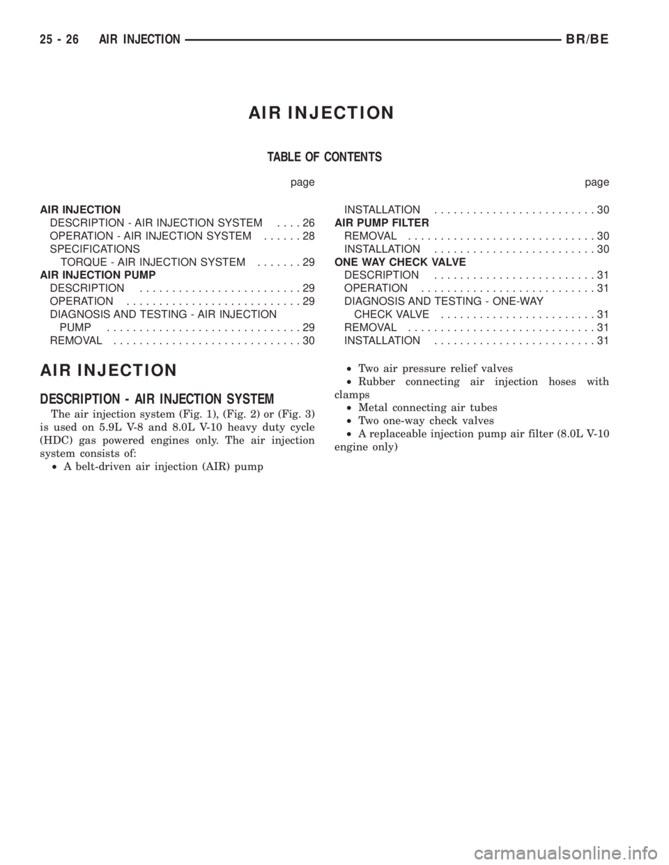
TABLE OF CONTENTS
page page
AIR INJECTION
DESCRIPTION - AIR INJECTION SYSTEM....26
OPERATION - AIR INJECTION SYSTEM......28
SPECIFICATIONS
TORQUE - AIR INJECTION SYSTEM.......29
AIR INJECTION PUMP
DESCRIPTION.........................29
OPERATION...........................29
DIAGNOSIS AND TESTING - AIR INJECTION
PUMP..............................29
REMOVAL.............................30INSTALLATION.........................30
AIR PUMP FILTER
REMOVAL.............................30
INSTALLATION.........................30
ONE WAY CHECK VALVE
DESCRIPTION.........................31
OPERATION...........................31
DIAGNOSIS AND TESTING - ONE-WAY
CHECK VALVE........................31
REMOVAL.............................31
INSTALLATION.........................31
AIR INJECTION
DESCRIPTION - AIR INJECTION SYSTEM
The air injection system (Fig. 1), (Fig. 2) or (Fig. 3)
is used on 5.9L V-8 and 8.0L V-10 heavy duty cycle
(HDC) gas powered engines only. The air injection
system consists of:
²A belt-driven air injection (AIR) pump²Two air pressure relief valves
²Rubber connecting air injection hoses with
clamps
²Metal connecting air tubes
²Two one-way check valves
²A replaceable injection pump air filter (8.0L V-10
engine only)
25 - 26 AIR INJECTIONBR/BE
Page 2208 of 2255
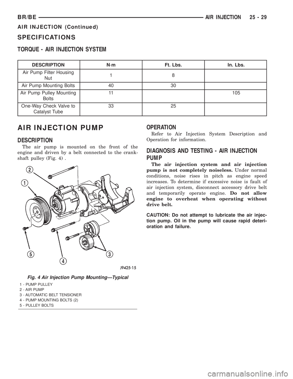
SPECIFICATIONS
TORQUE - AIR INJECTION SYSTEM
DESCRIPTION N´m Ft. Lbs. In. Lbs.
Air Pump Filter Housing
Nut18
Air Pump Mounting Bolts 40 30
Air Pump Pulley Mounting
Bolts11 105
One-Way Check Valve to
Catalyst Tube33 25
AIR INJECTION PUMP
DESCRIPTION
The air pump is mounted on the front of the
engine and driven by a belt connected to the crank-
shaft pulley (Fig. 4) .
OPERATION
Refer to Air Injection System Description and
Operation for information.
DIAGNOSIS AND TESTING - AIR INJECTION
PUMP
The air injection system and air injection
pump is not completely noiseless.Under normal
conditions, noise rises in pitch as engine speed
increases. To determine if excessive noise is fault of
air injection system, disconnect accessory drive belt
and temporarily operate engine.Do not allow
engine to overheat when operating without
drive belt.
CAUTION: Do not attempt to lubricate the air injec-
tion pump. Oil in the pump will cause rapid deteri-
oration and failure.
Fig. 4 Air Injection Pump MountingÐTypical
1 - PUMP PULLEY
2 - AIR PUMP
3 - AUTOMATIC BELT TENSIONER
4 - PUMP MOUNTING BOLTS (2)
5 - PULLEY BOLTS
BR/BEAIR INJECTION 25 - 29
AIR INJECTION (Continued)