2002 DODGE RAM torque
[x] Cancel search: torquePage 1781 of 2255
sludge and/or debris. The torque converter should
also be replaced at the same time.
Failure to flush the cooler and lines will result in
recontamination. Flushing applies to auxiliary cool-
ers as well. The torque converter should also be
replaced whenever a failure generates sludge and
debris. This is necessary because normal converter
flushing procedures will not remove all contami-
nants.
STANDARD PROCEDURE
STANDARD PROCEDURE - FLUID LEVEL
CHECK
Low fluid level can cause a variety of conditions
because it allows the pump to take in air along with
the fluid. As in any hydraulic system, air bubbles
make the fluid spongy, therefore, pressures will be
low and build up slowly.
Improper filling can also raise the fluid level too
high. When the transmssion has too much fluid, the
geartrain churns up foam and cause the same condi-
tions which occur with a low fluid level.
In either case, air bubbles can cause overheating
and/or fluid oxidation, and varnishing. This can
interfere with normal valve, clutch, and accumulator
operation. Foaming can also result in fluid escaping
from the transmission vent where it may be mis-
taken for a leak.
Along with fluid level, it is important to check the
condition of the fluid. When the fluid smells burned,
and is contaminated with metal or friction material
particles, a complete transmission recondition is
needed. Be sure to examine the fluid on the dipstick
closely. If there is any doubt about its condition,
drain out a sample for a double check.
After the fluid has been checked, seat the dipstick
fully to seal out water and dirt.
The transmission has a dipstick to check oil level.
It is located on the right side of the engine. Be sure
to wipe all dirt from dipstick handle before removing.
Fluid level is checked with the engine running at
curb idle speed, the transmission in NEUTRAL and
the transmission fluid at normal operating tempera-
ture.The engine should be running at idle
speed for at least one minute, with the vehicle
on level ground.
The transmission fluid level can be checked two
ways.
PROCEDURE ONE
(1) Transmission fluid must be at normal operat-
ing temperature for accurate fluid level check. Drive
vehicle if necessary to bring fluid temperature up to
normal hot operating temperature of 82ÉC (180ÉF).(2) Position vehicle on level surface.
(3) Start and run engine at curb idle speed.
(4) Apply parking brakes.
(5) Shift transmission momentarily into all gear
ranges. Then shift transmission back to NEUTRAL.
(6) Clean top of filler tube and dipstick to keep
dirt from entering tube.
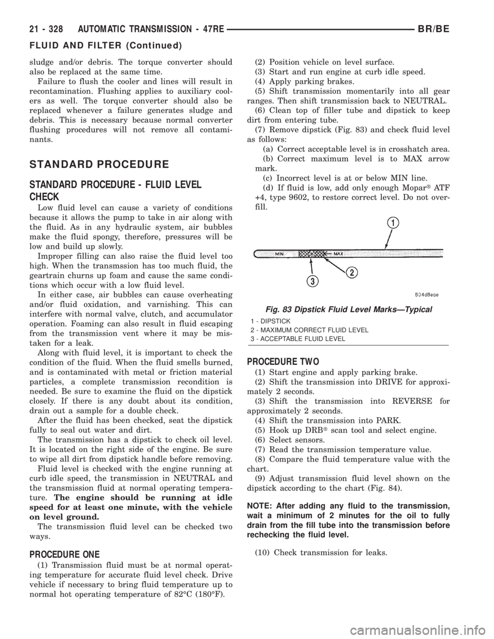
(7) Remove dipstick (Fig. 83) and check fluid level
as follows:
(a) Correct acceptable level is in crosshatch area.
(b) Correct maximum level is to MAX arrow
mark.
(c) Incorrect level is at or below MIN line.
(d) If fluid is low, add only enough MopartAT F
+4, type 9602, to restore correct level. Do not over-
fill.
PROCEDURE TWO
(1) Start engine and apply parking brake.
(2) Shift the transmission into DRIVE for approxi-
mately 2 seconds.
(3) Shift the transmission into REVERSE for
approximately 2 seconds.
(4) Shift the transmission into PARK.
(5) Hook up DRBtscan tool and select engine.
(6) Select sensors.
(7) Read the transmission temperature value.
(8) Compare the fluid temperature value with the
chart.
(9) Adjust transmission fluid level shown on the
dipstick according to the chart (Fig. 84).
NOTE: After adding any fluid to the transmission,
wait a minimum of 2 minutes for the oil to fully
drain from the fill tube into the transmission before
rechecking the fluid level.
(10) Check transmission for leaks.
Fig. 83 Dipstick Fluid Level MarksÐTypical
1 - DIPSTICK
2 - MAXIMUM CORRECT FLUID LEVEL
3 - ACCEPTABLE FLUID LEVEL
21 - 328 AUTOMATIC TRANSMISSION - 47REBR/BE
FLUID AND FILTER (Continued)
Page 1783 of 2255
INSTALLATION
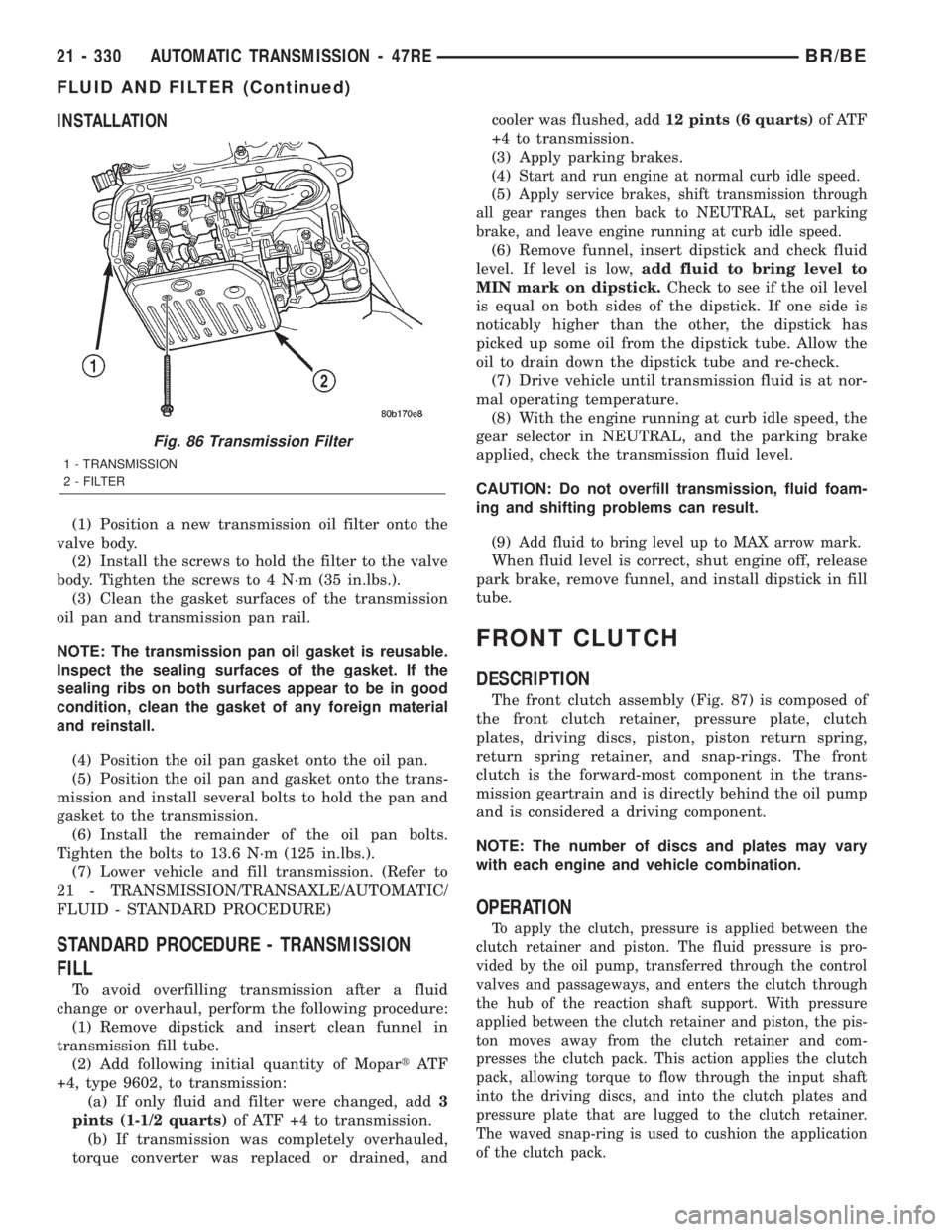
(1) Position a new transmission oil filter onto the
valve body.
(2) Install the screws to hold the filter to the valve
body. Tighten the screws to 4 N´m (35 in.lbs.).
(3) Clean the gasket surfaces of the transmission
oil pan and transmission pan rail.
NOTE: The transmission pan oil gasket is reusable.
Inspect the sealing surfaces of the gasket. If the
sealing ribs on both surfaces appear to be in good
condition, clean the gasket of any foreign material
and reinstall.
(4) Position the oil pan gasket onto the oil pan.
(5) Position the oil pan and gasket onto the trans-
mission and install several bolts to hold the pan and
gasket to the transmission.
(6) Install the remainder of the oil pan bolts.
Tighten the bolts to 13.6 N´m (125 in.lbs.).
(7) Lower vehicle and fill transmission. (Refer to
21 - TRANSMISSION/TRANSAXLE/AUTOMATIC/
FLUID - STANDARD PROCEDURE)
STANDARD PROCEDURE - TRANSMISSION
FILL
To avoid overfilling transmission after a fluid
change or overhaul, perform the following procedure:
(1) Remove dipstick and insert clean funnel in
transmission fill tube.
(2) Add following initial quantity of MopartAT F
+4, type 9602, to transmission:
(a) If only fluid and filter were changed, add3
pints (1-1/2 quarts)of ATF +4 to transmission.
(b) If transmission was completely overhauled,
torque converter was replaced or drained, andcooler was flushed, add12 pints (6 quarts)of ATF
+4 to transmission.
(3) Apply parking brakes.
(4)
Start and run engine at normal curb idle speed.
(5)Apply service brakes, shift transmission through
all gear ranges then back to NEUTRAL, set parking
brake, and leave engine running at curb idle speed.
(6) Remove funnel, insert dipstick and check fluid
level. If level is low,add fluid to bring level to
MIN mark on dipstick.Check to see if the oil level
is equal on both sides of the dipstick. If one side is
noticably higher than the other, the dipstick has
picked up some oil from the dipstick tube. Allow the
oil to drain down the dipstick tube and re-check.
(7) Drive vehicle until transmission fluid is at nor-
mal operating temperature.
(8) With the engine running at curb idle speed, the
gear selector in NEUTRAL, and the parking brake
applied, check the transmission fluid level.
CAUTION: Do not overfill transmission, fluid foam-
ing and shifting problems can result.
(9)
Add fluid to bring level up to MAX arrow mark.
When fluid level is correct, shut engine off, release
park brake, remove funnel, and install dipstick in fill
tube.
FRONT CLUTCH
DESCRIPTION
The front clutch assembly (Fig. 87) is composed of
the front clutch retainer, pressure plate, clutch
plates, driving discs, piston, piston return spring,
return spring retainer, and snap-rings. The front
clutch is the forward-most component in the trans-
mission geartrain and is directly behind the oil pump
and is considered a driving component.
NOTE: The number of discs and plates may vary
with each engine and vehicle combination.
OPERATION
To apply the clutch, pressure is applied between the
clutch retainer and piston. The fluid pressure is pro-
vided by the oil pump, transferred through the control
valves and passageways, and enters the clutch through
the hub of the reaction shaft support. With pressure
applied between the clutch retainer and piston, the pis-
ton moves away from the clutch retainer and com-
presses the clutch pack. This action applies the clutch
pack, allowing torque to flow through the input shaft
into the driving discs, and into the clutch plates and
pressure plate that are lugged to the clutch retainer.
The waved snap-ring is used to cushion the application
of the clutch pack.
Fig. 86 Transmission Filter
1 - TRANSMISSION
2 - FILTER
21 - 330 AUTOMATIC TRANSMISSION - 47REBR/BE
FLUID AND FILTER (Continued)
Page 1789 of 2255
OIL PUMP
DESCRIPTION
The oil pump (Fig. 99) is located in the pump hous-
ing inside the bell housing of the transmission case.
The oil pump consists of an inner and outer gear, a
housing, and a reaction shaft support.
OPERATION
As the torque converter rotates, the converter hub
rotates the inner and outer gears. As the gears
rotate, the clearance between the gear teeth
increases in the crescent area, and creates a suction
at the inlet side of the pump. This suction draws
fluid through the pump inlet from the oil pan. As the
clearance between the gear teeth in the crescent area
decreases, it forces pressurized fluid into the pump
outlet and to the valve body.
STANDARD PROCEDURE - OIL PUMP VOLUME
CHECK
Measuring the oil pump output volume will deter-
mine if sufficient oil flow to the transmission oil
cooler exists, and whether or not an internal trans-
mission failure is present.
Verify that the transmission fluid is at the proper
level. Refer to the Fluid Level Check procedure in
this section. If necessary, fill the transmission to the
proper level with MopartATF +4, type 9602, Auto-
matic Transmission Fluid.
(1) Disconnect theTo coolerline at the cooler
inlet and place a collecting container under the dis-
connected line.
CAUTION: With the fluid set at the proper level,
fluid collection should not exceed (1) quart or inter-
nal damage to the transmission may occur.
(2) Run the engineat curb idle speed, with the
shift selector in neutral.
(3) If one quart of transmission fluid is collected in
the container in 20 seconds or less, oil pump flow vol-
ume is within acceptable limits. If fluid flow is inter-
mittent, or it takes more than 20 seconds to collect
one quart of fluid, refer to the Hydraulic Pressure
tests in this section for further diagnosis.
(4) Re-connect theTo coolerline to the transmis-
sion cooler inlet.
(5) Refill the transmission to proper level.
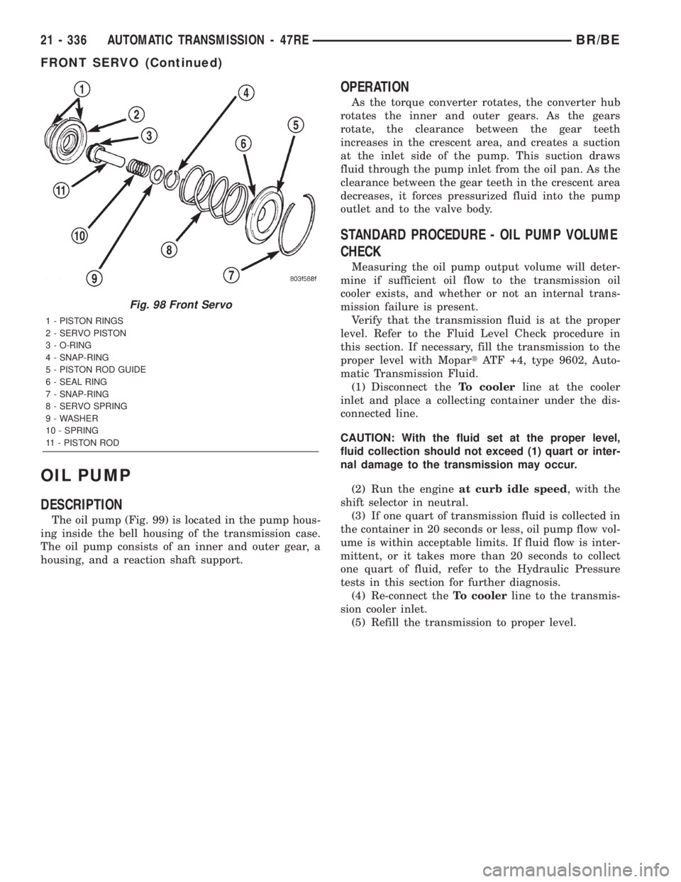
Fig. 98 Front Servo
1 - PISTON RINGS
2 - SERVO PISTON
3 - O-RING
4 - SNAP-RING
5 - PISTON ROD GUIDE
6 - SEAL RING
7 - SNAP-RING
8 - SERVO SPRING
9 - WASHER
10 - SPRING
11 - PISTON ROD
21 - 336 AUTOMATIC TRANSMISSION - 47REBR/BE
FRONT SERVO (Continued)
Page 1795 of 2255
CAUTION: The reaction shaft support seal rings will
break if overspread, or twisted. If new rings are
being installed, spread them only enough for instal-
lation. Also be very sure the ring ends are securely
hooked together after installation. Otherwise, the
rings will either prevent pump installation, or break
during installation.
(4) Align and install reaction shaft support on
pump body.
(5) Install bolts attaching reaction shaft support to
pump. Tighten bolts to 20 N´m (175 in. lbs.) torque.
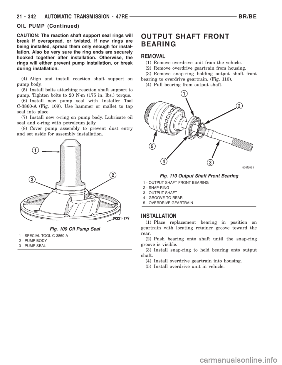
(6) Install new pump seal with Installer Tool
C-3860-A (Fig. 109). Use hammer or mallet to tap
seal into place.
(7) Install new o-ring on pump body. Lubricate oil
seal and o-ring with petroleum jelly.
(8) Cover pump assembly to prevent dust entry
and set aside for assembly installation.OUTPUT SHAFT FRONT
BEARING
REMOVAL
(1) Remove overdrive unit from the vehicle.
(2) Remove overdrive geartrain from housing.
(3) Remove snap-ring holding output shaft front
bearing to overdrive geartrain. (Fig. 110).
(4) Pull bearing from output shaft.
INSTALLATION
(1) Place replacement bearing in position on
geartrain with locating retainer groove toward the
rear.
(2) Push bearing onto shaft until the snap-ring
groove is visible.
(3) Install snap-ring to hold bearing onto output
shaft.
(4) Install overdrive geartrain into housing.
(5) Install overdrive unit in vehicle.
Fig. 109 Oil Pump Seal
1 - SPECIAL TOOL C-3860-A
2 - PUMP BODY
3 - PUMP SEAL
Fig. 110 Output Shaft Front Bearing
1 - OUTPUT SHAFT FRONT BEARING
2 - SNAP-RING
3 - OUTPUT SHAFT
4 - GROOVE TO REAR
5 - OVERDRIVE GEARTRAIN
21 - 342 AUTOMATIC TRANSMISSION - 47REBR/BE
OIL PUMP (Continued)
Page 1796 of 2255
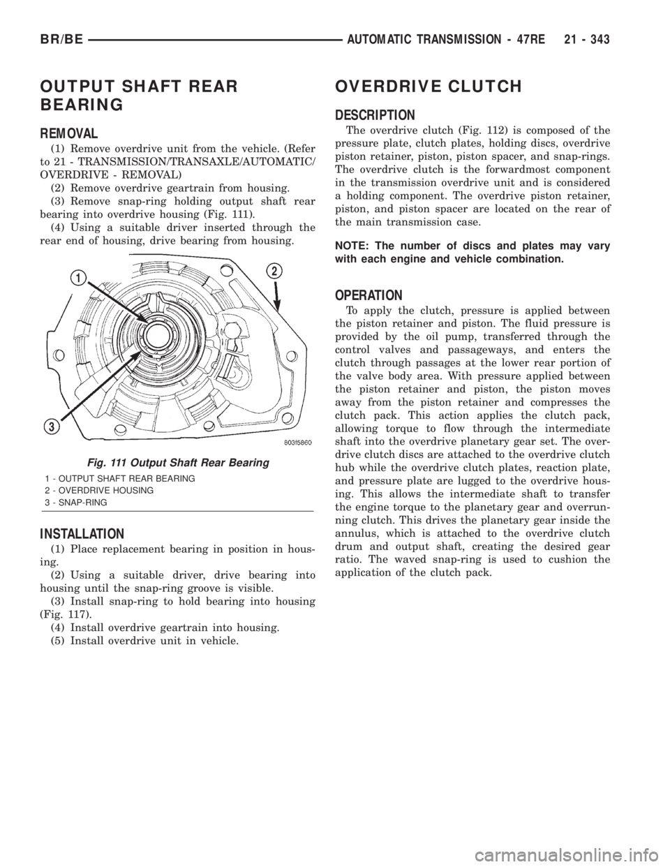
OUTPUT SHAFT REAR
BEARING
REMOVAL
(1) Remove overdrive unit from the vehicle. (Refer
to 21 - TRANSMISSION/TRANSAXLE/AUTOMATIC/
OVERDRIVE - REMOVAL)
(2) Remove overdrive geartrain from housing.
(3) Remove snap-ring holding output shaft rear
bearing into overdrive housing (Fig. 111).
(4) Using a suitable driver inserted through the
rear end of housing, drive bearing from housing.
INSTALLATION
(1) Place replacement bearing in position in hous-
ing.
(2) Using a suitable driver, drive bearing into
housing until the snap-ring groove is visible.
(3) Install snap-ring to hold bearing into housing
(Fig. 117).
(4) Install overdrive geartrain into housing.
(5) Install overdrive unit in vehicle.
OVERDRIVE CLUTCH
DESCRIPTION
The overdrive clutch (Fig. 112) is composed of the
pressure plate, clutch plates, holding discs, overdrive
piston retainer, piston, piston spacer, and snap-rings.
The overdrive clutch is the forwardmost component
in the transmission overdrive unit and is considered
a holding component. The overdrive piston retainer,
piston, and piston spacer are located on the rear of
the main transmission case.
NOTE: The number of discs and plates may vary
with each engine and vehicle combination.
OPERATION
To apply the clutch, pressure is applied between
the piston retainer and piston. The fluid pressure is
provided by the oil pump, transferred through the
control valves and passageways, and enters the
clutch through passages at the lower rear portion of
the valve body area. With pressure applied between
the piston retainer and piston, the piston moves
away from the piston retainer and compresses the
clutch pack. This action applies the clutch pack,
allowing torque to flow through the intermediate
shaft into the overdrive planetary gear set. The over-
drive clutch discs are attached to the overdrive clutch
hub while the overdrive clutch plates, reaction plate,
and pressure plate are lugged to the overdrive hous-
ing. This allows the intermediate shaft to transfer
the engine torque to the planetary gear and overrun-
ning clutch. This drives the planetary gear inside the
annulus, which is attached to the overdrive clutch
drum and output shaft, creating the desired gear
ratio. The waved snap-ring is used to cushion the
application of the clutch pack.
Fig. 111 Output Shaft Rear Bearing
1 - OUTPUT SHAFT REAR BEARING
2 - OVERDRIVE HOUSING
3 - SNAP-RING
BR/BEAUTOMATIC TRANSMISSION - 47RE 21 - 343
Page 1812 of 2255
GEAR CASE
(1) Position park pawl and spring in case and
install park pawl shaft. Verify that end of spring
with 90É bend is hooked to pawl and straight end of
spring is seated against case.
(2) Install pawl shaft retaining bolt. Tighten bolt
to 27 N´m (20 ft. lbs.) torque.
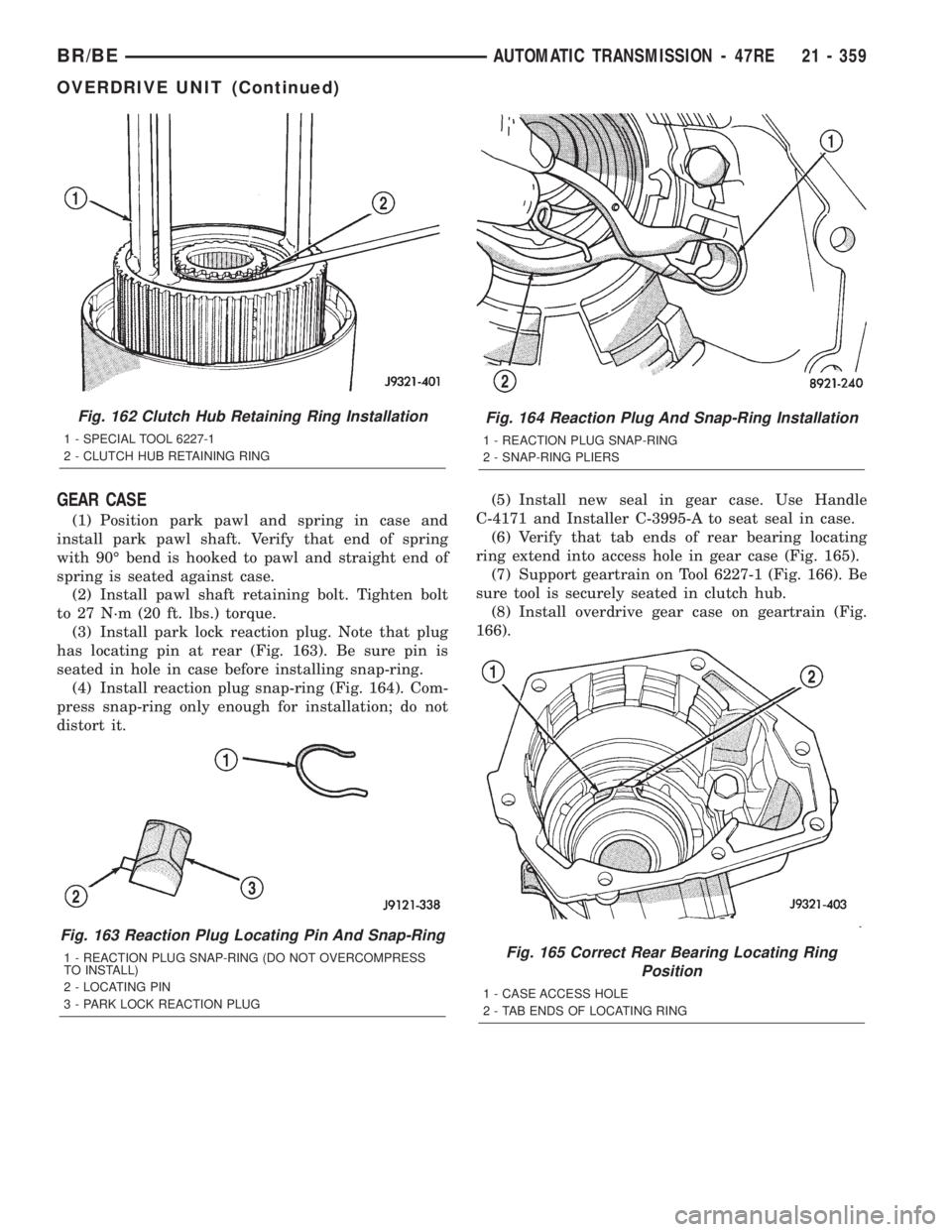
(3) Install park lock reaction plug. Note that plug
has locating pin at rear (Fig. 163). Be sure pin is
seated in hole in case before installing snap-ring.
(4) Install reaction plug snap-ring (Fig. 164). Com-
press snap-ring only enough for installation; do not
distort it.(5) Install new seal in gear case. Use Handle
C-4171 and Installer C-3995-A to seat seal in case.
(6) Verify that tab ends of rear bearing locating
ring extend into access hole in gear case (Fig. 165).
(7) Support geartrain on Tool 6227-1 (Fig. 166). Be
sure tool is securely seated in clutch hub.
(8) Install overdrive gear case on geartrain (Fig.
166).
Fig. 162 Clutch Hub Retaining Ring Installation
1 - SPECIAL TOOL 6227-1
2 - CLUTCH HUB RETAINING RING
Fig. 163 Reaction Plug Locating Pin And Snap-Ring
1 - REACTION PLUG SNAP-RING (DO NOT OVERCOMPRESS
TO INSTALL)
2 - LOCATING PIN
3 - PARK LOCK REACTION PLUG
Fig. 164 Reaction Plug And Snap-Ring Installation
1 - REACTION PLUG SNAP-RING
2 - SNAP-RING PLIERS
Fig. 165 Correct Rear Bearing Locating Ring
Position
1 - CASE ACCESS HOLE
2 - TAB ENDS OF LOCATING RING
BR/BEAUTOMATIC TRANSMISSION - 47RE 21 - 359
OVERDRIVE UNIT (Continued)
Page 1818 of 2255
(11) Remove piston retainer from case. Cover
retainer with plastic sheeting, or paper to keep it
dust free.
(12) Clean case and cam thoroughly. Be sure any
chips/shavings generated during cam installation are
removed from case.
(13) Install new gasket at rear of transmission
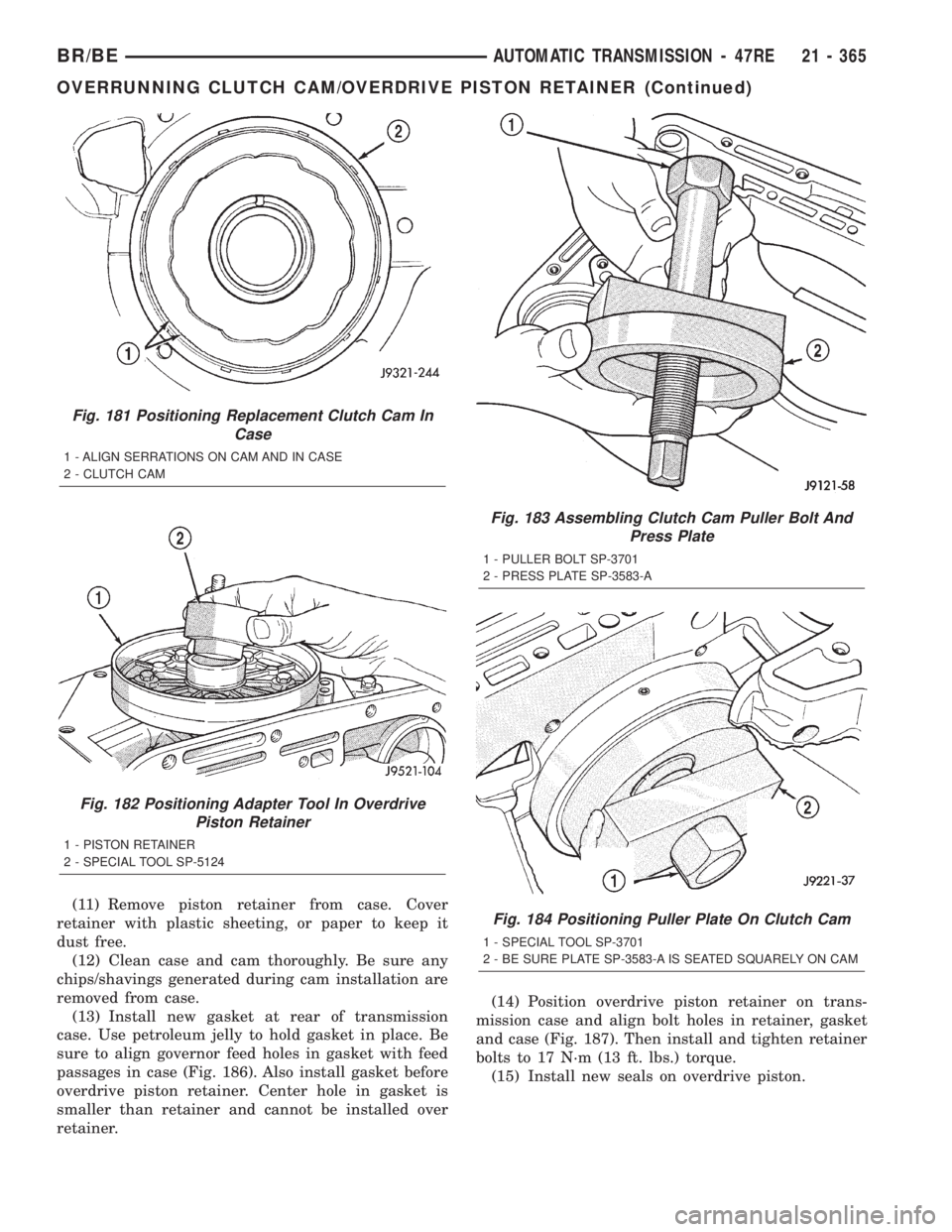
case. Use petroleum jelly to hold gasket in place. Be
sure to align governor feed holes in gasket with feed
passages in case (Fig. 186). Also install gasket before
overdrive piston retainer. Center hole in gasket is
smaller than retainer and cannot be installed over
retainer.(14) Position overdrive piston retainer on trans-
mission case and align bolt holes in retainer, gasket
and case (Fig. 187). Then install and tighten retainer
bolts to 17 N´m (13 ft. lbs.) torque.
(15) Install new seals on overdrive piston.
Fig. 181 Positioning Replacement Clutch Cam In
Case
1 - ALIGN SERRATIONS ON CAM AND IN CASE
2 - CLUTCH CAM
Fig. 182 Positioning Adapter Tool In Overdrive
Piston Retainer
1 - PISTON RETAINER
2 - SPECIAL TOOL SP-5124
Fig. 183 Assembling Clutch Cam Puller Bolt And
Press Plate
1 - PULLER BOLT SP-3701
2 - PRESS PLATE SP-3583-A
Fig. 184 Positioning Puller Plate On Clutch Cam
1 - SPECIAL TOOL SP-3701
2 - BE SURE PLATE SP-3583-A IS SEATED SQUARELY ON CAM
BR/BEAUTOMATIC TRANSMISSION - 47RE 21 - 365
OVERRUNNING CLUTCH CAM/OVERDRIVE PISTON RETAINER (Continued)
Page 1820 of 2255
PARK/NEUTRAL POSITION
SWITCH
DIAGNOSIS AND TESTING - PARK/NEUTRAL
POSITION SWITCH
The center terminal of the park/neutral position
switch is the starter-circuit terminal. It provides the
ground for the starter solenoid circuit through the
selector lever in PARK and NEUTRAL positions only.
The outer terminals on the switch are for the backup
lamp circuit.
SWITCH TEST
To test the switch, remove the wiring connector.
Test for continuity between the center terminal and
the transmission case. Continuity should exist only
when the transmission is in PARK or NEUTRAL.
Shift the transmission into REVERSE and test
continuity at the switch outer terminals. Continuity
should exist only when the transmission is in
REVERSE. Continuity should not exist between the
outer terminals and the case.
Check gearshift linkage adjustment before replac-
ing a switch that tests faulty.
REMOVAL
(1) Raise vehicle and position drain pan under
switch.
(2) Disconnect switch wires.
(3) Remove switch from case.
INSTALLATION
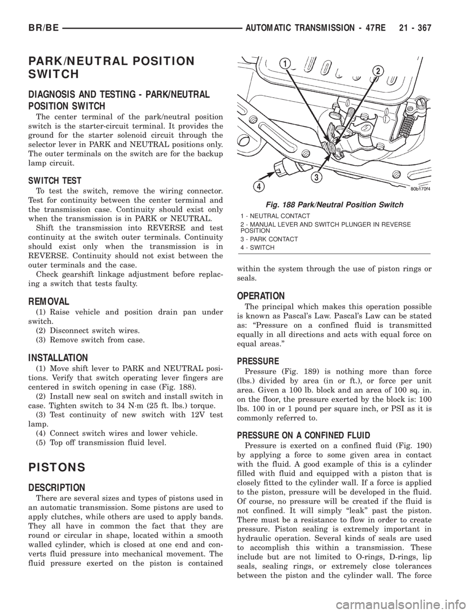
(1) Move shift lever to PARK and NEUTRAL posi-
tions. Verify that switch operating lever fingers are
centered in switch opening in case (Fig. 188).
(2) Install new seal on switch and install switch in
case. Tighten switch to 34 N´m (25 ft. lbs.) torque.
(3) Test continuity of new switch with 12V test
lamp.
(4) Connect switch wires and lower vehicle.
(5) Top off transmission fluid level.
PISTONS
DESCRIPTION
There are several sizes and types of pistons used in
an automatic transmission. Some pistons are used to
apply clutches, while others are used to apply bands.
They all have in common the fact that they are
round or circular in shape, located within a smooth
walled cylinder, which is closed at one end and con-
verts fluid pressure into mechanical movement. The
fluid pressure exerted on the piston is containedwithin the system through the use of piston rings or
seals.
OPERATION
The principal which makes this operation possible
is known as Pascal's Law. Pascal's Law can be stated
as: ªPressure on a confined fluid is transmitted
equally in all directions and acts with equal force on
equal areas.º
PRESSURE
Pressure (Fig. 189) is nothing more than force
(lbs.) divided by area (in or ft.), or force per unit
area. Given a 100 lb. block and an area of 100 sq. in.
on the floor, the pressure exerted by the block is: 100
lbs. 100 in or 1 pound per square inch, or PSI as it is
commonly referred to.
PRESSURE ON A CONFINED FLUID
Pressure is exerted on a confined fluid (Fig. 190)
by applying a force to some given area in contact
with the fluid. A good example of this is a cylinder
filled with fluid and equipped with a piston that is
closely fitted to the cylinder wall. If a force is applied
to the piston, pressure will be developed in the fluid.
Of course, no pressure will be created if the fluid is
not confined. It will simply ªleakº past the piston.
There must be a resistance to flow in order to create
pressure. Piston sealing is extremely important in
hydraulic operation. Several kinds of seals are used
to accomplish this within a transmission. These
include but are not limited to O-rings, D-rings, lip
seals, sealing rings, or extremely close tolerances
between the piston and the cylinder wall. The force
Fig. 188 Park/Neutral Position Switch
1 - NEUTRAL CONTACT
2 - MANUAL LEVER AND SWITCH PLUNGER IN REVERSE
POSITION
3 - PARK CONTACT
4 - SWITCH
BR/BEAUTOMATIC TRANSMISSION - 47RE 21 - 367