Page 17 of 110

The steering is locked, and the taillight
and auxiliary light are on, but all other
electrical systems are off. The key can
be removed.
The s")
INSTRUMENT AND CONTROL FUNCTIONS
3-2
3
EAU01590
(Parking)
The steering is locked, and the taillight
and auxiliary light are on, but all other
electrical systems are off. The key can
be removed.
The steering must be locked before the
key can be turned to “ ”.
ECA00043
CAUTION:_ Do not use the parking position for
an extended length of time, other-
wise the battery may discharge. _
EAU03034
Indicator and warning lights
EAU03299
Turn signal indicator lights
“”/“”
The corresponding indicator light flash-
es when the turn signal switch is
pushed to the left or right.
EAU00061
Neutral indicator light “ ”
This indicator light comes on when the
transmission is in the neutral position.
EAU00063
High beam indicator light “ ”
This indicator light comes on when the
high beam of the headlight is switched
on.
EAU01707
Coolant temperature warning light
“”
This warning light comes on when the
engine overheats. When this occurs,
stop the engine immediately and allow
the engine to cool.
The electrical circuit of the warning light
can be checked according to the fol-
lowing procedure.
1. Set the engine stop switch to “ ”
and turn the key to “ON”.
2. Shift the transmission into the neu-
tral position or pull the clutch lever.
3. Push the start switch. If the warn-
ing light does not come on while
pushing the start switch, have a
Yamaha dealer check the electri-
cal circuit.
EC000002
CAUTION:@ Do not operate the engine if it is
overheated. @
1. Left turn signal indicator light “ ”
2. Neutral indicator light “ ”
3. High beam indicator light “ ”
4. Coolant temperature warning light “ ”
5. Right turn signal indicator light “ ”
6. Fuel level warning light “ ”
E_4tx.book Page 2 Wednesday, October 4, 2000 4:28 PM
Page 18 of 110

INSTRUMENT AND CONTROL FUNCTIONS
3-3
3
EAU03680
Fuel level warning light “ ”
This warning light comes on when the
fuel level drops below approximately
3.1 L. When this occurs, refuel as soon
as possible.
The electrical circuit of the warning light
can be checked according to the fol-
lowing procedure.
1. Set the engine stop switch to “ ”
and turn the key to “ON”.
2. Shift the transmission into the neu-
tral position or pull the clutch lever.
3. Push the start switch. If the warn-
ing light does not come on, have a
Yamaha dealer check the electri-
cal circuit.
EAU03492
Speedometer unit The speedometer unit is equipped with
the following:l
a speedometer (which shows the
riding speed)
l
an odometer (which shows the to-
tal distance traveled)
l
two tripmeters (which show the
distance traveled since they were
last set to zero)
l
a clockOdometer and tripmeter modes
Pushing the “SELECT” button switches
the display between the odometer
mode “ODO” and the tripmeter modes
“TRIP 1”, “TRIP 2” and “CLOCK” in the
following order:
ODO
®TRIP 1
®TRIP 2
®CLOCK
®
ODO
To reset a tripmeter, select it by push-
ing the “SELECT” button, and then
push the “RESET” button for at least
one second. The tripmeters can be
used to estimate the distance that can
be traveled with a full tank of fuel. This
information will enable you to plan fu-
ture fuel stops.
Clock mode
To change the display to the clock
mode, push both the “SELECT” and
“RESET” buttons.
To change the display back to the
odometer mode, push the “SELECT”
button.
1. Speedometer
2. Odometer/tripmeter/clock
3. “SELECT” button
4. “RESET” button
E_4tx.book Page 3 Wednesday, October 4, 2000 4:28 PM
Page 19 of 110

INSTRUMENT AND CONTROL FUNCTIONS
3-4
3 To set the clock
1. Push both the “SELECT” and
“RESET” buttons for at least two
seconds.
2. When the hour digits start flashing,
push the “RESET” button to set
the hours.
3. Push the “SELECT” button to
change the minutes.
4. When the minute digits start flash-
ing, push the “RESET” button to
set the minutes.
5. Push the “SELECT” button to start
the clock.NOTE:@ After setting the clock, be sure to push
the “SELECT” button before turning the
key to “OFF”, otherwise the clock will
not be set. @
EAU00101
Tachometer The electric tachometer allows the rider
to monitor the engine speed and keep it
within the ideal power range.
EC000003
CAUTION:@ Do not operate the engine in the ta-
chometer red zone.
Red zone: 8,000 r/min and above @
EAU00103
Self-diagnosis device This model is equipped with a self-di-
agnosis device for the throttle position
sensor circuit.
If the throttle position sensor circuit is
defective, the tachometer will repeat-
edly display the following error code:CB-10EIf the tachometer displays such an er-
ror code, have a Yamaha dealer check
the motorcycle.
EC000004
CAUTION:@ When the tachometer displays an
error code, the motorcycle should
be checked as soon as possible in
order to avoid engine damage. @
1. Tachometer
2. Tachometer red zone
0 r/min for
3 seconds
3,000 r/min
for 2.5 sec-
onds
Current engine
speed for
3 seconds
E_4tx.book Page 4 Wednesday, October 4, 2000 4:28 PM
Page 20 of 110
INSTRUMENT AND CONTROL FUNCTIONS
3-5
3
EAU00109
Anti-theft alarm (optional) This motorcycle can be equipped with
an optional anti-theft alarm by a
Yamaha dealer. Contact a Yamaha
dealer for more information.
EAU00110
Fuel gauge The fuel gauge indicates the amount of
fuel in the fuel tank. The needle moves
towards “E” (Empty) as the fuel level
decreases. When the needle reaches
“E”, approximately 3.1 L of fuel remain
in the fuel tank. If this occurs, refuel as
soon as possible.NOTE:@ Do not allow the fuel tank to empty it-
self completely. @
EAU00118
Handlebar switches
EAU00120
Pass switch “PASS”
Press this switch to flash the headlight.
EAU00121
Dimmer switch
Set this switch to “ ” for the high
beam and to “ ” for the low beam.
1. Fuel gauge
1. Pass switch “PASS”
2. Dimmer switch
3. Turn signal switch
4. Horn switch “ ”
5. Hazard switch “ ”
E_4tx.book Page 5 Wednesday, October 4, 2000 4:28 PM
Page 21 of 110

INSTRUMENT AND CONTROL FUNCTIONS
3-6
3
EAU00127
Turn signal switch
To signal a right-hand turn, push this
switch to “ ”. To signal a left-hand
turn, push this switch to “ ”. When
released, the switch returns to the cen-
ter position. To cancel the turn signal
lights, push the switch in after it has re-
turned to the center position.
EAU00129
Horn switch “ ”
Press this switch to sound the horn.
EAU03826
Hazard switch “ ”
With the key in the “ON” or “ ” posi-
tion, use this switch to turn on the haz-
ard light (simultaneous flashing of all
turn signal lights).
The hazard light is used in case of an
emergency or to warn other drivers
when your motorcycle is stopped
where it might be a traffic hazard.
EC000006
CAUTION:_ Do not use the hazard light for an ex-
tended length of time, otherwise the
battery may discharge. _
EAU00138
Engine stop switch
Set this switch to “ ” to stop the en-
gine in case of an emergency, such as
when the motorcycle overturns or
when the throttle cable is stuck.
EAU00134
Light switch
Set this switch to “ ” to turn on the
auxiliary light, meter lighting and tail-
light. Set the switch to “ ” to turn on
the headlight also.
EAU00143
Start switch “ ”
Push this switch to crank the engine
with the starter.
EC000005
CAUTION:@ See page 5-1 for starting instruc-
tions prior to starting the engine. @
1. Engine stop switch
2. Light switch
3. Start switch “ ”
E_4tx.book Page 6 Wednesday, October 4, 2000 4:28 PM
Page 22 of 110

INSTRUMENT AND CONTROL FUNCTIONS
3-7
3
EAU00152
Clutch lever The clutch lever is located at the left
handlebar grip. To disengage the
clutch, pull the lever toward the handle-
bar grip. To engage the clutch, release
the lever. The lever should be pulled
rapidly and released slowly for smooth
clutch operation.
The clutch lever is equipped with a
clutch switch, which is part of the igni-
tion circuit cut-off system. (See
page 3-18 for an explanation of the ig-
nition circuit cut-off system.)
EAU00157
Shift pedal The shift pedal is located on the left
side of the engine and is used in com-
bination with the clutch lever when
shifting the gears of the 5-speed con-
stant-mesh transmission equipped on
this motorcycle.
EAU00160
Brake lever The brake lever is located at the right
handlebar grip. To apply the front
brake, pull the lever toward the handle-
bar grip.
1. Clutch lever
1. Shift pedal
1. Brake lever
2. Brake lever position adjusting nut
a. Distance between brake lever and handlebar
grip
E_4tx.book Page 7 Wednesday, October 4, 2000 4:28 PM
Page 23 of 110
INSTRUMENT AND CONTROL FUNCTIONS
3-8
3
The brake lever is equipped with a po-
sition adjusting nut. To adjust the dis-
tance between the brake lever and the
handlebar grip, turn the adjusting nut
while holding the lever pushed away
from the handlebar grip. Make sure that
the mark “ ” on the adjusting nut is
aligned with the mark “ ” on the brake
lever.
EAU00162
Brake pedal The brake pedal is on the right side of
the motorcycle. To apply the rear
brake, press down on the brake pedal.
1. Brake lever position adjusting nut
2. Properly aligned marks
1. Brake pedal
E_4tx.book Page 8 Wednesday, October 4, 2000 4:28 PM
Page 24 of 110

INSTRUMENT AND CONTROL FUNCTIONS
3-9
3
EAU02935
Fuel tank cap To open the fuel tank cap
Open the fuel tank cap lock cover, in-
sert the key into the lock, and then turn
it 1/4 turn clockwise. The lock will be re-
leased and the fuel tank cap can be
opened.
To close the fuel tank cap
1. Push the fuel tank cap into posi-
tion with the key inserted in the
lock. 2. Turn the key counterclockwise to
the original position, remove it,
and then close the lock cover.
NOTE:@ The fuel tank cap cannot be closed un-
less the key is in the lock. In addition,
the key cannot be removed if the cap is
not properly closed and locked. @
EWA00025
WARNING
@ Make sure that the fuel tank cap is
properly closed before riding. @
EAU03753
Fuel Make sure that there is sufficient fuel in
the tank. Fill the fuel tank to the bottom
of the filler tube as shown.
EW000130
WARNING
_ l
Do not overfill the fuel tank, oth-
erwise it may overflow when the
fuel warms up and expands.
l
Avoid spilling fuel on the hot
engine.
_
1. Fuel tank cap lock cover
2. Unlock.
1. Fuel tank filler tube
2. Fuel level
E_4tx.book Page 9 Wednesday, October 4, 2000 4:28 PM
 1
1 2
2 3
3 4
4 5
5 6
6 7
7 8
8 9
9 10
10 11
11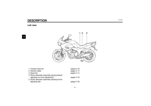 12
12 13
13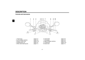 14
14 15
15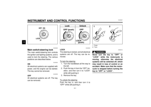 16
16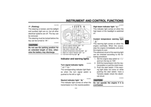 17
17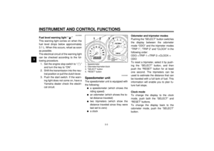 18
18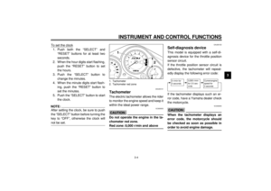 19
19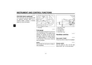 20
20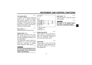 21
21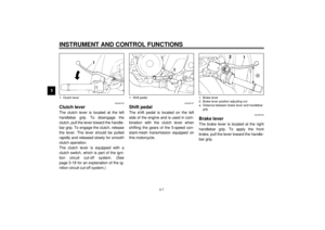 22
22 23
23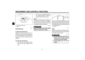 24
24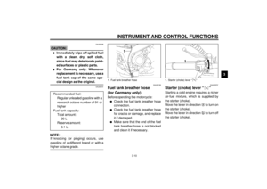 25
25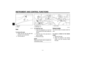 26
26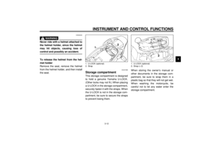 27
27 28
28 29
29 30
30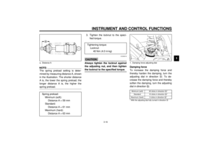 31
31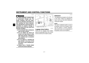 32
32 33
33 34
34 35
35 36
36 37
37 38
38 39
39 40
40 41
41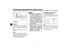 42
42 43
43 44
44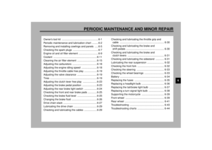 45
45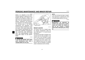 46
46 47
47 48
48 49
49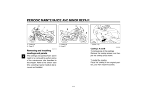 50
50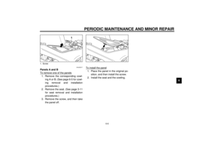 51
51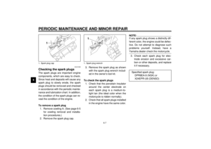 52
52 53
53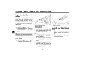 54
54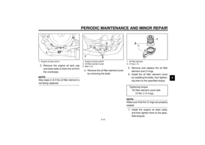 55
55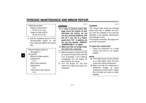 56
56 57
57 58
58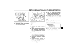 59
59 60
60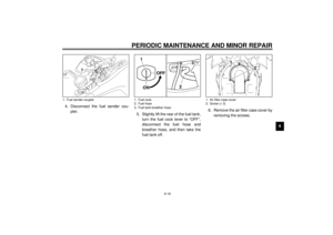 61
61 62
62 63
63 64
64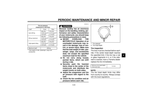 65
65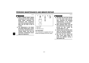 66
66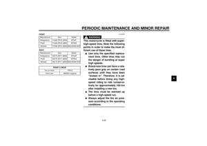 67
67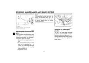 68
68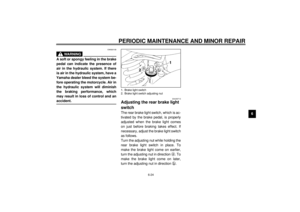 69
69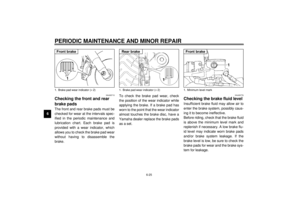 70
70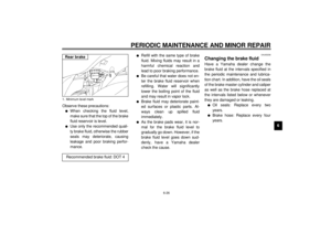 71
71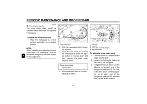 72
72 73
73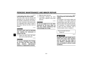 74
74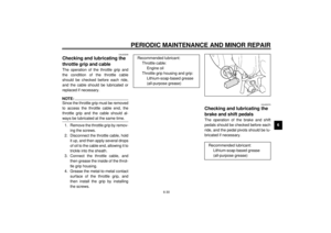 75
75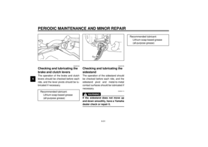 76
76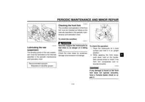 77
77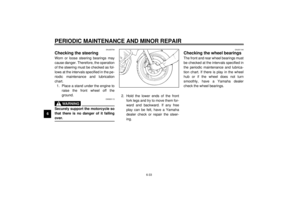 78
78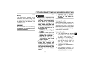 79
79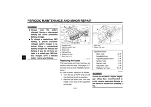 80
80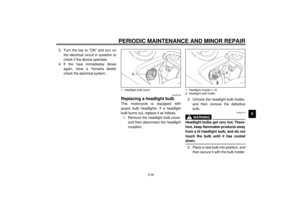 81
81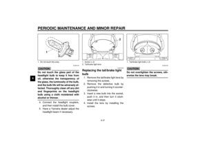 82
82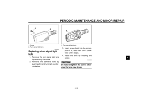 83
83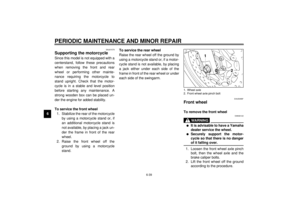 84
84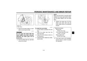 85
85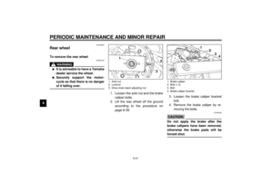 86
86 87
87 88
88 89
89 90
90 91
91 92
92 93
93 94
94 95
95 96
96 97
97 98
98 99
99 100
100 101
101 102
102 103
103 104
104 105
105 106
106 107
107 108
108 109
109 This motorcycle can be equipped with
an optional anti-theft alarm by a
Yamaha dealer. Contact a Yamaha
dealer for more infor")
