Page 57 of 110

PERIODIC MAINTENANCE AND MINOR REPAIR
6-12
6 2. Check the coolant level in the
coolant reservoir.
NOTE:@ The coolant should be between the
minimum and maximum level marks. @
3. If the coolant is at or below the
minimum level mark, remove the
seat (See page 3-11 for seat re-
moval and installation proce-
dures.), and then open the coolant
reservoir cap.
4. Add coolant or distilled water to
raise the coolant to the specified
level, close the coolant reservoir
cap, and then install the seat.
EC000080
CAUTION:l
If coolant is not available, use
distilled water or soft tap water
instead. Do not use hard water
or salt water since it is harmful
to the engine.
l
If water has been used instead
of coolant, replace it with cool-
ant as soon as possible, other-
wise the engine may not be
sufficiently cooled and the cool-
ing system will not be protected
against frost and corrosion.
l
If water has been added to the
coolant, have a Yamaha dealer
check the antifreeze content of
the coolant as soon as possible,
otherwise the effectiveness of
the coolant will be reduced.
EW000067
WARNING
Never attempt to remove the radia-
tor cap when the engine is hot.
1. Coolant reservoir
2. Maximum level mark
3. Minimum level mark
1. Coolant reservoir capCoolant reservoir capacity:
0.3 L
E_4tx.book Page 12 Wednesday, October 4, 2000 4:28 PM
Page 58 of 110
PERIODIC MAINTENANCE AND MINOR REPAIR
6-13
6
NOTE:@ l
The radiator fan is automatically
switched on or off according to the
coolant temperature in the radia-
tor.
l
If the engine overheats, see page
6-45 for further instructions.
@
EAU03300
To change the coolant
1. Place the motorcycle on a level
surface and let the engine cool if
necessary.
2. Remove the seat. (See page 3-11
for seat removal and installation
procedures.)
3. Remove cowling B and panel B.
(See pages 6-5 and 6-6 for cowl-
ing and panel removal and instal-
lation procedures.)
4. Place a container under the en-
gine to collect the used coolant.5. Remove the radiator cap retaining
bolt and the radiator cap.
EW000067
WARNING
@ Never attempt to remove the radia-
tor cap when the engine is hot. @1. Radiator cap retaining bolt
2. Radiator cap
E_4tx.book Page 13 Wednesday, October 4, 2000 4:28 PM
Page 59 of 110

PERIODIC MAINTENANCE AND MINOR REPAIR
6-14
6 6. Remove the coolant drain bolts to
drain the cooling system.
7. Remove the coolant reservoir
bolts.
8. Slightly move the coolant reservoir
back, and then disconnect the
hose at the bottom of the coolant
reservoir.
9. Drain the coolant from the coolant
reservoir by opening the cap, then
turning the reservoir upside down.
10. Connect the hose to the coolant
reservoir.
11. Install the coolant reservoir by
placing it in the original position,
then installing the bolts.12. After the coolant is completely
drained, thoroughly flush the cool-
ing system with clean tap water.
13. Install the coolant drain bolts, and
then tighten them to the specified
torque.
NOTE:@ Check the washers for damage and re-
place them if necessary. @14. Pour the recommended coolant
into the radiator until it is full.
1. Coolant drain bolt (´ 2)
1. Coolant reservoir
2. Bolt (´ 2)
3. Clamp
4. Hose
Tightening torque:
Coolant drain bolt:
7 Nm (0.7 m·kg)
E_4tx.book Page 14 Wednesday, October 4, 2000 4:28 PM
Page 60 of 110

PERIODIC MAINTENANCE AND MINOR REPAIR
6-15
6
EC000080
CAUTION:@ l
If coolant is not available, use
distilled water or soft tap water
instead. Do not use hard water
or salt water since it is harmful
to the engine.
l
If water has been used instead
of coolant, replace it with cool-
ant as soon as possible, other-
wise the engine may not be
sufficiently cooled and the cool-
ing system will not be protected
against frost and corrosion.
l
If water has been added to the
coolant, have a Yamaha dealer
check the antifreeze content of
the coolant as soon as possible,
otherwise the effectiveness of
the coolant will be reduced.
@15. Install the radiator cap, start the
engine, let it idle for several min-
utes, and then turn it off.
16. Remove the radiator cap to check
the coolant level in the radiator. If
necessary, add sufficient coolant
until it reaches the top of the radia-
tor, and then install the radiator
cap and the cap retaining bolt.
17. Check the coolant level in the res-
ervoir. If necessary, remove the
coolant reservoir cap, add coolant
to the maximum level mark, and
then install the cap.
18. Install the panel, the cowling, and
the seat.
19. Start the engine, and then check
the vehicle for coolant leakage. If
coolant is leaking, have a Yamaha
dealer check the cooling system.
EAU03496
Cleaning the air filter element The air filter element should be cleaned
at the intervals specified in the periodic
maintenance and lubrication chart.
Clean the air filter element more fre-
quently if you are riding in unusually
wet or dusty areas.
1. Remove the seat. (See page 3-11
for seat removal and installation
procedures.)
2. Remove cowlings A and B as well
as panels A and B. (See pages 6-5
and 6-6 for cowling and panel re-
moval and installation proce-
dures.)
3. Remove the fuel tank bolts. Antifreeze/water mixture ratio:
1:1
Recommended antifreeze:
High-quality ethylene glycol
antifreeze containing corrosion
inhibitors for aluminum engines
Coolant quantity:
Total amount:
1.7 L
Coolant reservoir capacity:
0.3 L1. Bolt (´ 3)
E_4tx.book Page 15 Wednesday, October 4, 2000 4:28 PM
Page 61 of 110
PERIODIC MAINTENANCE AND MINOR REPAIR
6-16
6 4. Disconnect the fuel sender cou-
pler.
5. Slightly lift the rear of the fuel tank,
turn the fuel cock lever to “OFF”,
disconnect the fuel hose and
breather hose, and then take the
fuel tank off.6. Remove the air filter case cover by
removing the screws.
1. Fuel sender coupler
1. Fuel cock
2. Fuel hose
3. Fuel tank breather hose
1. Air filter case cover
2. Screw (´ 3)
E_4tx.book Page 16 Wednesday, October 4, 2000 4:28 PM
Page 62 of 110

PERIODIC MAINTENANCE AND MINOR REPAIR
6-17
67. Pull the air filter element out. 8. Lightly tap the air filter element to
remove most of the dust and dirt,
and then blow the remaining dirt
out with compressed air as shown.
If the air filter element is damaged,
replace it.
9. Insert the air filter element into the
air filter case.
EC000082
CAUTION:@ l
Make sure that the air filter ele-
ment is properly seated in the
air filter case.
l
The engine should never be op-
erated without the air filter ele-
ment installed, otherwise the
piston(s) and/or cylinder(s) may
become excessively worn.
@10. Install the air filter case cover by
installing the screws.
11. Connect the fuel hose, breather
hose and fuel sender coupler, turn
the fuel cock lever to “ON”, and
then install the fuel tank by install-
ing the bolts.
EWA00013
WARNING
@ Make sure that the fuel hose and
breather hose are properly connect-
ed and routed, and not pinched. Re-
place any damaged hoses. @12. Install the panels and cowlings.
13. Install the seat.
1. Air filter elementE_4tx.book Page 17 Wednesday, October 4, 2000 4:28 PM
Page 63 of 110

PERIODIC MAINTENANCE AND MINOR REPAIR
6-18
6
EAU00630
Adjusting the carburetors The carburetors are important parts of
the engine and require very sophisti-
cated adjustment. Therefore, most car-
buretor adjustments should be left to a
Yamaha dealer, who has the neces-
sary professional knowledge and expe-
rience. The adjustment described in
the following section, however, may be
serviced by the owner as part of routine
maintenance.
EC000095
CAUTION:@ The carburetors have been set and
extensively tested at the Yamaha
factory. Changing these settings
without sufficient technical knowl-
edge may result in poor perfor-
mance of or damage to the engine. @
EAU00632
Adjusting the engine idling
speed The engine idling speed must be
checked and, if necessary, adjusted as
follows at the intervals specified in the
periodic maintenance and lubrication
chart.
1. Start the engine and warm it up for
several minutes at 1,000–
2,000 r/min while occasionally rev-
ving it to 4,000–5,000 r/min.NOTE:@ The engine is warm when it quickly re-
sponds to the throttle. @
2. Check the engine idling speed
and, if necessary, adjust it to spec-
ification by turning the throttle stop
screw. To increase the engine
idling speed, turn the screw in di-
rection
a. To decrease the engine
idling speed, turn the screw in di-
rection
b.NOTE:@ If the specified idling speed cannot be
obtained as described above, have a
Yamaha dealer make the adjustment. @ 1. Throttle stop screwEngine idling speed:
1,050–1,250 r/min
E_4tx.book Page 18 Wednesday, October 4, 2000 4:28 PM
Page 64 of 110

PERIODIC MAINTENANCE AND MINOR REPAIR
6-19
6
EAU00635
Adjusting the throttle cable
free play The throttle cable free play should
measure 3–5 mm at the throttle grip.
Periodically check the throttle cable
free play and, if necessary, have a
Yamaha dealer adjust it.
EAU00637
Adjusting the valve clearance The valve clearance changes with use,
resulting in improper air-fuel mixture
and/or engine noise. To prevent this
from occurring, the valve clearance
must be adjusted by a Yamaha dealer
at the intervals specified in the periodic
maintenance and lubrication chart.
EAU00658
Tires To maximize the performance, durabil-
ity, and safe operation of your motor-
cycle, note the following points
regarding the specified tires.
Tire air pressure
The tire air pressure should be
checked and, if necessary, adjusted
before each ride.
EW000082
WARNING
_ l
The tire air pressure must be
checked and adjusted on cold
tires (i.e., when the temperature
of the tires equals the ambient
temperature).
l
The tire air pressure must be
adjusted in accordance with the
riding speed and with the total
weight of rider, passenger, car-
go, and accessories approved
for this model.
_
a. Throttle cable free playE_4tx.book Page 19 Wednesday, October 4, 2000 4:28 PM
 1
1 2
2 3
3 4
4 5
5 6
6 7
7 8
8 9
9 10
10 11
11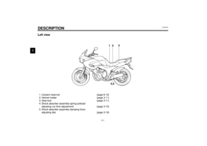 12
12 13
13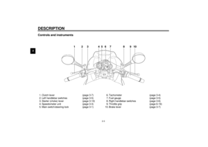 14
14 15
15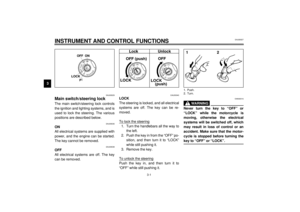 16
16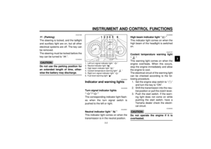 17
17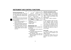 18
18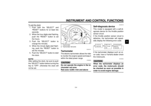 19
19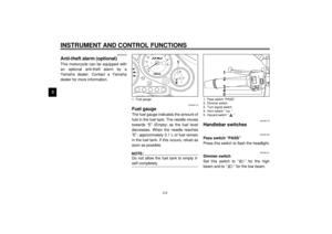 20
20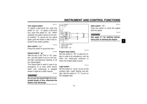 21
21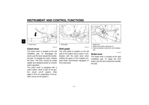 22
22 23
23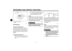 24
24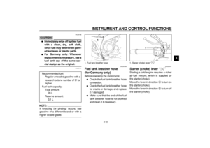 25
25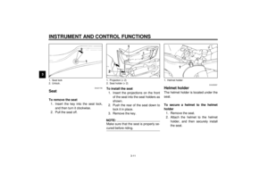 26
26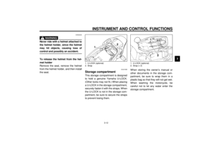 27
27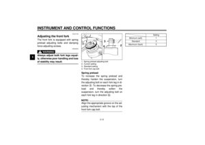 28
28 29
29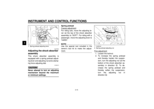 30
30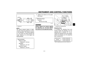 31
31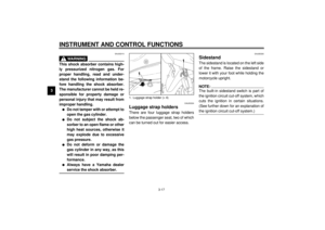 32
32 33
33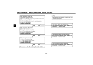 34
34 35
35 36
36 37
37 38
38 39
39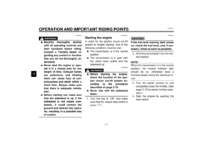 40
40 41
41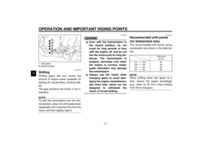 42
42 43
43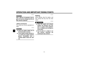 44
44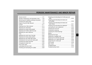 45
45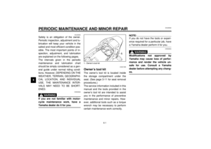 46
46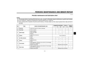 47
47 48
48 49
49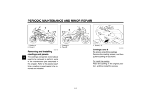 50
50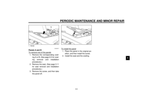 51
51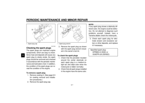 52
52 53
53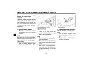 54
54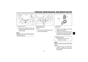 55
55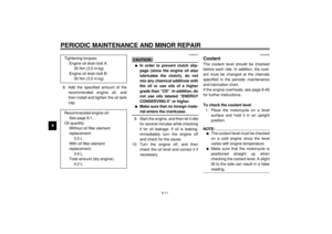 56
56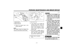 57
57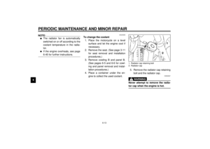 58
58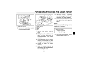 59
59 60
60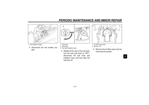 61
61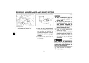 62
62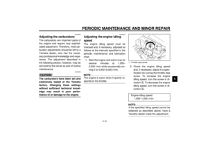 63
63 64
64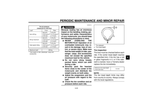 65
65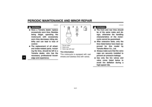 66
66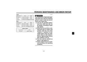 67
67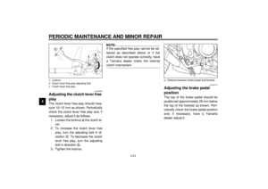 68
68 69
69 70
70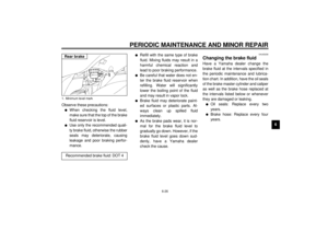 71
71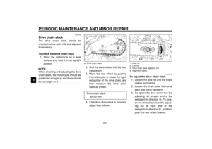 72
72 73
73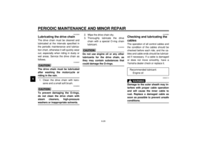 74
74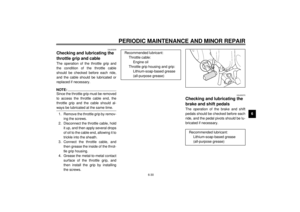 75
75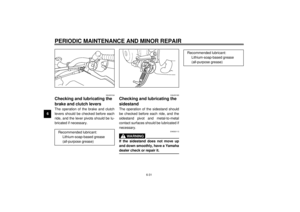 76
76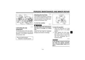 77
77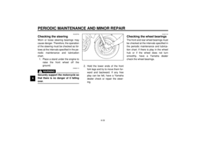 78
78 79
79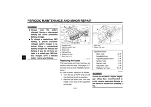 80
80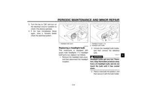 81
81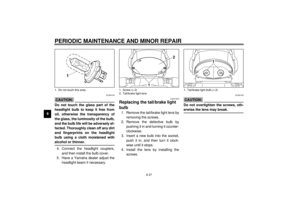 82
82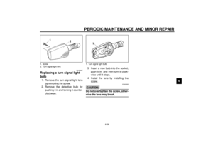 83
83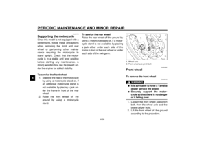 84
84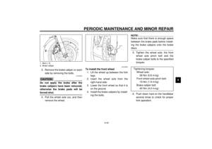 85
85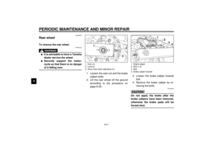 86
86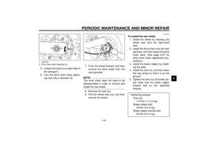 87
87 88
88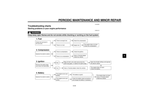 89
89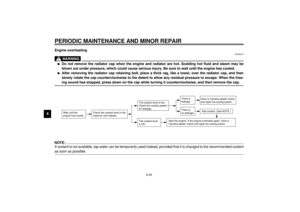 90
90 91
91 92
92 93
93 94
94 95
95 96
96 97
97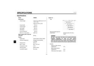 98
98 99
99 100
100 101
101 102
102 103
103 104
104 105
105 106
106 107
107 108
108 109
109
