Page 81 of 110
PERIODIC MAINTENANCE AND MINOR REPAIR
6-36
6 3. Turn the key to “ON” and turn on
the electrical circuit in question to
check if the device operates.
4. If the fuse immediately blows
again, have a Yamaha dealer
check the electrical system.
EAU03794
Replacing a headlight bulb This motorcycle is equipped with
quartz bulb headlights. If a headlight
bulb burns out, replace it as follows.
1. Remove the headlight bulb cover,
and then disconnect the headlight
couplers.2. Unhook the headlight bulb holder,
and then remove the defective
bulb.
EW000119
WARNING
_ Headlight bulbs get very hot. There-
fore, keep flammable products away
from a lit headlight bulb, and do not
touch the bulb until it has cooled
down. _3. Place a new bulb into position, and
then secure it with the bulb holder.
1. Headlight bulb cover
1. Headlight coupler (´ 2)
2. Headlight bulb holder
E_4tx.book Page 36 Wednesday, October 4, 2000 4:28 PM
Page 82 of 110

PERIODIC MAINTENANCE AND MINOR REPAIR
6-37
6
EC000105
CAUTION:_ Do not touch the glass part of the
headlight bulb to keep it free from
oil, otherwise the transparency of
the glass, the luminosity of the bulb,
and the bulb life will be adversely af-
fected. Thoroughly clean off any dirt
and fingerprints on the headlight
bulb using a cloth moistened with
alcohol or thinner. _4. Connect the headlight couplers,
and then install the bulb cover.
5. Have a Yamaha dealer adjust the
headlight beam if necessary.
EAU01623
Replacing the tail/brake light
bulb 1. Remove the tail/brake light lens by
removing the screws.
2. Remove the defective bulb by
pushing it in and turning it counter-
clockwise.
3. Insert a new bulb into the socket,
push it in, and then turn it clock-
wise until it stops.
4. Install the lens by installing the
screws.
EC000108
CAUTION:@ Do not overtighten the screws, oth-
erwise the lens may break. @
1. Do not touch this area.
1. Screw (´ 2)
2. Tail/brake light lens
1. Tail/brake light bulb (´ 2)
E_4tx.book Page 37 Wednesday, October 4, 2000 4:28 PM
Page 83 of 110
PERIODIC MAINTENANCE AND MINOR REPAIR
6-38
6
EAU03497
Replacing a turn signal light
bulb 1. Remove the turn signal light lens
by removing the screw.
2. Remove the defective bulb by
pushing it in and turning it counter-
clockwise.3. Insert a new bulb into the socket,
push it in, and then turn it clock-
wise until it stops.
4. Install the lens by installing the
screw.
ECA00065
CAUTION:@ Do not overtighten the screw, other-
wise the lens may break. @
1. Screw
2. Turn signal light lens
1. Turn signal light bulb
E_4tx.book Page 38 Wednesday, October 4, 2000 4:28 PM
Page 84 of 110

PERIODIC MAINTENANCE AND MINOR REPAIR
6-39
6
EAU01579
Supporting the motorcycle Since this model is not equipped with a
centerstand, follow these precautions
when removing the front and rear
wheel or performing other mainte-
nance requiring the motorcycle to
stand upright. Check that the motor-
cycle is in a stable and level position
before starting any maintenance. A
strong wooden box can be placed un-
der the engine for added stability.
To service the front wheel
1. Stabilize the rear of the motorcycle
by using a motorcycle stand or, if
an additional motorcycle stand is
not available, by placing a jack un-
der the frame in front of the rear
wheel.
2. Raise the front wheel off the
ground by using a motorcycle
stand.To service the rear wheel
Raise the rear wheel off the ground by
using a motorcycle stand or, if a motor-
cycle stand is not available, by placing
a jack either under each side of the
frame in front of the rear wheel or under
each side of the swingarm.
EAU03498*
Front wheel To remove the front wheel
EW000122
WARNING
@ l
It is advisable to have a Yamaha
dealer service the wheel.
l
Securely support the motor-
cycle so that there is no danger
of it falling over.
@1. Loosen the front wheel axle pinch
bolt, then the wheel axle and the
brake caliper bolts.
2. Lift the front wheel off the ground
according to the procedure.1. Wheel axle
2. Front wheel axle pinch bolt
E_4tx.book Page 39 Wednesday, October 4, 2000 4:28 PM
Page 85 of 110

PERIODIC MAINTENANCE AND MINOR REPAIR
6-40
6 3. Remove the brake caliper on each
side by removing the bolts.
ECA00046
CAUTION:@ Do not apply the brake after the
brake calipers have been removed,
otherwise the brake pads will be
forced shut. @4. Pull the wheel axle out, and then
remove the wheel.
EAU03829
To install the front wheel
1. Lift the wheel up between the fork
legs.
2. Insert the wheel axle from the
right-hand side.
3. Lower the front wheel so that it is
on the ground.
4. Install the brake calipers by install-
ing the bolts.
NOTE:_ Make sure that there is enough space
between the brake pads before install-
ing the brake calipers onto the brake
discs. _5. Tighten the wheel axle, the front
wheel axle pinch bolt and the
brake caliper bolts to the specified
torques.
6. Push down hard on the handlebar
several times to check for proper
fork operation.
1. Bolt (´ 2)
2. Brake caliper
Tightening torques:
Wheel axle:
58 Nm (5.8 m·kg)
Front wheel axle pinch bolt:
19 Nm (1.9 m·kg)
Brake caliper bolt:
40 Nm (4.0 m·kg)
E_4tx.book Page 40 Wednesday, October 4, 2000 4:28 PM
Page 86 of 110
PERIODIC MAINTENANCE AND MINOR REPAIR
6-41
6
EAU03830
Rear wheel To remove the rear wheel
EW000122
WARNING
_ l
It is advisable to have a Yamaha
dealer service the wheel.
l
Securely support the motor-
cycle so that there is no danger
of it falling over.
_
1. Loosen the axle nut and the brake
caliper bolts.
2. Lift the rear wheel off the ground
according to the procedure on
page 6-39.3. Loosen the brake caliper bracket
bolt.
4. Remove the brake caliper by re-
moving the bolts.
ECA00046
CAUTION:_ Do not apply the brake after the
brake calipers have been removed,
otherwise the brake pads will be
forced shut. _
1. Axle nut
2. Locknut
3. Drive chain slack adjusting nut
1. Brake caliper
2. Bolt (´ 2)
3. Bolt
4. Brake caliper bracket
E_4tx.book Page 41 Wednesday, October 4, 2000 4:28 PM
Page 87 of 110

PERIODIC MAINTENANCE AND MINOR REPAIR
6-42
6 5. Loosen the locknut on each side of
the swingarm.
6. Turn the drive chain slack adjust-
ing nuts fully in direction
a.7. Push the wheel forward, and then
remove the drive chain from the
rear sprocket.
NOTE:_ The drive chain does not need to be
disassembled in order to remove and
install the rear wheel. _8. Remove the axle nut.
9. Pull the wheel axle out, and then
remove the wheel.
EAU03501
To install the rear wheel
1. Install the wheel by inserting the
wheel axle from the right-hand
side.
2. Install the drive chain onto the rear
sprocket, and then adjust the drive
chain slack. (See page 6-27 for
drive chain slack adjustment pro-
cedures.)
3. Install the brake caliper by install-
ing the bolts.
4. Install the axle nut, and then lower
the rear wheel so that it is on the
ground.
5. Tighten the axle nut, the brake cal-
iper bolts and the brake caliper
bracket bolt to the specified
torques.
1. Locknut
2. Drive chain slack adjusting nut
Tightening torques:
Axle nut:
110 Nm (11.0 m·kg)
Brake caliper bolt:
40 Nm (4.0 m·kg)
Brake caliper bracket bolt:
35 Nm (3.5 m·kg)
E_4tx.book Page 42 Wednesday, October 4, 2000 4:28 PM
Page 88 of 110
PERIODIC MAINTENANCE AND MINOR REPAIR
6-43
6
EAU03087
Troubleshooting Although Yamaha motorcycles receive
a thorough inspection before shipment
from the factory, trouble may occur dur-
ing operation. Any problem in the fuel,
compression, or ignition systems, for
example, can cause poor starting and
loss of power.
The following troubleshooting charts
represent quick and easy procedures
for checking these vital systems your-
self. However, should your motorcycle
require any repair, take it to a Yamaha
dealer, whose skilled technicians have
the necessary tools, experience, and
know-how to service the motorcycle
properly.
Use only genuine Yamaha replace-
ment parts. Imitation parts may look
like Yamaha parts, but they are often
inferior, have a shorter service life and
can lead to expensive repair bills. E_4tx.book Page 43 Wednesday, October 4, 2000 4:28 PM
 1
1 2
2 3
3 4
4 5
5 6
6 7
7 8
8 9
9 10
10 11
11 12
12 13
13 14
14 15
15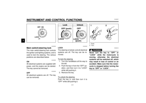 16
16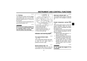 17
17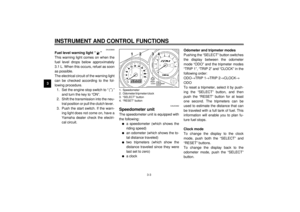 18
18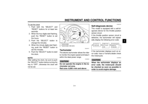 19
19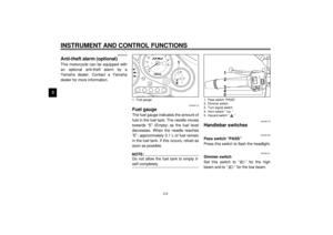 20
20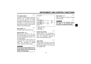 21
21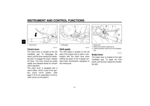 22
22 23
23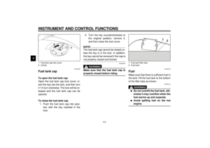 24
24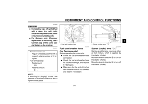 25
25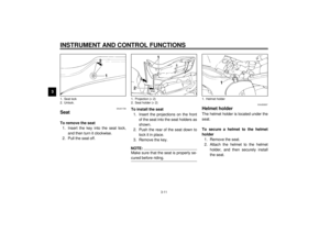 26
26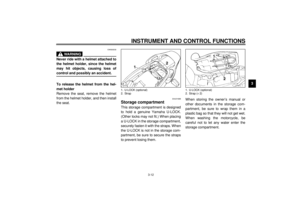 27
27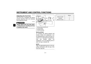 28
28 29
29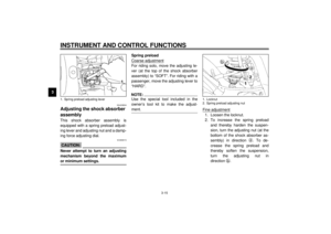 30
30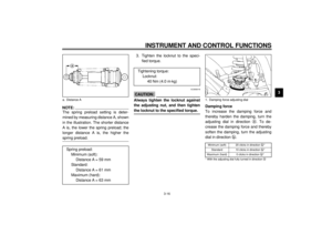 31
31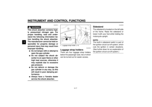 32
32 33
33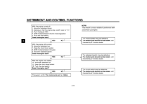 34
34 35
35 36
36 37
37 38
38 39
39 40
40 41
41 42
42 43
43 44
44 45
45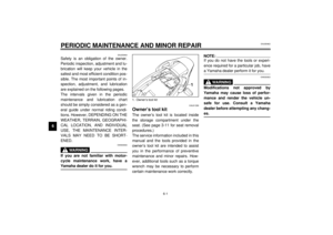 46
46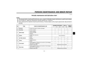 47
47 48
48 49
49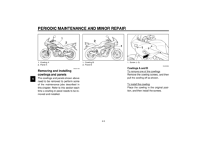 50
50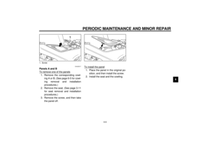 51
51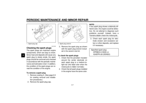 52
52 53
53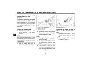 54
54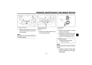 55
55 56
56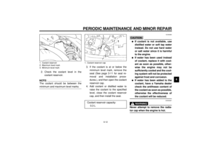 57
57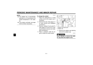 58
58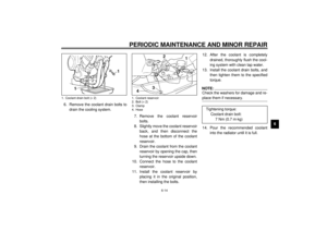 59
59 60
60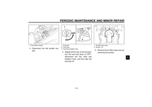 61
61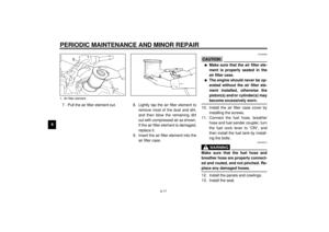 62
62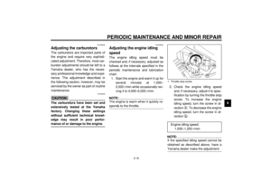 63
63 64
64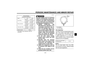 65
65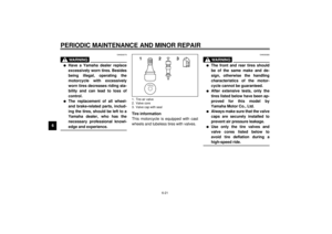 66
66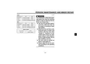 67
67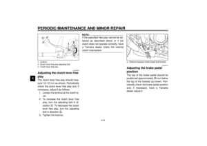 68
68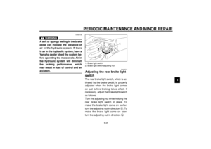 69
69 70
70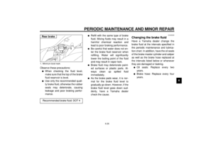 71
71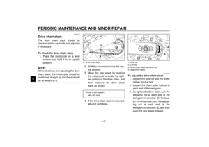 72
72 73
73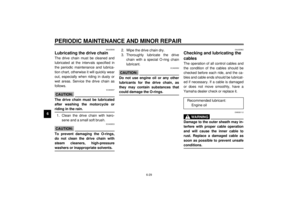 74
74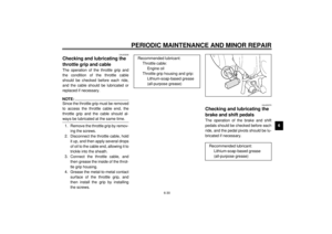 75
75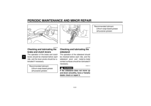 76
76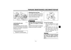 77
77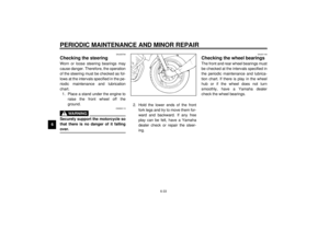 78
78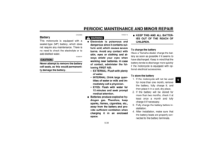 79
79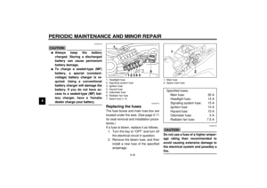 80
80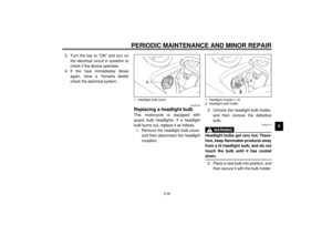 81
81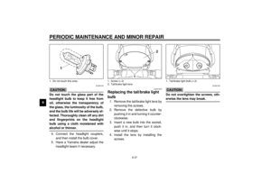 82
82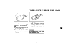 83
83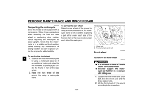 84
84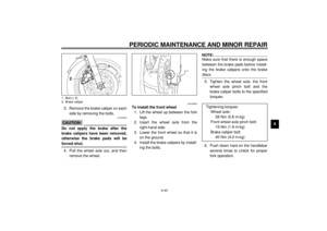 85
85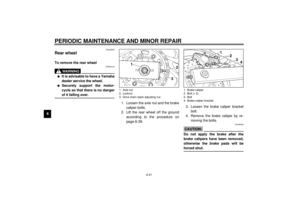 86
86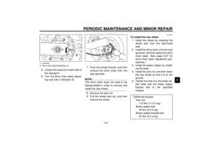 87
87 88
88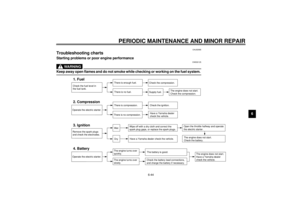 89
89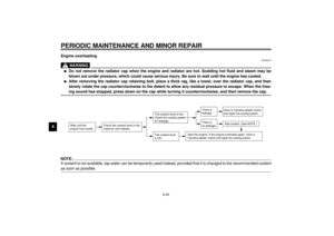 90
90 91
91 92
92 93
93 94
94 95
95 96
96 97
97 98
98 99
99 100
100 101
101 102
102 103
103 104
104 105
105 106
106 107
107 108
108 109
109


