Page 25 of 110

INSTRUMENT AND CONTROL FUNCTIONS
3-10
3
EAU00186
CAUTION:_ l
Immediately wipe off spilled fuel
with a clean, dry, soft cloth,
since fuel may deteriorate paint-
ed surfaces or plastic parts.
l
For Germany only: Whenever
replacement is necessary, use a
fuel tank cap of the same spe-
cial design as the original.
_
EAU00191
NOTE:_ If knocking (or pinging) occurs, use
gasoline of a different brand or with a
higher octane grade. _
EAU00196
Fuel tank breather hose
(for Germany only) Before operating the motorcycle:l
Check the fuel tank breather hose
connection.
l
Check the fuel tank breather hose
for cracks or damage, and replace
it if damaged.
l
Make sure that the end of the fuel
tank breather hose is not blocked
and clean it if necessary.
EAU02976*
Starter (choke) lever “ ”Starting a cold engine requires a richer
air-fuel mixture, which is supplied by
the starter (choke).
Move the lever in direction
a to turn on
the starter (choke).
Move the lever in direction
b to turn off
the starter (choke). Recommended fuel:
Regular unleaded gasoline with a
research octane number of 91 or
higher
Fuel tank capacity:
Total amount:
20 L
Reserve amount:
3.1 L
1. Fuel tank breather hose
1. Starter (choke) lever “ ”
E_4tx.book Page 10 Wednesday, October 4, 2000 4:28 PM
Page 26 of 110
INSTRUMENT AND CONTROL FUNCTIONS
3-11
3
EAU01726
Seat To remove the seat
1. Insert the key into the seat lock,
and then turn it clockwise.
2. Pull the seat off.To install the seat
1. Insert the projections on the front
of the seat into the seat holders as
shown.
2. Push the rear of the seat down to
lock it in place.
3. Remove the key.
NOTE:@ Make sure that the seat is properly se-
cured before riding. @
EAU00263*
Helmet holder The helmet holder is located under the
seat.
To secure a helmet to the helmet
holder
1. Remove the seat.
2. Attach the helmet to the helmet
holder, and then securely install
the seat.
1. Seat lock
2. Unlock.
1. Projection (´ 2)
2. Seat holder (´ 2)
1. Helmet holder
E_4tx.book Page 11 Wednesday, October 4, 2000 4:28 PM
Page 27 of 110

INSTRUMENT AND CONTROL FUNCTIONS
3-12
3
EW000030
WARNING
@ Never ride with a helmet attached to
the helmet holder, since the helmet
may hit objects, causing loss of
control and possibly an accident. @To release the helmet from the hel-
met holder
Remove the seat, remove the helmet
from the helmet holder, and then install
the seat.
EAU01688
Storage compartment This storage compartment is designed
to hold a genuine Yamaha U-LOCK.
(Other locks may not fit.) When placing
a U-LOCK in the storage compartment,
securely fasten it with the straps. When
the U-LOCK is not in the storage com-
partment, be sure to secure the straps
to prevent losing them.When storing the owner’s manual or
other documents in the storage com-
partment, be sure to wrap them in a
plastic bag so that they will not get wet.
When washing the motorcycle, be
careful not to let any water enter the
storage compartment. 1. U-LOCK (optional)
2. Strap
1. U-LOCK (optional)
2. Strap (´ 2)
E_4tx.book Page 12 Wednesday, October 4, 2000 4:28 PM
Page 28 of 110
INSTRUMENT AND CONTROL FUNCTIONS
3-13
3
EAU01728
Adjusting the front fork The front fork is equipped with spring
preload adjusting bolts and damping
force adjusting screws.
EW000035
WARNING
@ Always adjust both fork legs equal-
ly, otherwise poor handling and loss
of stability may result. @
Spring preload
To increase the spring preload and
thereby harden the suspension, turn
the adjusting bolt on each fork leg in di-
rection
a. To decrease the spring pre-
load and thereby soften the
suspension, turn the adjusting bolt on
each fork leg in direction
b.NOTE:@ Align the appropriate groove on the ad-
justing mechanism with the top of the
front fork cap bolt. @
CI-10E
1. Spring preload adjusting bolt
2. Current setting
3. Standard setting
4. Front fork cap bolt
Setting
Minimum (soft) 1
Standard 3
Maximum (hard) 5
E_4tx.book Page 13 Wednesday, October 4, 2000 4:28 PM
Page 29 of 110

INSTRUMENT AND CONTROL FUNCTIONS
3-14
3
Damping force
To increase the damping force and
thereby harden the damping, turn the
adjusting screw on each fork leg in di-
rection
a. To decrease the damping
force and thereby soften the damping,
turn the adjusting screw on each fork
leg in direction
b.
CI-02EEC000015
CAUTION:@ Never attempt to turn an adjusting
mechanism beyond the maximum
or minimum settings. @NOTE:@ Although the total number of clicks of a
damping force adjusting mechanism
may not exactly match the above spec-
ifications due to small differences in
production, the actual number of clicks
always represents the entire adjusting
range. To obtain a precise adjustment,
it would be advisable to check the num-
ber of clicks of each damping force ad-
justing mechanism and to modify the
specifications as necessary. @
1. Damping force adjusting screwMinimum (soft) 0 clicks in direction
a*
Standard 1 click in direction
a*
Maximum (hard) 4 clicks in direction
a*
* With the adjusting screw fully turned in direction
b
E_4tx.book Page 14 Wednesday, October 4, 2000 4:28 PM
Page 30 of 110

INSTRUMENT AND CONTROL FUNCTIONS
3-15
3
EAU03834
Adjusting the shock absorber
assembly This shock absorber assembly is
equipped with a spring preload adjust-
ing lever and adjusting nut and a damp-
ing force adjusting dial.
EC000015
CAUTION:_ Never attempt to turn an adjusting
mechanism beyond the maximum
or minimum settings. _
Spring preload
Coarse adjustmentFor riding solo, move the adjusting le-
ver (at the top of the shock absorber
assembly) to “SOFT”. For riding with a
passenger, move the adjusting lever to
“HARD”. NOTE:_ Use the special tool included in the
owner’s tool kit to make the adjust-
ment. _
Fine adjustment1. Loosen the locknut.
2. To increase the spring preload
and thereby harden the suspen-
sion, turn the adjusting nut (at the
bottom of the shock absorber as-
sembly) in direction
a. To de-
crease the spring preload and
thereby soften the suspension,
turn the adjusting nut in
direction
b.
1. Spring preload adjusting lever
1. Locknut
2. Spring preload adjusting nut
E_4tx.book Page 15 Wednesday, October 4, 2000 4:28 PM
Page 31 of 110

INSTRUMENT AND CONTROL FUNCTIONS
3-16
3
NOTE:_ The spring preload setting is deter-
mined by measuring distance A, shown
in the illustration. The shorter distance
A is, the lower the spring preload; the
longer distance A is, the higher the
spring preload. _
3. Tighten the locknut to the speci-
fied torque.
EC000018
CAUTION:_ Always tighten the locknut against
the adjusting nut, and then tighten
the locknut to the specified torque. _
Damping force
To increase the damping force and
thereby harden the damping, turn the
adjusting dial in direction
a. To de-
crease the damping force and thereby
soften the damping, turn the adjusting
dial in direction
b.CI-04E
a. Distance A
Spring preload:
Minimum (soft):
Distance A = 59 mm
Standard:
Distance A = 61 mm
Maximum (hard):
Distance A = 63 mm
Tightening torque:
Locknut:
40 Nm (4.0 m·kg)
1. Damping force adjusting dialMinimum (soft) 20 clicks in direction
b*
Standard 10 clicks in direction
b*
Maximum (hard) 0 clicks in direction
b*
* With the adjusting dial fully turned in direction
a
E_4tx.book Page 16 Wednesday, October 4, 2000 4:28 PM
Page 32 of 110

INSTRUMENT AND CONTROL FUNCTIONS
3-17
3
EAU00315
WARNING
@ This shock absorber contains high-
ly pressurized nitrogen gas. For
proper handling, read and under-
stand the following information be-
fore handling the shock absorber.
The manufacturer cannot be held re-
sponsible for property damage or
personal injury that may result from
improper handling.l
Do not tamper with or attempt to
open the gas cylinder.
l
Do not subject the shock ab-
sorber to an open flame or other
high heat sources, otherwise it
may explode due to excessive
gas pressure.
l
Do not deform or damage the
gas cylinder in any way, as this
will result in poor damping per-
formance.
l
Always have a Yamaha dealer
service the shock absorber.
@
EAU00324
Luggage strap holders There are four luggage strap holders
below the passenger seat, two of which
can be turned out for easier access.
EAU00330
Sidestand The sidestand is located on the left side
of the frame. Raise the sidestand or
lower it with your foot while holding the
motorcycle upright.NOTE:@ The built-in sidestand switch is part of
the ignition circuit cut-off system, which
cuts the ignition in certain situations.
(See further down for an explanation of
the ignition circuit cut-off system.) @
1. Luggage strap holder (´ 4)
E_4tx.book Page 17 Wednesday, October 4, 2000 4:28 PM
 1
1 2
2 3
3 4
4 5
5 6
6 7
7 8
8 9
9 10
10 11
11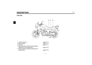 12
12 13
13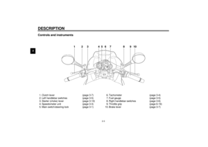 14
14 15
15 16
16 17
17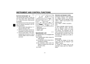 18
18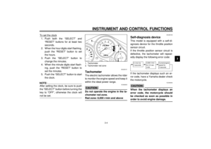 19
19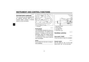 20
20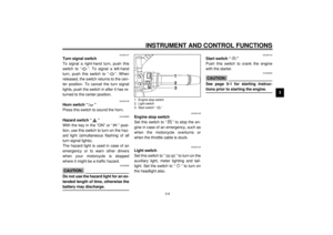 21
21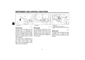 22
22 23
23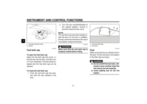 24
24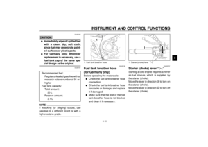 25
25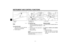 26
26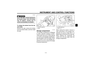 27
27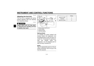 28
28 29
29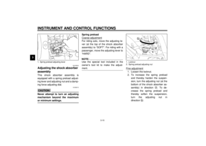 30
30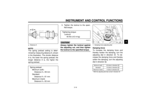 31
31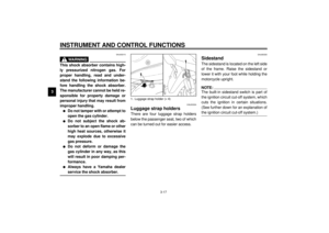 32
32 33
33 34
34 35
35 36
36 37
37 38
38 39
39 40
40 41
41 42
42 43
43 44
44 45
45 46
46 47
47 48
48 49
49 50
50 51
51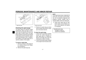 52
52 53
53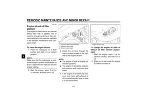 54
54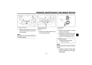 55
55 56
56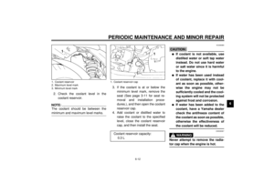 57
57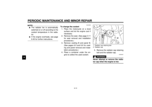 58
58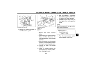 59
59 60
60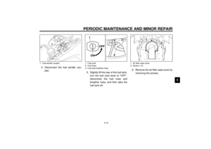 61
61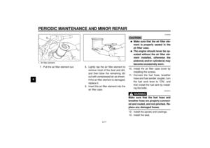 62
62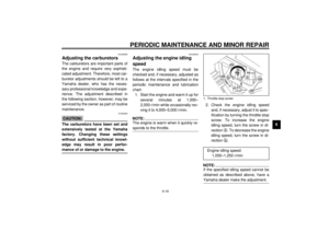 63
63 64
64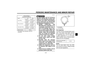 65
65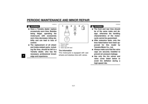 66
66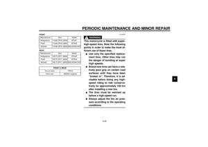 67
67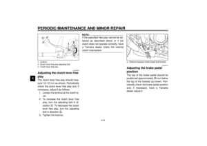 68
68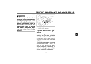 69
69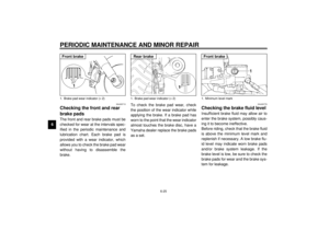 70
70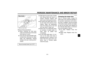 71
71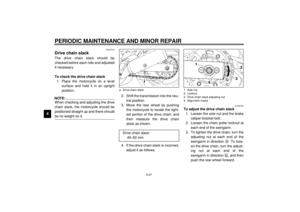 72
72 73
73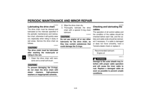 74
74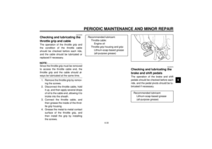 75
75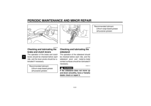 76
76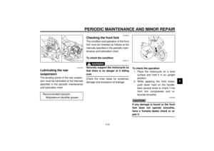 77
77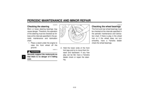 78
78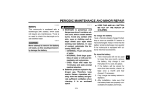 79
79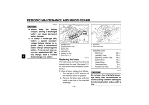 80
80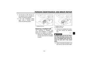 81
81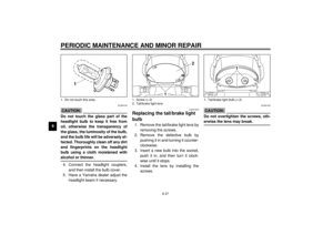 82
82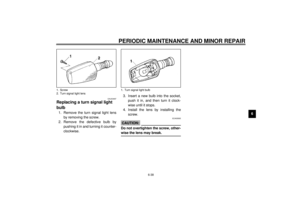 83
83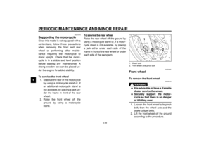 84
84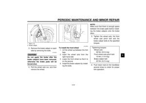 85
85 86
86 87
87 88
88 89
89 90
90 91
91 92
92 93
93 94
94 95
95 96
96 97
97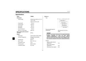 98
98 99
99 100
100 101
101 102
102 103
103 104
104 105
105 106
106 107
107 108
108 109
109
