Page 2084 of 4323
I18725
Back Door ECU
BKUL
12G B12
Back Door Key Lock and Unlock SW
3R±W
LKEYE
BKL 5 4 B1019
B10
B10 DI±1882
± DIAGNOSTICSBACK DOOR CONTROL SYSTEM
2076 Author�: Date�:
2005 SEQUOIA (RM1146U)
Back door key lock and unlock switch circuit
CIRCUIT DESCRIPTION
The back door ECU operates the back door lock motor based on information from the back door key lock
and unlock switch.
The back door power window goes up when the key is inserted into the cylinder and turned to the LOCK
position. The window goes down when the key is turned to the UNLOCK position.
WIRING DIAGRAM
DI94L±05
Page 2085 of 4323

INSPECTION PROCEDURE
HINT:
When using the hand±held tester, start the inspection from step 1 and when not")
± DIAGNOSTICSBACK DOOR CONTROL SYSTEM
DI±1883
2077 Author�: Date�:
2005 SEQUOIA (RM1146U)
INSPECTION PROCEDURE
HINT:
When using the hand±held tester, start the inspection from step 1 and when not using the hand±held tester,
start from step 2.
1 Check the back door key lock and unlock switch using hand±held tester.
PREPARATION:
(a) Connect the hand±held tester to the DLC3.
(b) Turn the ignition switch ON.
CHECK:
According to the display on the tester, read the DATA LIST.
BACK±DOOR:
ItemMeasurement Item/
Display (Range)Normal ConditionDiagnostic Note
KEY SW (UNLOCK)Unlock SW linked with
the key/ON or OFFON: Back door lock is in unlock position
OFF: Back door lock is in lock position±
KEY SW (LOCK)Unlock SW linked with
the key/ON or OFFON: Back door lock is in lock position
OFF: Back door lock is in unlock position±
UP/DOOR KEY
Back door key lock
and unlock switch
linked window open
and close/AVAIL or
NOT AVL
AVAIL: Key±linked open and close SET
NOT AVL: Key±linked open and close UNSET*1
DOWN/DOOR KEY
Back door key lock
and unlock switch
linked window open
and close/AVAIL or
NOT AVL
AVAIL: Key±linked open and close SET
NOT AVL: Key±linked open and close UNSET*1
*1: When the ignition key is not in the key cylinder and the back door is locked, turning and holding the back
door key in the lock position for 1.5 seconds or more activates the back door ECU to operate the power win-
dow motor and close the power window.
Similarly, turning and holding the back door key in the unlock position for 1.5 seconds or more when the back
door is unlocked will open the power window.
OK:
Indication on the tester switches between ON and OFF in accordance with the back door key
lock and unlock switch status.
OK Proceed to next circuit inspection shown in
problem symptoms table (See page DI±1854).
NG
Page 2086 of 4323
DI±1884
± DIAGNOSTICSBACK DOOR CONTROL SYSTEM
2078 Author�: Date�:
2005 SEQUOIA (RM1146U)
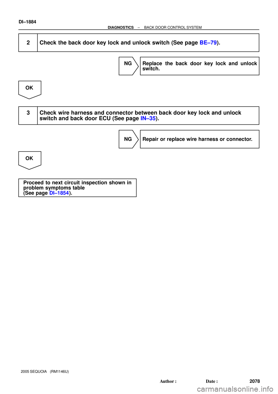
2 Check the back door key lock and unlock switch (See page BE±79).
NG Replace the back door key lock and unlock
switch.
OK
3 Check wire harness and connector between back door key lock and unlock
switch and back door ECU (See page IN±35).
NG Repair or replace wire harness or connector.
OK
Proceed to next circuit inspection shown in
problem symptoms table
(See page DI±1854).
Page 2087 of 4323
I28435
Back Door ECU
P 1
2L±R R16
Rear Wiper Motor
L±B3
3
L±WW
SGND 12
18
B10 B10 B10
P
E W
± DIAGNOSTICSBACK DOOR CONTROL SYSTEM
DI±1885
2079 Author�: Date�:
2005 SEQUOIA (RM1146U)
Rear wiper limit switch circuit
CIRCUIT DESCRIPTION
The rear wiper limit switch is built in to the rear wiper motor. The W built in switch of the rear wiper motor is
ON when the rear wiper arm is in the position between stop and reverse and OFF when the rear wiper arm
is in any other position. The P built in switch of the rear wiper motor is OFF when the rear wiper arm is in
any position except stored and ON when the rear wiper arm is in the stored position.
WIRING DIAGRAM
DI94J±04
Page 2088 of 4323
DI±1886
± DIAGNOSTICSBACK DOOR CONTROL SYSTEM
2080 Author�: Date�:
2005 SEQUOIA (RM1146U)
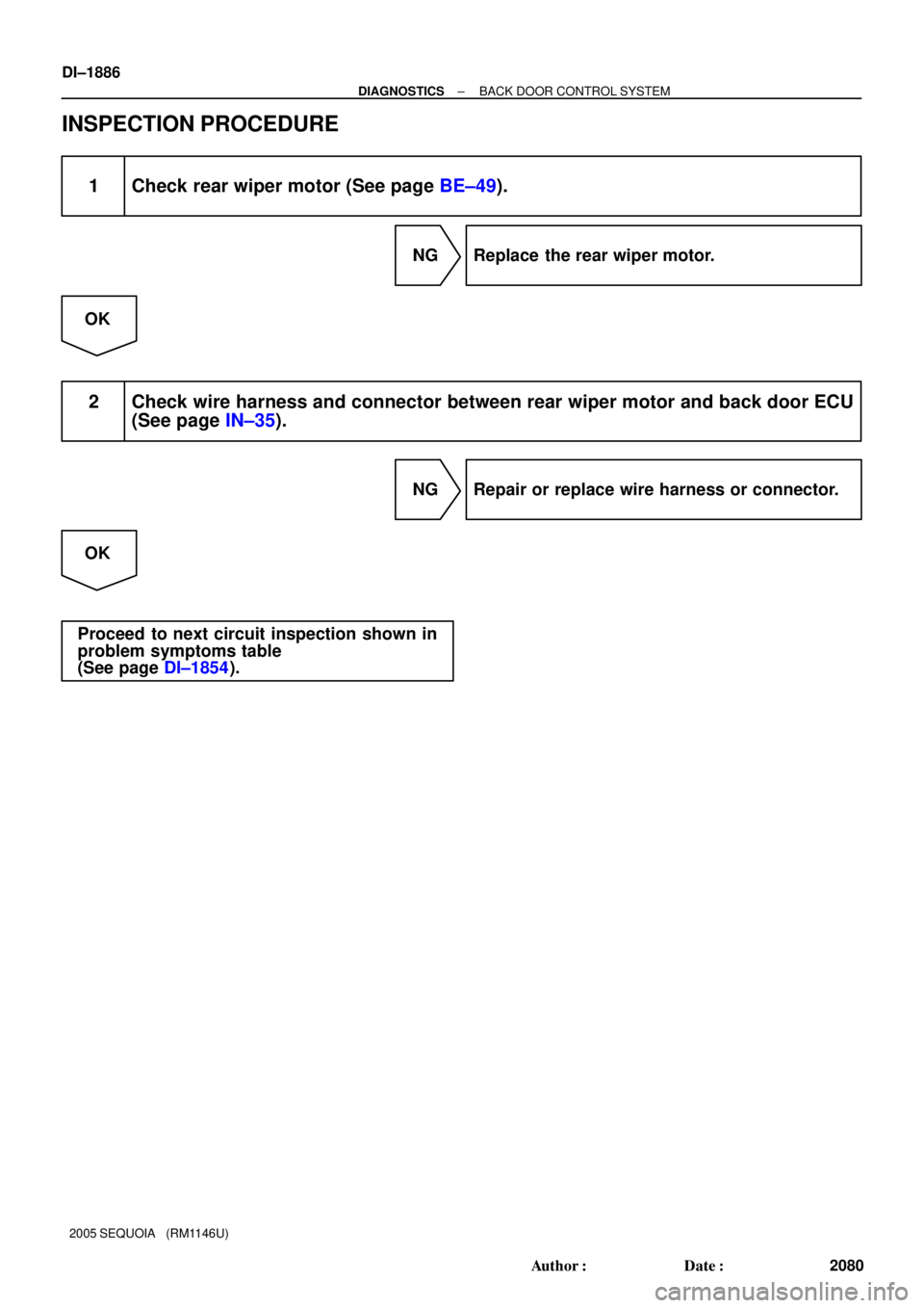
INSPECTION PROCEDURE
1 Check rear wiper motor (See page BE±49).
NG Replace the rear wiper motor.
OK
2 Check wire harness and connector between rear wiper motor and back door ECU
(See page IN±35).
NG Repair or replace wire harness or connector.
OK
Proceed to next circuit inspection shown in
problem symptoms table
(See page DI±1854).
Page 2090 of 4323
DIDF7±01
I28466
DLC 3Front
Passenger
Door ECUBody ECU
A/C ECU Combination
MeterBack Door
ECUDriver Door
ECU
MPX1
MPX2
MPX3
Slide Roof
ECU Memory
Seat ECU
& SwitchMPX1 MPX2 MPX1 MPX2 MPX1 MPX2
MPX± MPX+
MPX1 MPX1
SILAutomatic Light
Control Sensor
Wireless Door
Control Receiver
Airbag Sensor Assy
Diagnostic Bus
BEANCLTS
CLTB
CLTE
PRG
GSW
OBD2PDA DI±1888
± DIAGNOSTICSMULTIPLEX COMMUNICATION SYSTEM
2082 Author�: Date�:
2005 SEQUOIA (RM1146U)
SYSTEM DIAGRAM
Page 2091 of 4323
DIDFN±01
B78765I28978
Battery
Serial Communication Switch
ECUOn On
Off
ECULight
Motor
Heater
Solenoid � Conceptual Drawing �
I28977
Frame
Data
Header End Message
± DIAGNOSTICSMULTIPLEX COMMUNICATION SYSTEM
DI±1889
2083 Author�: Date�:
2005 SEQUOIA (RM1146U)
SYSTEM DESCRIPTION
Basic of MPX (Multiplex Communication)
1. General
The SEQUOIA multiplex communication system uses serial communication, which converts multiple pieces
of information into serial communication data. As a result, they can be transmitted through a single commu-
nication wire.
Serial communication data consists of bits and frames. A bit is the basic unit that represents the amount of
information. A bit is represented by a binary value º0º or º1º. A frame is a body of data that is transmitted
together. A frame contains a ºheaderº that indicates the beginning of the data and an ºend messageº that
indicates the end of the data.
Page 2092 of 4323
B78774I28976
ECU
ECUECU
ECU Daisy
Chain
Open DI±1890
± DIAGNOSTICSMULTIPLEX COMMUNICATION SYSTEM
2084 Author�: Date�:
2005 SEQUOIA (RM1146U)
2. Network Style
Based on serial communication, various ECUs are connected on a network to exchange various pieces of
information. Such a system is called a multiplex communication system.
�The BEAN (Body Electronics Area Network) uses the ring and bus styles of networks to connect ECUs.
This connection style is called a daisy chain. In the daisy chain, communication can be maintained
even if there is an area that has an open circuit.