Page 2001 of 4323

INSPECTION PROCEDURE
HINT:
When using the hand±held tester, start the inspection from step 1 and when n")
± DIAGNOSTICSDRIVER DOOR CONTROL SYSTEM
DI±1799
1993 Author�: Date�:
2005 SEQUOIA (RM1146U)
INSPECTION PROCEDURE
HINT:
When using the hand±held tester, start the inspection from step 1 and when not using the hand±held tester,
start from step 2.
1 Check power window motor using hand±held tester.
PREPARATION:
(a) Connect the hand±held tester to the DLC3.
(b) Turn the ignition switch ON.
CHECK:
According to the display on the tester, perform the ACTIVE TEST.
D±DOOR:
ItemTest DetailsDiagnostic Note
P/W UP/DOWNDrive the P/W Motor UP/DOWN
During this ACTIVE TEST, jam protection, caught
detection can be monitored.
(Refer to the DATA LIST for details)
OK:
Power window operates normally.
OK Proceed to next circuit inspection shown in
problem symptoms table (See page DI±1782).
NG
2 Check power window motor (See page BE±69).
NG Replace the power window motor.
OK
3 Check wire harness and connector between power window motor and driver
door ECU (See page IN±35).
NG Repair or replace wire harness or connector.
OK
Proceed to next circuit inspection shown in
problem symptoms table
(See page DI±1782).
Page 2002 of 4323
I28453
D22
Driver Door ECU P6
Power Window Motor
Front LH
Limit SwitchSGND
LMT 4
2 W±B
L±Y 5
4 DI±1800
± DIAGNOSTICSDRIVER DOOR CONTROL SYSTEM
1994 Author�: Date�:
2005 SEQUOIA (RM1146U)
Jam protection limit switch circuit
CIRCUIT DESCRIPTION
The jam protection limit switch, built in the power window motor, turns off before top dead center. The ECU
reads this ºOFFº signal and fully closes the window.
WIRING DIAGRAM
DI1PK±07
Page 2004 of 4323
DI±1802
± DIAGNOSTICSDRIVER DOOR CONTROL SYSTEM
1996 Author�: Date�:
2005 SEQUOIA (RM1146U)
3 Check wire harness and connector between jam protection limit switch and driv-
er door ECU (See page IN±35).
NG Repair or replace wire harness or connector.
OK
Proceed to next circuit inspection shown in
problem symptoms table (See page
DI±1782).
Page 2005 of 4323
I28454
D22
Driver Door ECU P6
Power Window Motor
Front LH
Pulse SensorSGND
PLS 4
3 W±B
L±R 5
3
± DIAGNOSTICSDRIVER DOOR CONTROL SYSTEM
DI±1803
1997 Author�: Date�:
2005 SEQUOIA (RM1146U)
Jam protection pulse sensor circuit
CIRCUIT DESCRIPTION
The jam protection pulse sensor, built in the power window motor, outputs a ON/OFF pulse when the motor
rotates.
WIRING DIAGRAM
DI1PL±09
Page 2006 of 4323
DI±1804
± DIAGNOSTICSDRIVER DOOR CONTROL SYSTEM
1998 Author�: Date�:
2005 SEQUOIA (RM1146U)
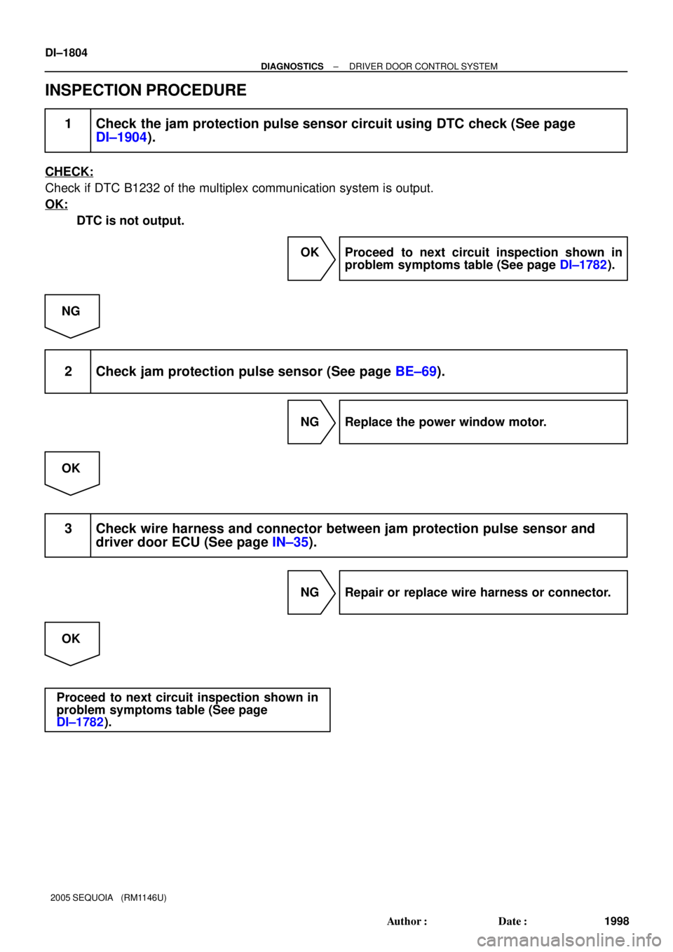
INSPECTION PROCEDURE
1 Check the jam protection pulse sensor circuit using DTC check (See page
DI±1904).
CHECK:
Check if DTC B1232 of the multiplex communication system is output.
OK:
DTC is not output.
OK Proceed to next circuit inspection shown in
problem symptoms table (See page DI±1782).
NG
2 Check jam protection pulse sensor (See page BE±69).
NG Replace the power window motor.
OK
3 Check wire harness and connector between jam protection pulse sensor and
driver door ECU (See page IN±35).
NG Repair or replace wire harness or connector.
OK
Proceed to next circuit inspection shown in
problem symptoms table (See page
DI±1782).
Page 2007 of 4323

I24364
D22
Driver Door ECU P4 Power Window
Control SW Rear RH
F18
Front Passenger Door ECU F10
Fusible Link Block
P3 Power Window Control
SW Rear LHE
B
L±O
5 W±B
PWR No. 4
R±L
WLSW U
D 3
5
24
BC1
A
J46L±O L±O 13
BC1 W±B
U
D5
2GR
2 1
BL±Y5
BA1L±YG
J30
L±Y
7
1G
8
1F
16
1F PWR No. 3 3
5
21 1
1L
9
1F
E
J6E
J7
E
J67
R±L
R±L
R±L
II1
LSW W±B
Battery
J8
J/CIE A W±B
BKW
85
B
BA1 13
W±B
BH ALTGR
2
1
3E
Power Main Relay
Instrument Panel J/B
J/C P9
Power
Window
Motor
Rear
RH P8
Power
Window
Motor
Rear
LH
7 4
5 N J/C
J/C
E J29
J47
± DIAGNOSTICSDRIVER DOOR CONTROL SYSTEM
DI±1805
1999 Author�: Date�:
2005 SEQUOIA (RM1146U)
Window lock switch circuit
CIRCUIT DESCRIPTION
The window lock switch circuit can be checked using the DTC check (refer to DI±1904).
The window lock switch is built in the driver door ECU. Voltage applied to the WLSW terminal of the driver
door ECU is shut off when the window lock switch is turned to the LOCK position. Thus the power main relay
stops power supply to the other power window control switches.
WIRING DIAGRAM
DI1PE±15
Page 2009 of 4323
± DIAGNOSTICSDRIVER DOOR CONTROL SYSTEM
DI±1807
2001 Author�: Date�:
2005 SEQUOIA (RM1146U)
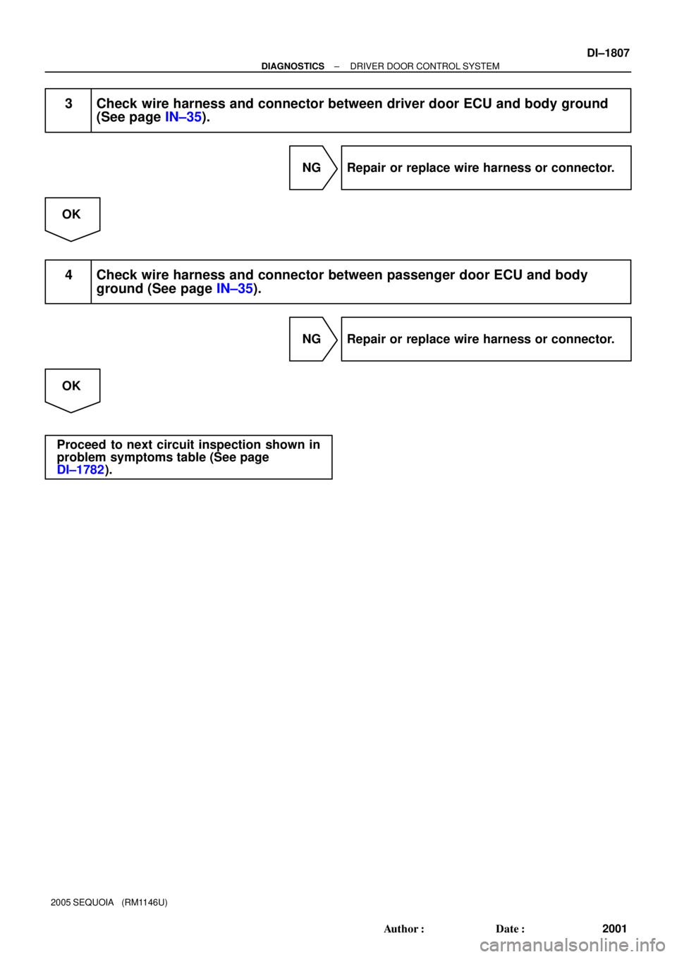
3 Check wire harness and connector between driver door ECU and body ground
(See page IN±35).
NG Repair or replace wire harness or connector.
OK
4 Check wire harness and connector between passenger door ECU and body
ground (See page IN±35).
NG Repair or replace wire harness or connector.
OK
Proceed to next circuit inspection shown in
problem symptoms table (See page
DI±1782).
Page 2010 of 4323
I28455
R17
Remote Control Mirror LHD22
Driver Door ECU
DM+R
DMVR
DMHR M+
MV
MHL±W
BR±B
BR±R 7
6
815
17
16 DI±1808
± DIAGNOSTICSDRIVER DOOR CONTROL SYSTEM
2002 Author�: Date�:
2005 SEQUOIA (RM1146U)
Remote control mirror motor LH circuit (w/ Driving position
memory)
CIRCUIT DESCRIPTION
SEQUOIA features a driving position memory function, and up to 2 driver positions can be memorized.
The driver door ECU operates 2 motors built into the remote control mirror. The motors move the mirror to
the memorized positions based on information from the position sensor.
WIRING DIAGRAM
DIDEP±01