Page 2569 of 4323
I28847
+B I19 Integration Control and Panel:
I22575
DOME Fuse Engine Room J/B
± DIAGNOSTICSAIR CONDITIONING SYSTEM
DI±2367
2561 Author�: Date�:
2005 SEQUOIA (RM1146U)
INSPECTION PROCEDURE
1 Check voltage between terminal +B of integration control and panel and body
ground.
PREPARATION:
Remove the integration control and panel with connectors still
connected.
CHECK:
Measure the voltage between terminal +B of the integration
control and panel and body ground.
OK:
Voltage : 10 to 14 V
OK Proceed to next circuit inspection shown in
problem symptoms table (See page DI±2304).
NG
2 Check DOME fuse.
PREPARATION:
Remove the DOME fuse from the engine room J/B.
CHECK:
Check continuity of the DOME fuse.
OK:
Continuity
NG Check for short in all the harness and compo-
nents connected to the DOME fuse (See at-
tached wiring diagram).
OK
Check and repair harness and connector between integration control and panel and battery.
Page 2571 of 4323
I28847
GNDI19 Integration Control and Panel:ACC
I22574
Instrument Panel J/B
CIG Fuse
± DIAGNOSTICSAIR CONDITIONING SYSTEM
DI±2369
2563 Author�: Date�:
2005 SEQUOIA (RM1146U)
INSPECTION PROCEDURE
1 Check voltage between terminals ACC and GND of integration control and panel.
PREPARATION:
Remove the integration control and panel with connectors still
connected.
CHECK:
(a) Turn the ignition switch to ACC.
(b) Measure the voltage between terminals ACC and GND of
the integration control and panel.
OK:
Voltage : 10 to 14 V
OK Proceed to next circuit inspection shown in
problem symptoms table (See page DI±2304).
NG
2 Check CIG fuse.
PREPARATION:
Remove the CIG fuse from the cowl side J/B.
CHECK:
Check continuity of the CIG fuse.
OK:
Continuity
NG Check for short in all the harness and compo-
nents connected to the CIG fuse (See attached
wiring diagram).
OK
Check and repair harness and connector between integration control and panel and battery.
Page 2577 of 4323
I07839
21
± DIAGNOSTICSAIR CONDITIONING SYSTEM
DI±2375
2569 Author�: Date�:
2005 SEQUOIA (RM1146U)
INSPECTION PROCEDURE
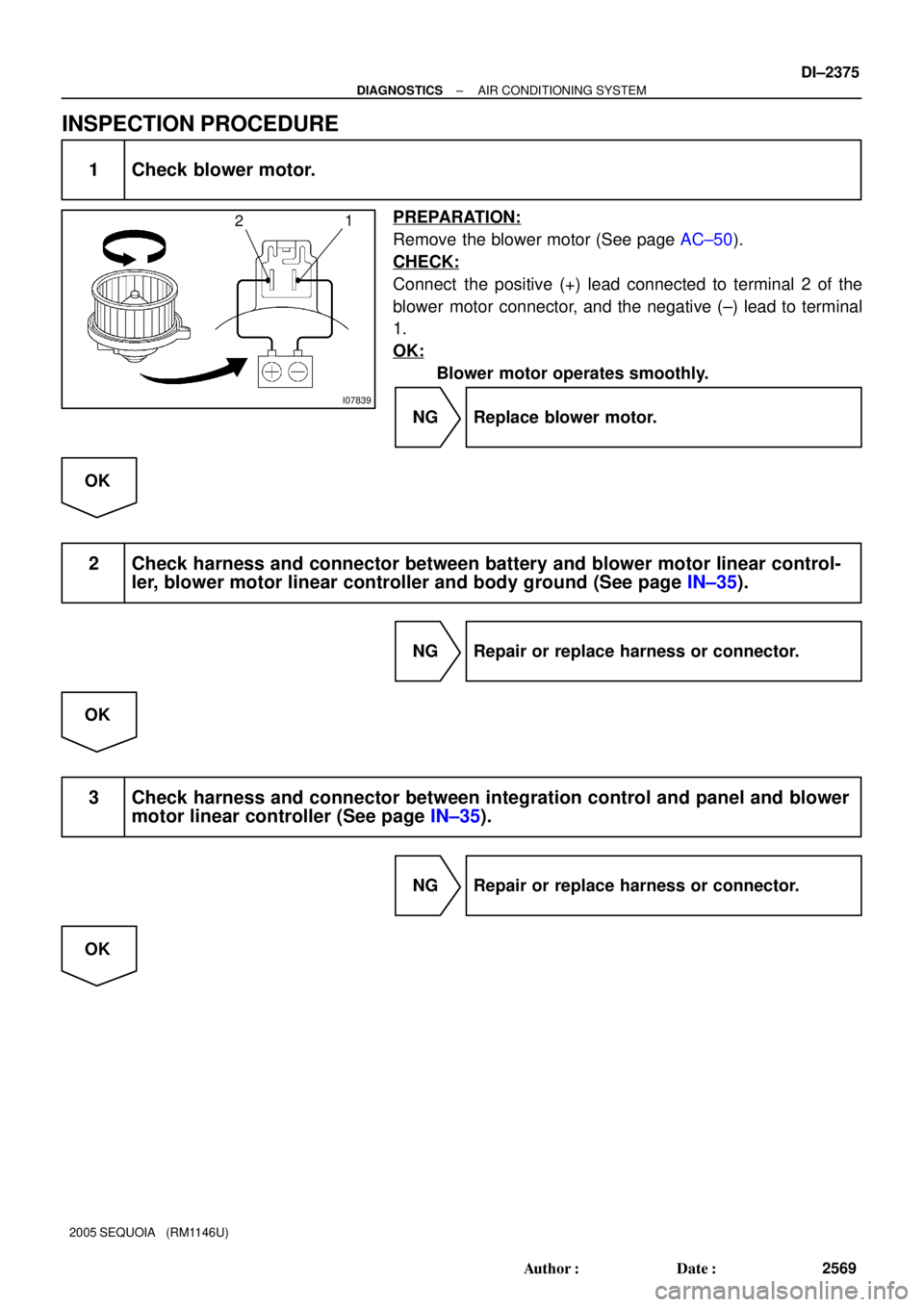
1 Check blower motor.
PREPARATION:
Remove the blower motor (See page AC±50).
CHECK:
Connect the positive (+) lead connected to terminal 2 of the
blower motor connector, and the negative (±) lead to terminal
1.
OK:
Blower motor operates smoothly.
NG Replace blower motor.
OK
2 Check harness and connector between battery and blower motor linear control-
ler, blower motor linear controller and body ground (See page IN±35).
NG Repair or replace harness or connector.
OK
3 Check harness and connector between integration control and panel and blower
motor linear controller (See page IN±35).
NG Repair or replace harness or connector.
OK
Page 2580 of 4323
I28847
RrBLWI21 Integration Control and Panel:
I24460
DI±2378
± DIAGNOSTICSAIR CONDITIONING SYSTEM
2572 Author�: Date�:
2005 SEQUOIA (RM1146U)
INSPECTION PROCEDURE
1 Check voltage between terminal RrBLW of integration control and panel and
body ground.
PREPARATION:
Remove the integration control and panel with connectors still
connected.
CHECK:
(a) Turn the ignition switch to ON.
(b) Operate the blower motor.
(c) Measure the voltage between terminal RrBLW of the in-
tegration control and panel and body ground.
OK:
Voltage: 1 to 3 V
OK Go to step 3.
NG
2 Check blower motor.
PREPARATION:
Remove the blower motor.
CHECK:
Connect the positive (+) lead from the battery to terminal 2 and
the negative (±) lead to terminal 1 of the blower motor connec-
tor.
OK:
Blower motor operates smoothly.
NG Replace blower motor.
OK
Page 2581 of 4323
I28847
RrVMI21 Integration Control and Panel:
± DIAGNOSTICSAIR CONDITIONING SYSTEM
DI±2379
2573 Author�: Date�:
2005 SEQUOIA (RM1146U)
3 Check voltage between terminal RrVM of integration control and panel and body
ground.
PREPARATION:
Remove the integration control and panel with connectors still
connected.
CHECK:
(a) Turn the ignition switch to ON.
(b) Operate the rear A/C blower motor.
(c) Measure the voltage between terminal RrVM of the in-
tegration control and panel and body ground, when the
blower switch is operated as shown in the table below.
OK:
Blower speedVoltage
LO7.2 V
ME4.2 V
HI0.5 V
OK Proceed to next circuit inspection shown in
problem symptoms table (See page DI±2304).
NG
Page 2582 of 4323
I07763
1
2
4
I07764
3
4
DI±2380
± DIAGNOSTICSAIR CONDITIONING SYSTEM
2574 Author�: Date�:
2005 SEQUOIA (RM1146U)
4 Check power transistor.
PREPARATION:
Remove the power transistor (See page AC±84).
CHECK:
(a) Connect the positive (+) lead from the battery to terminal
1 through a 12 V ± 3.4 W test bulb and the negative (±)
lead to terminal 2.
(b) Check the test bulb lights up when another positive (+)
lead is connected to terminal 4 through a 12 V ± 3.4 W test
bulb.
OK:
Test bulb lights up.
CHECK:
Measure the resistance between terminals 3 and 4.
OK:
Resistance: 2.0 to 2.4 kW
NG Replace power transistor.
OK
5 Check harness and connector between integration control and panel and power
transistor, power transistor and body ground (See page IN±35).
NG Repair or replace harness or connector.
OK
Replace integration control and panel.
Page 2583 of 4323
I28845
ECM
E5
E5G±BIntegration Control
and Panel
I22
ACT
AC1
8 25
24
L±W 2
21
5 MG CLT Relay
J3 J/C
15
IG4 C
C Engine Room J/B
2
2C4
2G
3
A3
A/C Magnetic Clutch
and Lock Sensor R±Y
IA1 LG±B5
4
Engine Room R/B No. 2
2 22 G±Y
MGC 5
I19 I22 ACT
AC1
IA5
R±Y1
L±W L±W
R±Y
L
L
± DIAGNOSTICSAIR CONDITIONING SYSTEM
DI±2381
2575 Author�: Date�:
2005 SEQUOIA (RM1146U)
Compressor Circuit
CIRCUIT DESCRIPTION
The integration control and panel outputs the magnetic clutch ON signal from terminal AC1 to the ECM.
When the ECM receives this signal, it sends a signal from terminal ACT and switches the A/C magnetic clutch
relay ON. This turns the A/C magnetic clutch on.
WIRING DIAGRAM
DIAA8±03
Page 2585 of 4323
± DIAGNOSTICSAIR CONDITIONING SYSTEM
DI±2383
2577 Author�: Date�:
2005 SEQUOIA (RM1146U)
3 Perform active test by hand±held tester.
PREPARATION:
(a) Connect the hand±held tester to the DLC3.
(b) Turn the ignition switch ON and push the hand±held tester main SW ON.
CHECK:
Select the item below in the DATA LIST, and read the displays on the hand±held tester.
AIR CONDITIONING:
ItemTest Details / Display (Range)Diagnostic Note
A/C MAG CLUTCHMagnet clutch relay / OFF, ONOperating sound can be heard
HINT:
Check with the engine running.
OK:
The operation sound of the MG CLT relay can be heard.
NG Go to step 5.
OK
4 Check harness and connector between integration control and panel (ACT termi-
nal) and ECM (ACT terminal) (See page IN±35).
NG Repair or replace harness or connector.
OK
Proceed to next circuit inspection shown in problem symptoms table (See page DI±2304).