Page 2586 of 4323
Z18060
15 2
3
12 3 5
I21361
3
DI±2384
± DIAGNOSTICSAIR CONDITIONING SYSTEM
2578 Author�: Date�:
2005 SEQUOIA (RM1146U)
5 Check magnetic clutch relay.
PREPARATION:
Remove the magnetic clutch relay from the engine room J/B.
CHECK:
Measure the resistance according to the value(s) in the table
below.
OK:
Tester connectionConditionSpecified condition
3 ± 5Always10 kW or higher
3 ± 5
Voltage is applied
between terminals
1 and 2Below 1W (Battery
voltage is applied between
terminals 1 and 2)
NG Replace magnetic clutch relay.
OK
6 Check A/C magnetic clutch.
PREPARATION:
Disconnect the magnetic clutch connector.
CHECK:
Connect the positive (+) battery lead to the magnetic clutch con-
nector terminal 3.
OK:
Magnetic clutch is energized.
NG Replace A/C magnetic clutch.
OK
7 Check harness and connector between integration control and panel (MGC ter-
minal) and body ground (See page IN±35).
NG Repair or replace harness or connector.
OK
Replace integration control and panel.
Page 2587 of 4323
I28847
AC1 Integration Control and Panel
I22
± DIAGNOSTICSAIR CONDITIONING SYSTEM
DI±2385
2579 Author�: Date�:
2005 SEQUOIA (RM1146U)
8 Check harness and connector between integration control and panel (AC1 termi-
nal) and ECM (AC1 terminal) (See page IN±35).
NG Repair or replace harness or connector.
OK
9 Check voltage between terminal AC1 of integration control and panel connector
and body ground.
PREPARATION:
(a) Disconnect the connector from the ECM.
(b) Remove the integration control and panel with the con-
nectors still connected.
(c) Start the engine and push the AUTO switch.
CHECK:
Measure the voltage between terminal AC1 of the integration
control and panel connector and body ground when the mag-
netic clutch is turned ON and OFF by the A/C switch.
OK:
Switch operationTester connectionSpecified condition
ONAC1 ± Body ground1.3 to 2.6 V
OFFAC1 ± Body ground3.7 to 4.5 V
NG Replace integration control and panel.
OK
Replace ECM (See page SF±80).
Page 2596 of 4323
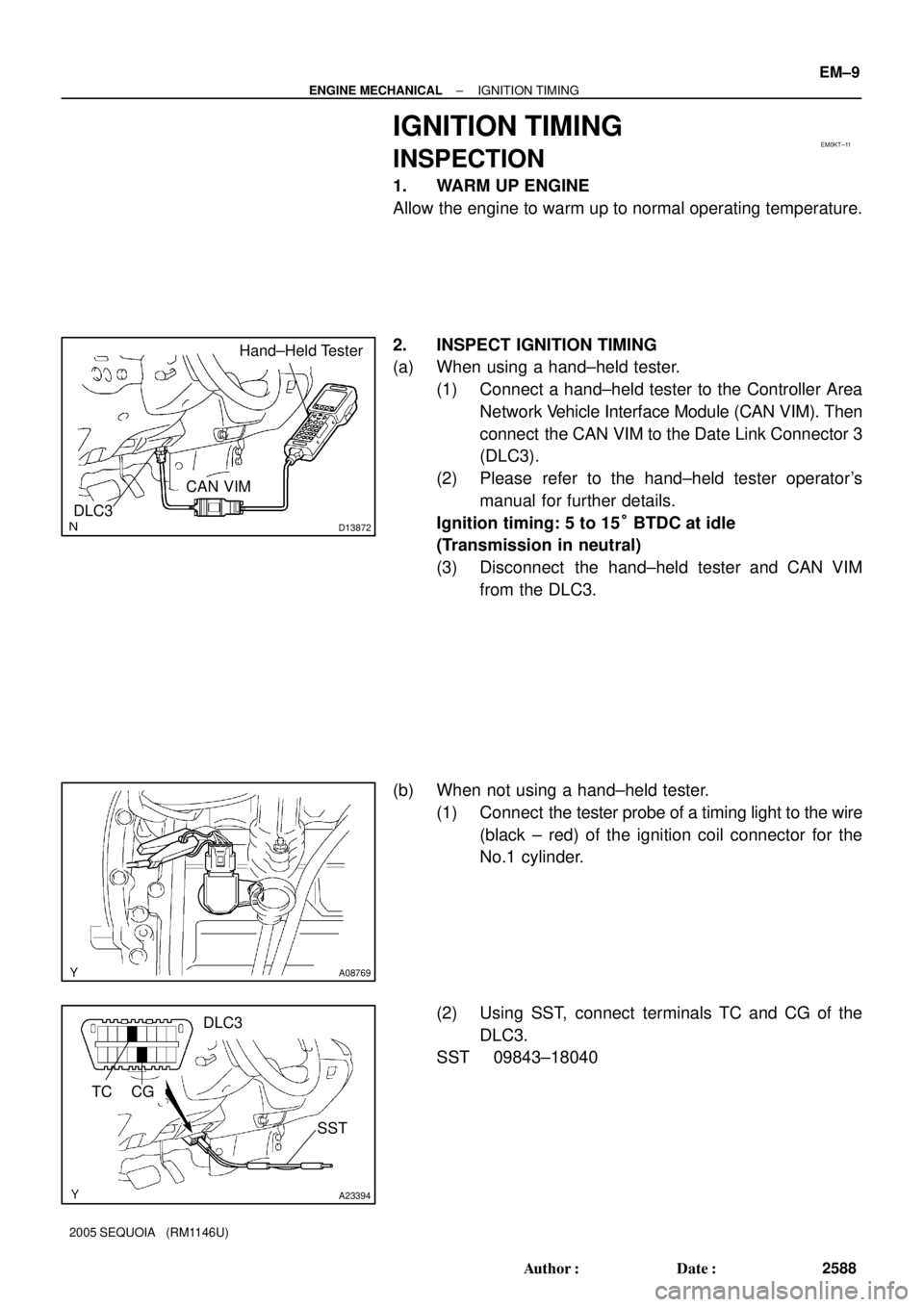
EM0KT±11
D13872
Hand±Held Tester
DLC3
CAN VIM
A08769
A23394
TC
SST
DLC3
CG
± ENGINE MECHANICALIGNITION TIMING
EM±9
2588 Author�: Date�:
2005 SEQUOIA (RM1146U)
IGNITION TIMING
INSPECTION
1. WARM UP ENGINE
Allow the engine to warm up to normal operating temperature.
2. INSPECT IGNITION TIMING
(a) When using a hand±held tester.
(1) Connect a hand±held tester to the Controller Area
Network Vehicle Interface Module (CAN VIM). Then
connect the CAN VIM to the Date Link Connector 3
(DLC3).
(2) Please refer to the hand±held tester operator's
manual for further details.
Ignition timing: 5 to 15° BTDC at idle
(Transmission in neutral)
(3) Disconnect the hand±held tester and CAN VIM
from the DLC3.
(b) When not using a hand±held tester.
(1) Connect the tester probe of a timing light to the wire
(black ± red) of the ignition coil connector for the
No.1 cylinder.
(2) Using SST, connect terminals TC and CG of the
DLC3.
SST 09843±18040
Page 2663 of 4323
A08928
ECM Connector ECM and Bracket AssemblyHeater to Register Dust
Lower No.2 Finish Panel
Glove Compartment Door
Wire Harness Connector (Cassette Connector)
A23366
Engine Wire Clamp
Engine WireHeater Hose Ground Strap
Fuel Inlet
HoseBattery
Negative
(±) Cable Heater Hose
Fuel Return
Hose
Generator Wire
Battery
Positive (+)
Terminal Clamp
Generator
Connector
EVAP Hose
w/o Hydraulic Brake Booster:
Brake Booster Tube
EM±76
± ENGINE MECHANICALENGINE UNIT (2WD)
2655 Author�: Date�:
2005 SEQUOIA (RM1146U)
Page 2666 of 4323

EM±79
2658 Author�: Date�:
2005 SEQUOIA (RM1146U)
REMOVAL
1. REMOVE ENGINE HOOD
2. REMOVE ENGINE UNDER COVER
3. DISCONNECT BATTERY")
EM120±07
B07536
Disconnect
± ENGINE MECHANICALENGINE UNIT (2WD)
EM±79
2658 Author�: Date�:
2005 SEQUOIA (RM1146U)
REMOVAL
1. REMOVE ENGINE HOOD
2. REMOVE ENGINE UNDER COVER
3. DISCONNECT BATTERY CABLES
(a) Disconnect the clamp on battery negative (±) cable from
the No.2 relay box.
(b) Disconnect the battery positive (+) terminal cable.
(c) Disconnect battery negative (±) cable from the left fender
apron.
4. DRAIN ENGINE COOLANT
5. REMOVE RADIATOR ASSEMBLY (See page CO±17)
6. REMOVE THROTTLE BODY COVER
7. REMOVE AIR CLEANER AND INTAKE AIR CONNEC-
TOR ASSEMBLY
(a) Disconnect the MAF meter connector.
(b) Loosen the 3 bolts, and remove the air cleaner case.
(c) Remove the suction hose from the intake air connector.
(d) Disconnect the PS air hose, air inlet hose for EVAP, PCV
hose and MAF meter wire from the air intake connector.
(e) Disconnect the intake air connector from the throttle body.
8. REMOVE DRIVE BELT, FAN, FLUID COUPLING AND
FAN PULLEY
(a) Loosen the 4 nuts holding the fluid coupling to the fan
bracket.
(b) Remove the drive belt. (See page CH±7)
(c) Remove the 4 nuts, the fan, fluid coupling assembly and
fan pulley.
9. DISCONNECT ENGINE WIRE FROM CABIN
(a) Remove the glove compartment door.
(b) Remove the lower No.2 panel.
(c) Remove the 3 screws, and disconnect the ECM from the
body bracket.
(d) Disconnect the 3 wire harness connectors from the ECM.
(e) Disconnect the 2 wire harness connectors (cassette con-
nector).
(f) Disconnect the engine wire from the engine wire bracket
and remove the bolt, 2 nuts and bracket.
(g) Pull out the engine wire from the cowl panel.
10. DISCONNECT HOSES, WIRES, CONNECTORS,
CLAMPS, GROMMET AND CABLES
(a) Disconnect the 2 PS air hoses from hose clamp on the
No.3 RH timing belt cover.
(b) Disconnect the generator wire.
(c) Disconnect the generator connector.
Page 2674 of 4323

EM±87
2666 Author�: Date�:
2005 SEQUOIA (RM1146U)
(b) Install the engine wire bracket with the 2 nuts and bolt and
connect the engine wire to t")
A09152
Connect
± ENGINE MECHANICALENGINE UNIT (2WD)
EM±87
2666 Author�: Date�:
2005 SEQUOIA (RM1146U)
(b) Install the engine wire bracket with the 2 nuts and bolt and
connect the engine wire to the bracket.
(c) Connect the 2 wire harness connectors (cassette con-
nector).
(d) Connect the 3 connectors to the ECM.
(e) Install the ECM with the 3 screws.
(f) Install the lower No.2 panel.
(g) Install the glove compartment door.
19. INSTALL FAN PULLEY, FAN, FLUID COUPLING AND
DRIVE BELT
(a) Temporarily install the fan pulley, the fan and fluid cou-
pling assembly with the 4 nuts.
(b) Install the drive belt. (See page CH±16)
(c) Tighten the 4 nuts holding the fluid coupling to the fan
bracket.
20. INSTALL AIR CLEANER AND INTAKE AIR CONNEC-
TOR ASSEMBLY
(a) Install the air cleaner with the 3 bolt.
Torque: 5.0 N´m (51 kgf´cm, 44 in.´lbf)
(b) Connect the intake air connector to the throttle body.
(c) Connect the MAF meter connector.
(d) Install the suction hose to the intake air connector.
(e) Connect the PS air hose, air inlet hose for EVAP, PCV
hose and MAF meter wire to the air intake connector.
21. INSTALL THROTTLE BODY COVER
22. INSTALL RADIATOR ASSEMBLY (See page CO±18)
23. INSTALL BATTERY CABLES
(a) Connect the clamp on battery negative (±) cable to No.2
relay box.
(b) Connect the battery positive (+) terminal cable.
(c) Connect the battery negative cable to the left fender
apron.
24. PERFORM INITIALIZATION
Some system need initialzation when disconnecting the cable
from the battery terminal.
25. FILL WITH ENGINE COOLANT (See page CO±2)
26. FILL WITH ENGINE OIL (See page LU±2)
27. START ENGINE AND CHECK FOR LEAKS
28. INSTALL ENGINE UNDER COVER
29. INSTALL HOOD
30. PERFORM ROAD TEST
Check for abnormal noise, shock, slippage, correct shift points
and smooth operation.
31. RECHECK ENGINE COOLANT AND OIL LEVELS
Page 2676 of 4323
A08928
ECM Connector ECM and Bracket AssemblyHeater to Register Dust
Lower No.2 Finish Panel
Glove Compartment Door
Wire Harness Connector (Cassette Connector)
A23366
Engine Wire Clamp
Engine WireHeater Hose Ground Strap
Fuel Inlet
HoseBattery
Negative
(±) Cable Heater Hose
Fuel Return
Hose
Generator Wire
Battery
Positive (+)
Terminal Clamp
Generator
Connector
EVAP Hose
w/o Hydraulic Brake Booster:
Brake Booster Tube
± ENGINE MECHANICALENGINE UNIT (4WD)
EM±89
2668 Author�: Date�:
2005 SEQUOIA (RM1146U)
Page 2679 of 4323

2671 Author�: Date�:
2005 SEQUOIA (RM1146U)
REMOVAL
1. REMOVE FRONT EXHAUST PIPES
(See page EM±126)
2. REMOVE FRONT AND REAR PROPELLER SHAFTS")
EM11X±07
EM±92
± ENGINE MECHANICALENGINE UNIT (4WD)
2671 Author�: Date�:
2005 SEQUOIA (RM1146U)
REMOVAL
1. REMOVE FRONT EXHAUST PIPES
(See page EM±126)
2. REMOVE FRONT AND REAR PROPELLER SHAFTS
(See page PR±7)
3. REMOVE FRONT STABILIZER BAR
(See page SA±91)
4. REMOVE TRANSMISSION (See page AT±25)
5. REMOVE ENGINE HOOD
6. REMOVE ENGINE UNDER COVER
7. DISCONNECT BATTERY CABLES
(a) Disconnect the clamp on battery negative (±) cable from
the No.2 relay box.
(b) Disconnect the battery positive (+) terminal cable.
(c) Disconnect the battery negative (±) cable from the left
fender apron.
8. DRAIN ENGINE COOLANT
9. REMOVE RADIATOR ASSEMBLY (See page CO±17)
10. REMOVE THROTTLE BODY COVER
11. REMOVE AIR CLEANER AND INTAKE AIR CONNEC-
TOR ASSEMBLY
(a) Disconnect the MAF meter connector.
(b) Loosen the 3 bolts, and remove the air cleaner case.
(c) Remove the suction hose from the intake air connector.
(d) Disconnect the PS air hose, air inlet hose for EVAP, PCV
hose and MAF meter wire from the air intake connector.
(e) Disconnect the intake air connector from the throttle body.
12. REMOVE DRIVE BELT, FAN, FLUID COUPLING AND
FAN PULLEY
(a) Loosen the 4 nuts holding the fluid coupling to the fan
bracket.
(b) Remove the drive belt. (See page CH±16)
(c) Remove the 4 nuts, the fan, fluid coupling assembly and
fan pulley.
13. DISCONNECT ENGINE WIRE FROM CABIN
(a) Remove the glove compartment door.
(b) Remove the lower No.2 panel.
(c) Remove the 3 screws, and disconnect the ECM from the
body bracket.
(d) Disconnect the 3 wire harness connectors from the ECM.
(e) Disconnect the 2 wire harness connectors (cassette con-
nector).


A23366
Engine Wire Clamp
Engine WireHeat")

A23366
Engine Wire Clamp
Engine WireHeat")