Page 1870 of 4323
DI277±14
I18700
J8
J/CB±R
2
L±WIG Instrument Panel J/B I18
Ignition SW
1IG1
AM1 B±Y4
1C
6
1CAM1
1 2ECU±IG
SUN ROOF1
1M
5
1M
1
1L8
5
B
W±L
B58 ALT F10
Fusible Link Block
W
Instrument Panel J/B
W±BW±B 7
1M 10
1F
IE Battery7
AS19
Sliding Roof
Control ECU
E DI±1668
± DIAGNOSTICSSLIDING ROOF SYSTEM
1862 Author�: Date�:
2005 SEQUOIA (RM1146U)
CIRCUIT INSPECTION
Power Source Circuit
CIRCUIT DESCRIPTION
This circuit provides power to operate the sliding roof control ECU.
WIRING DIAGRAM
Page 1872 of 4323
DI±1670
± DIAGNOSTICSSLIDING ROOF SYSTEM
1864 Author�: Date�:
2005 SEQUOIA (RM1146U)
2 Check voltage between terminals B, IG and GND of sliding roof control ECU con-
nector.
PREPARATION:
Turn ignition switch ON.
CHECK:
Measure voltage between terminals IG and GND.
OK:
Voltage: 10 to 14 V
PREPARATION:
(a) Turn ignition switch OFF.
(b) Disconnect the sliding roof control ECU connector.
CHECK:
Measure voltage between terminals B and GND.
OK:
Voltage: 10 to 14 V
OK Proceed to next circuit inspection shown on
problem symptom table (See page DI±1664).
NG
Repair or replace wire harness and connec-
tor.
Page 1873 of 4323
I18701
4
3
10
9 W±BS19
Sliding Roof
Control ECU
UP
DWN
CLS
OPN J8
J/CO59
O5 10
O512
O511 UP
DWN
CLS
OPN E O51
W±B1M7
1F10
IEAInstrument Panel J/BOverhead Module
R±Y
R±W
G±Y
P±B
± DIAGNOSTICSSLIDING ROOF SYSTEM
DI±1671
1865 Author�: Date�:
2005 SEQUOIA (RM1146U)
Sliding Roof Control Switch Circuit
CIRCUIT DESCRIPTION
The sliding roof control switch is built into the overhead module.
WIRING DIAGRAM
DI94F±05
Page 1876 of 4323
DI±1674
± DIAGNOSTICSSLIDING ROOF SYSTEM
1868 Author�: Date�:
2005 SEQUOIA (RM1146U)
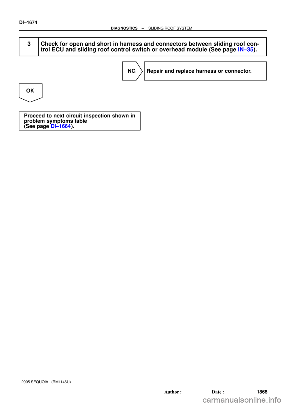
3 Check for open and short in harness and connectors between sliding roof con-
trol ECU and sliding roof control switch or overhead module (See page IN±35).
NG Repair and replace harness or connector.
OK
Proceed to next circuit inspection shown in
problem symptoms table
(See page DI±1664).
Page 1881 of 4323
DID98±01
I28587
From Battery Driving Position Memory Switch BODY ECU
Courtesy SW (D)
MM
Remote Control Mirror Switch
RHOuter
Mirror LH
(Retract
Motor) M1
M2 MM
M1 DCTY
PCTY
RRCY
RLCY
HCTY
KSW
LSWR
LSWL
PKB
WIG
IG
ACC
BECU
S+B
BDRACT+
ACTD
ACT±M2
MIRB
MIRS
MIRFM+
MSW
EB
MF
E2MR
Door Lock Motor
Front
LHFront
RHRear
LHRear
RH
Courtesy SW (P)
Courtesy SW (RR)
Courtesy SW (RL)
Hood Courtesy SW
Key Unlock Warning SW
Door Unlock Detection
SW Rear RH
Door Unlock Detection
SW Rear LH
Parking Brake SW
Battery AM1ALTACC IG1 Ignition SwitchWSH
ECU±IG
RAD No. 2
ECU±B
DOOR No. 2SECURITY
HORN AM1
± DIAGNOSTICSBODY CONTROL SYSTEM
DI±1679
1873 Author�: Date�:
2005 SEQUOIA (RM1146U)
SYSTEM DIAGRAM
Page 1882 of 4323
I28588
BEANBODY ECU
Hi Beam Indicator
Driver Door ECU
A/C ECU
Sliding Roof
Control ECUMPX1
MPX2
MPX3HIND
HRLY
H±ON
DIM
HEAD
TAIL
A
HF
HI
FOGCombination Meter
From
Battery
HEAD
MAIN
Headlight
DRL (*1)
Headlight
DRL No. 4H±LP(*2) DRLH±LP(*2)
Headlight
Headlight H±LP(*1)
H±LP(*1)
H±LP(*1)
H±LP(*1) DIMMER
(*2)
(*2) Combination Switch
Light Control
Switch
Dimmer
Switch
Fog Light
SwitchDRL
Resister
*1: w/ DRL
*2: w/o DRL DI±1680
± DIAGNOSTICSBODY CONTROL SYSTEM
1874 Author�: Date�:
2005 SEQUOIA (RM1146U)
Page 1883 of 4323
I28734
BODY ECU
Back Door
Power Window SW
Rear Wiper
and
Washer
Switch
Rear Washer
Motor
Theft Deterrent Horn
Light
Control
Sensor
Wireless
Door Lock
Receiver ECU±B From
Battery
DLC3From
Battery
POWER MAIN
Power
Window SW
(RR)Power
Window
Motor (RR)PWR
No. 3
PWR
No. 2
Power
Window SW
(RL)Power
Window
Motor (RL)
From
Battery
From
Battery DOME
HORN Interior Light
HORN
Vehicle Horn
Combination Meter
Security Indicator
Horn Switch
Glass
Breakage
Sensor ECUWireless Buzzer
ECU±B
HTR PWS
BUP
BDN
RWLS
RWC1
RWW
SHTRCY
RRU
RRD
RLU
RLD
ILE
CLTB
CLTS
CLTEHR
RDA
PRG
GND1IND
HORN
BZR
OBD2DOP
Microphone
From
Battery
± DIAGNOSTICSBODY CONTROL SYSTEM
DI±1681
1875 Author�: Date�:
2005 SEQUOIA (RM1146U)
Page 1884 of 4323
DI1OD±22
Customer Problem Analysis
Vehicle Brought to Workshop
Problem Symptom ConfirmationSymptom Simulation Symptom does not
occur
Circuit Inspection
Identification of Problem
Repair
Confirmation Test
EndTitles inside
are titles of pages in this
manual, with the page number indicated in
the bottom portion. See the indicated pages
for detailed explanations.
1
23
65
8P. IN±24 P. DI±1683
P. DI±1700 ± DI±1774
Symptom
occurs
Step 4, 6, 8: Diagnostic steps permitting the use of the hand±held tester. 7
Problem Symptoms Table
P. DI±1686
P. DI±1904
Multiplex communication system inspection * 4
*: Confirm that there is no trouble by DTC check.
DI±1682
± DIAGNOSTICSBODY CONTROL SYSTEM
1876 Author�: Date�:
2005 SEQUOIA (RM1146U)
HOW TO PROCEED WITH TROUBLESHOOTING
HINT:
This ECU is connected to the multiplex communication system. Therefore, be sure to check that there is no
troubles in the multiplex communication system before performing the troubleshooting.


MM
Remote Control Mirror Switch
RHOuter
Mirror LH
(Retract
Motor) M1
M2 MM
M1 DCTY
PCTY
RRCY
RLCY
HCTY
KSW
LSWR")


