Page 1792 of 4323
DI±1590
± DIAGNOSTICSENGINE IMMOBILISER SYSTEM
1784 Author�: Date�:
2005 SEQUOIA (RM1146U)
INSPECTION PROCEDURE
1 Check whether the engine can be started with the master key and sub±key for
another vehicle of the same type.
RESULT:
AAll keys start the engine.
BA specific key does not start the engine. In this case, DTC
21 or 22 is not stored in memory.
CAll keys do not start the engine. In this case, DTC 21 and 22
are not stored in memory.
A No problem at this time.
HINT:
If the result is ºAº, confirm whether or not the customer has ever
inserted the key (without a transponder chip) of another vehicle
into the ignition key cylinder.
B The transponder chip of a specific key is defec-
tive. Replace the key.
C
2 Check transponder key coil (See page BE±143).
NG Replace transponder key coil.
OK
3 Check harness and connector between transponder key ECU and transponder
key amplifier (See page IN±35).
NG Repair or replace harness or connector.
OK
Page 1793 of 4323
± DIAGNOSTICSENGINE IMMOBILISER SYSTEM
DI±1591
1785 Author�: Date�:
2005 SEQUOIA (RM1146U)
4 Does the system operate normally after replacement of transponder key ECU?
YES Replace transponder key ECU.
NO
Replace ECM (See page IN±35).
Page 1795 of 4323
I24830
ECMT16
Transponder Key ECU
IMI
IMO16
15P±G
11
10EFIO
EFII L±Y E5
E5
± DIAGNOSTICSENGINE IMMOBILISER SYSTEM
DI±1593
1787 Author�: Date�:
2005 SEQUOIA (RM1146U)
Code 32 or 33 is output
CIRCUIT DESCRIPTION
The transponder key ECU indicates DTC 32 when a key without a key code is inserted, and indicates DTC
33 when a key code cannot be identified.
HINT:
DTCs 32 and 33 are abnormal codes.
DTC No.DTC Detecting ConditionTrouble Area
32, 33Communication error
�Key
�Transponder key ECU
�Wire harness
WIRING DIAGRAM
DIABI±04
Page 1796 of 4323
DI±1594
± DIAGNOSTICSENGINE IMMOBILISER SYSTEM
1788 Author�: Date�:
2005 SEQUOIA (RM1146U)
INSPECTION PROCEDURE
1 Check whether the engine can be started with a spare key of the same vehicle.
YES Replace key.
NO
2 Check harness and connector between transponder key ECU and ECM (See
page IN±35).
NG Repair or replace harness or connector.
OK
3 Does the system operate normally after replacement of transponder key ECU?
YES Replace transponder key ECU.
NO
Replace ECM (See page IN±35).
Page 1797 of 4323
I24831
Transponder Key ECU
Sub J/B No. 3
+B
J43
J/C
51
O
BatteryF10
FL BlockW±R
B
4
IG BEngine Room J/B W±R32
1J
1E Instrument Panel J/B
A
AGND O14
T16 T16 1
2
W±R
3A 3B
81
2C
2D ECU±B
SHORT PIN
± DIAGNOSTICSENGINE IMMOBILISER SYSTEM
DI±1595
1789 Author�: Date�:
2005 SEQUOIA (RM1146U)
Power source circuit
CIRCUIT DESCRIPTION
This circuit provides power to operate the transponder key ECU.
WIRING DIAGRAM
DI7TO±07
Page 1798 of 4323
DI±1596
± DIAGNOSTICSENGINE IMMOBILISER SYSTEM
1790 Author�: Date�:
2005 SEQUOIA (RM1146U)
INSPECTION PROCEDURE
1 Check ECU±B fuse.
CHECK:
Check for continuity of the ECU±B fuse.
OK:
Continuity
NG Replace fuse.
OK
2 Check voltage between terminals +B and GND of transponder key ECU connec-
tor.
PREPARATION:
(a) Turn the ignition switch OFF.
(b) Disconnect the transponder key ECU connector.
CHECK:
Measure the voltage between terminals +B and GND.
OK:
Voltage: 10 to 14 V
OK Proceed to next circuit inspection shown in
problem symptoms table (See page DI±1573).
NG
3 Check wire harness and connector between terminal GND of transponder key
ECU and body ground (See page IN±35).
NG Repair or replace wire harness or connector.
OK
Check and repair wire harness and connec-
tor between transponder key ECU and bat-
tery.
Page 1799 of 4323
I24835
Instrument Panel J/B
6 9
BR
1F 1D W±B
A
IEJ8
J/C12
C6C516
LG±B7
T16IND Combination MeterTransponder Key ECU
Security
± DIAGNOSTICSENGINE IMMOBILISER SYSTEM
DI±1597
1791 Author�: Date�:
2005 SEQUOIA (RM1146U)
Security Indicator Light Circuit
CIRCUIT DESCRIPTION
When the transponder key is registered, the transponder key ECU outputs the key registration condition by
illuminating, blinking or turning off the security indicator.
WIRING DIAGRAM
DIABJ±03
Page 1800 of 4323
I24836
ON
IND
(±) (+)
DI±1598
± DIAGNOSTICSENGINE IMMOBILISER SYSTEM
1792 Author�: Date�:
2005 SEQUOIA (RM1146U)
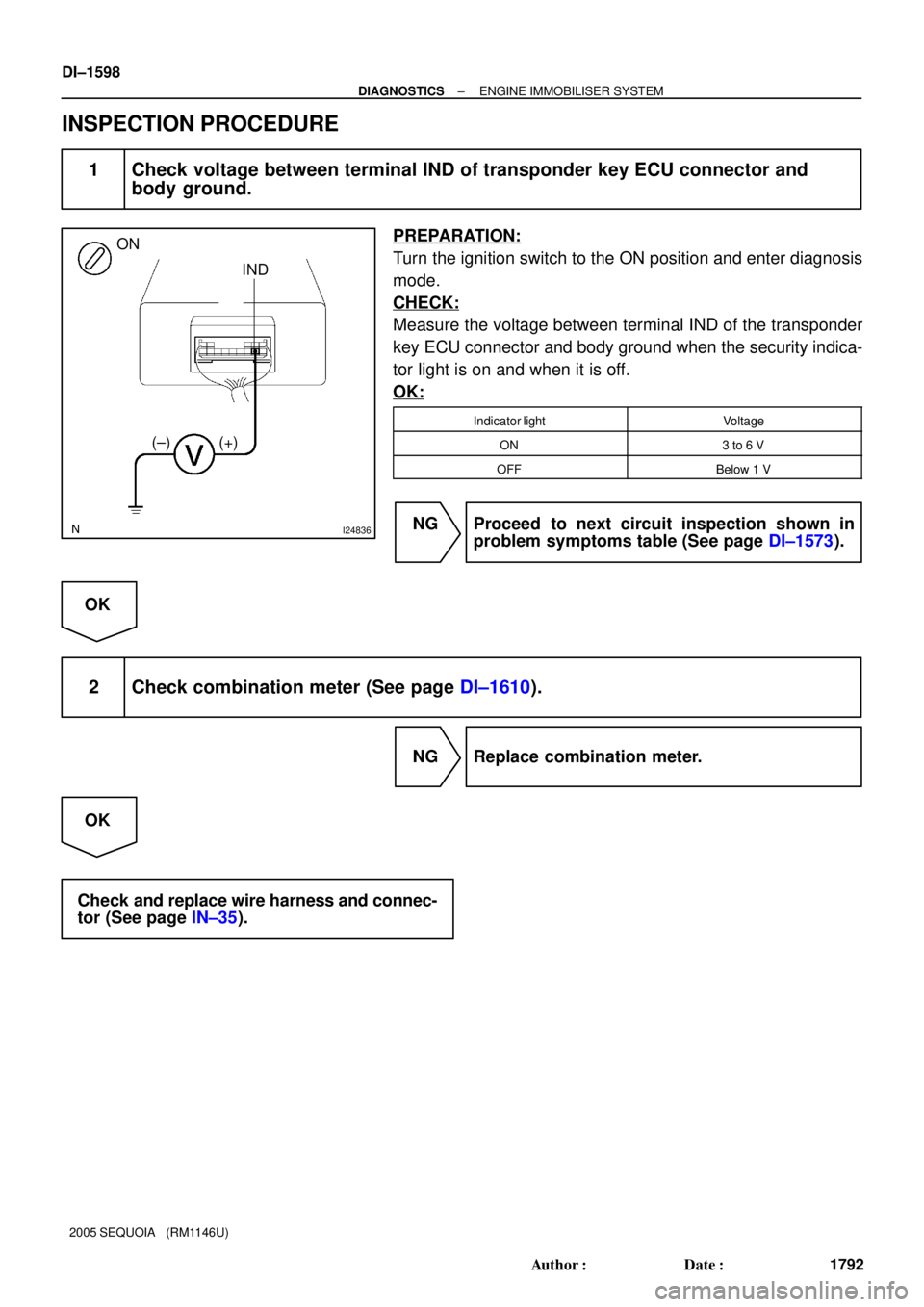
INSPECTION PROCEDURE
1 Check voltage between terminal IND of transponder key ECU connector and
body ground.
PREPARATION:
Turn the ignition switch to the ON position and enter diagnosis
mode.
CHECK:
Measure the voltage between terminal IND of the transponder
key ECU connector and body ground when the security indica-
tor light is on and when it is off.
OK:
Indicator lightVoltage
ON3 to 6 V
OFFBelow 1 V
NG Proceed to next circuit inspection shown in
problem symptoms table (See page DI±1573).
OK
2 Check combination meter (See page DI±1610).
NG Replace combination meter.
OK
Check and replace wire harness and connec-
tor (See page IN±35).