Page 1909 of 4323

INSPECTION PROCEDURE
HINT:
When using the hand±held tester, start the inspection from step 1 and when not usin")
± DIAGNOSTICSBODY CONTROL SYSTEM
DI±1707
1901 Author�: Date�:
2005 SEQUOIA (RM1146U)
INSPECTION PROCEDURE
HINT:
When using the hand±held tester, start the inspection from step 1 and when not using the hand±held tester,
start from step 2.
1 Check TAILLIGHT relay using hand±held tester.
PREPARATION:
(a) Connect the hand±held tester to the DLC3.
(b) Turn the ignition switch ON.
CHECK:
According to the display on the tester, perform the ºACTIVE TESTº.
BODY ECU:
ItemTest DetailsDiagnostic Note
TAIL LIGHTTaillight ON/OFF±
OK:
The taillights turn on or off correctly when operating them through the hand±held tester.
OK Proceed to next circuit inspection shown in
problem symptoms table (See page DI±1686).
NG
2 Check TAILLIGHT relay (See page BE±27).
NG Replace TAILLIGHT relay.
OK
3 Check wire harness and connector between TAILLIGHT relay and body ECU, bat-
tery and TAILLIGHT relay (See page IN±35).
NG Repair or replace wire harness or connector.
OK
Proceed to next circuit inspection shown in
problem symptoms table
(See page DI±1686).
Page 1910 of 4323
: w/ Daytime Running Light
(*2): w/o Daytime Runn")
I24144
Body ECU
MAINEngine Room J/B
HEAD Relay
Instrument Panel J/B
Battery
LG±R 2D
B12FL
R±W
12 532F
2G
2C
B7 1G 1JL
R±L
R±L
HRLY 8
6
1
6
1
2
(*1): w/ Daytime Running Light
(*2): w/o Daytime Running LightLG±R69 8 To Headlight RH To Headlight LH To DRL No.4 Relay To DIMMER Relay To DIMMER Relay
B 4
5 F10
FL Block(*2) (*2) (*1)
(*1)
(*1)
H±LP RH (*2)
DRL (*1)
H±LP LH (*2)
(*1) DI±1708
± DIAGNOSTICSBODY CONTROL SYSTEM
1902 Author�: Date�:
2005 SEQUOIA (RM1146U)
Headlight Relay Circuit
CIRCUIT DESCRIPTION
HEAD relay will be ºONº by operating the light control switch. The transistor which activates the HEAD relay
has two sorts: one is activated by the light control switch for fail safe and the other is activated by CPU. The
one that is activated by CPU prevents the headlight from turning off at the time of trouble with the other sys-
tem in the automatic operation circuit.
When the theft deterrent system is activated, it causes the transistor in the ECU to switch ON and OFF at
approximately 0.25 sec. intervals. This switches the HEAD relay ON and OFF, and thus flashing the head-
lights (See the wiring diagram below).
In this condition, if any of the following operations is done, the transistor in the ECU goes OFF and the HEAD
control relay switches OFF, and thus stopping the headlights flashing:
(1) Unlock the front LH or RH door with a key.
(2) Turn the ignition switch to ACC or ON position.
(3) Unlock the doors with the wireless door lock control system.
(4) Wait for approximately 60 seconds.
WIRING DIAGRAM
DI5VQ±14
Page 1911 of 4323

INSPECTION PROCEDURE
HINT:
When using the hand±held tester, start the inspection from step 1 and when not usin")
± DIAGNOSTICSBODY CONTROL SYSTEM
DI±1709
1903 Author�: Date�:
2005 SEQUOIA (RM1146U)
INSPECTION PROCEDURE
HINT:
When using the hand±held tester, start the inspection from step 1 and when not using the hand±held tester,
start from step 2.
1 Check HEAD relay using hand±held tester.
PREPARATION:
(a) Connect the hand±held tester to the DLC3.
(b) Turn the ignition switch ON.
CHECK:
According to the display on the tester, perform the ºACTIVE TESTº.
BODY ECU:
ItemTest DetailsDiagnostic Note
HEAD LIGHTHeadlight relay ON/OFF±
OK:
The headlights turn on or off correctly when operating them through the hand±held tester.
OK Proceed to next circuit inspection shown in
problem symptoms table (See page DI±1686).
NG
2 Check HEAD relay (See page BE±27).
NG Replace HEAD relay.
OK
3 Check wire harness and connector between HEAD relay and body ECU, battery
and HEAD relay (See page IN±35).
NG Repair or replace wire harness or connector.
OK
Proceed to next circuit inspection shown in
problem symptoms table
(See page DI±1686).
Page 1912 of 4323
I28516
J5
J/CBody ECU
FFOG J50
J/C J3
J/C
5 Instrument Panel J/B
From DIMMER Relay (*1) FOG LIGHT Relay
FOG
1K7
1B9
1J10 1L1
3
1 2 D
D
D
1
2F2
Front Fog
Light RH
W±B
B 1
2P
W±B
EDIGALTF10
FL Block 8
5
B
BatteryR±W
C8 Combination Switch
� Fog Light Switch
B613
G±B
10
LFG BFG 11 P
F1
Front Fog
Light LH
G±W (*1)
Y±R (*2) WP
A
(*1): w/ Daytime Running Light
(*2): w/o Daytime Running LightB
J2
J/C B
BW±B
J18
J/C W±B W±B
IL1
From Headlight (*2) 16
A DI±1710
± DIAGNOSTICSBODY CONTROL SYSTEM
1904 Author�: Date�:
2005 SEQUOIA (RM1146U)
Front fog light relay and switch circuit
CIRCUIT DESCRIPTION
The fog light switch is built into the combination switch.
Turning the fog light switch ON supplies power to terminal FFOG of the body ECU.
The fog lights come on when the FOG light relay is turned on.
WIRING DIAGRAM
DI6U4±14
Page 1913 of 4323
± DIAGNOSTICSBODY CONTROL SYSTEM
DI±1711
1905 Author�: Date�:
2005 SEQUOIA (RM1146U)
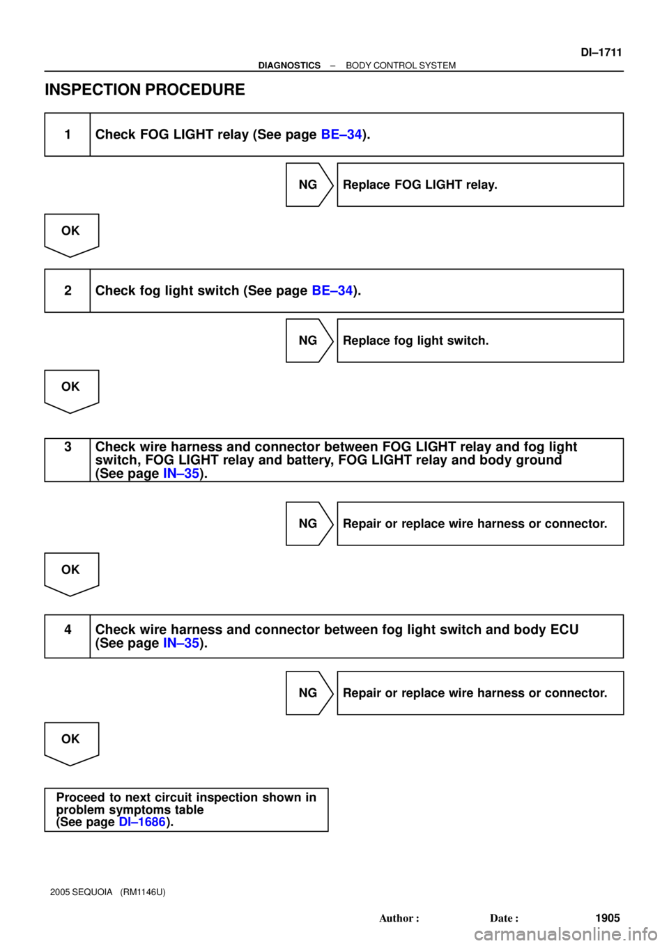
INSPECTION PROCEDURE
1 Check FOG LIGHT relay (See page BE±34).
NG Replace FOG LIGHT relay.
OK
2 Check fog light switch (See page BE±34).
NG Replace fog light switch.
OK
3 Check wire harness and connector between FOG LIGHT relay and fog light
switch, FOG LIGHT relay and battery, FOG LIGHT relay and body ground
(See page IN±35).
NG Repair or replace wire harness or connector.
OK
4 Check wire harness and connector between fog light switch and body ECU
(See page IN±35).
NG Repair or replace wire harness or connector.
OK
Proceed to next circuit inspection shown in
problem symptoms table
(See page DI±1686).
Page 1914 of 4323
DI±1712
± DIAGNOSTICSBODY CONTROL SYSTEM
1906 Author�: Date�:
2005 SEQUOIA (RM1146U)
Daytime running light relay circuit
CIRCUIT DESCRIPTION
Power is supplied to the DIMMER and DRL No. 4 relays when the HEAD relay is turned on.
The HEAD relay turns on by turning the light control switch to the TAIL or HEAD position.
The DIMMER relay turns on by turning the headlight dimmer switch to the LOW, HIGH, or FLASH position.
The body ECU determines the light control switch position and turns on the DRL No. 4 and DIMMER relays.
The DRL No. 4 relay and the daytime running light resistor are parallel circuits. If the light control switch is
OFF, electric current flows to body ground via the resistor instead of driving the DRL No. 4 relay. The head-
lights come on and dim according to the amount of resistance.
DI6M3±11
Page 1915 of 4323
I28771
32
2
1
2Body ECU
2
2 L1
G±W2
2 2
Engine Room R/B No. 2R±W
21
21
21 R±L
A
To Body ECU
(HEAD Relay Circuit)B7
R
2F
B 5
EDMAINHEAD RelayDRLIA117
Battery F10
FL Block J1
J/CW±L
W±L
R±L
R±W
R±WW±B G±W
32
1 W±LW
12 A
A
A
2
22
2
12 3
5
B7 W±B
R W±B
R±LL
L 5
3
21
53
12 12 12G
2C 2D16
4 A2
22
2
2 DIMMER Relay Engine Room R/B No. 2 H5
Headlight
LH
16
17 CH±LP RH
H±ON
DIM DRL No. 4 Relay J4
J/CC H6
Headlight RH
H±LP LH
H±LP RL
H±LP LL
IA118 W±B
4Engine Room R/B No. 2
Engine Room J/B
6
LG±R R±B
J2 J/C
W±L
D1 Daytime Running
Light Resistor
J5
J/C
A
EA
± DIAGNOSTICSBODY CONTROL SYSTEM
DI±1713
1907 Author�: Date�:
2005 SEQUOIA (RM1146U)
WIRING DIAGRAM
Page 1917 of 4323
I24352
Body ECU
B5KSW
IGU1
Key Unlock Warning Switch
O1
2
Y±G13
A
AJ43
J/C
O
± DIAGNOSTICSBODY CONTROL SYSTEM
DI±1715
1909 Author�: Date�:
2005 SEQUOIA (RM1146U)
Key unlock warning switch circuit
CIRCUIT DESCRIPTION
The key unlock warning switch turns on when the ignition key is inserted into the key cylinder and turns off
when the key is removed.
WIRING DIAGRAM
DI571±11
 FOG LIGHT Relay
FOG
1K7
1B9
1J10 1L1
3
1 2 D
D
D
1
2F2
Front Fog
Light RH
W±B
B 1
2P
W±B
EDIGALTF10
FL Block 8")

B7
R
2F
B 5
EDMAINHEAD RelayDRLIA117
Battery F10
FL Block J1
J/CW±L
W±L
R±L
R±W
R")