Page 1858 of 4323

2 Read value of hand±held tester.
PREPARATION:
(a) Connect the hand±held tester to the DLC3.
(b)")
I01278
DI±1656
± DIAGNOSTICSCOMBINATION METER SYSTEM
1850 Author�: Date�:
2005 SEQUOIA (RM1146U)
2 Read value of hand±held tester.
PREPARATION:
(a) Connect the hand±held tester to the DLC3.
(b) Turn the ignition switch ON, and push the hand±held tester main switch ON.
CHECK:
Operate the hand±held tester according to the steps on the display and select ºDATA LISTº.
METER:
ItemMeasurement Item /
Range (Display)Normal ConditionDiagnostic Note
OIL GAUGEOil Gauge /
Min.: 0 Max.: 255Tester indication changes accord-
ing to the oil pressure receiver
gauge angle.
OK:
Oil pressure displayed on the tester is almost the same as the actual oil pressure.
OK Replace combination meter.
(See page IN±35)
NG
3 Inspect oil pressure sender gauge.
PREPARATION:
Disconnect the connector from the oil pressure sender.
CHECK:
(a) Check that no continuity exists between the terminal and
ground with the engine stopped.
(b) Check that continuity exists between the terminal and
ground with the engine running.
HINT:
Oil pressure should be over 24.5 kPa (0.25 kgf/cm
2, 3.55 psi).
OK:
When engine is stopped:
No continuity
When engine is running:
Continuity
NG Replace oil pressure sender gauge.
OK
Page 1861 of 4323

INSPECTION PROCEDURE
HINT:
Start the inspection from step 1 when using the hand±held tester and start fro")
± DIAGNOSTICSCOMBINATION METER SYSTEM
DI±1659
1853 Author�: Date�:
2005 SEQUOIA (RM1146U)
INSPECTION PROCEDURE
HINT:
Start the inspection from step 1 when using the hand±held tester and start from step 2 when not using the
hand±held tester.
1 Perform active test by hand±held tester.
PREPARATION:
(a) Connect the hand±held tester to the DLC3.
(b) Turn the ignition switch ON, and push the hand±held tester main switch ON.
CHECK:
From the display on the tester, perform the ºACTIVE TESTº.
METER:
ItemTest DetailsDiagnostic Note
VOLT METER9 V / 12 V / 15 V / 18VConfirm that the vehicle is stopped and engine is
idling.
OK:
Volt meter readings change according to hand±held tester operation.
NG Replace combination meter
(See page IN±35).
OK
2 Check fuse.
CHECK:
Measure the resistance of the IGN1 fuse in the instrument panel J/B.
OK:
Below 1 W
CHECK:
Measure the resistance of the AM2 fuse in the engine room J/B.
OK:
Below 1 W
NG Inspect for short circuit in harness and all com-
ponents connected to fuse.
OK
Page 1928 of 4323

2 (±)
DI±1726
± DIAGNOSTICSBODY CONTROL SYSTEM
1920 Author�: Date�:
2005 SEQUOIA (RM1146U)
INSPECTION PROCEDURE
HINT:
When using the hand±held tester, start the inspection from step")
I00298
1 (+)
2 (±)
DI±1726
± DIAGNOSTICSBODY CONTROL SYSTEM
1920 Author�: Date�:
2005 SEQUOIA (RM1146U)
INSPECTION PROCEDURE
HINT:
When using the hand±held tester, start the inspection from step 1 and when not using the hand±held tester,
start from step 2.
1 Check engine hood courtesy switch using hand±held tester.
PREPARATION:
(a) Connect the hand±held tester to the DLC3.
(b) Turn the ignition switch ON.
CHECK:
According to the display on the tester, read the ºDATA LISTº.
BODY ECU:
ItemMeasurement Item/Display
(Range)Normal ConditionDiagnostic Note
HOOD COURTSY SWHood courtesy switch/ON or OFF
ON: Engine hood OPEN
(Hood courtesy switch ON)
OFF: Engine hood CLOSE
(Hood courtesy switch OFF)
±
OK:
The indication on the tester switches between ON and OFF in accordance with the engine hood
courtesy switch status.
OK Proceed to next circuit inspection shown in
problem symptoms table (See page DI±1686).
NG
2 Check engine hood courtesy switch.
PREPARATION:
Disconnect the engine hood courtesy switch connector.
CHECK:
Check continuity between terminals 1 and 2 when the engine
hood lock is locked and unlocked.
OK:
Engine hood lock
conditionTester connectionSpecified condition
LOCK1 ± 2No continuity
UNLOCK1 ± 2Continuity
NG Replace engine hood courtesy switch.
OK
Page 1939 of 4323
I24356
32
1J 1E W±RBody ECU
RDA ECU±B
4
52D
5
4
B5PRG B
OW±R
B5 5
IG1
BatterySHORT PIN Engine Room J/B
1
2C8
Sub J/B No. 3
3A2
3A1
RDA PRG W2
Wireless Door
Control Receiver
+B
EV
R±G 3
2 W±RInstrument Panel J/B
F10
Fusible
Link
Block
BW±R
A J43
J/C
O
A
± DIAGNOSTICSBODY CONTROL SYSTEM
DI±1737
1931 Author�: Date�:
2005 SEQUOIA (RM1146U)
Wireless door lock receiver circuit
CIRCUIT DESCRIPTION
The signal from the transmitter is sent to the body ECU through RDA line of the wireless door control receiver.
RDA line is diagnosed by the body ECU, check DTC also in case of the failure of the wireless function.
WIRING DIAGRAM
DI6LV±13
Page 1964 of 4323
DI±1762
± DIAGNOSTICSBODY CONTROL SYSTEM
1956 Author�: Date�:
2005 SEQUOIA (RM1146U)
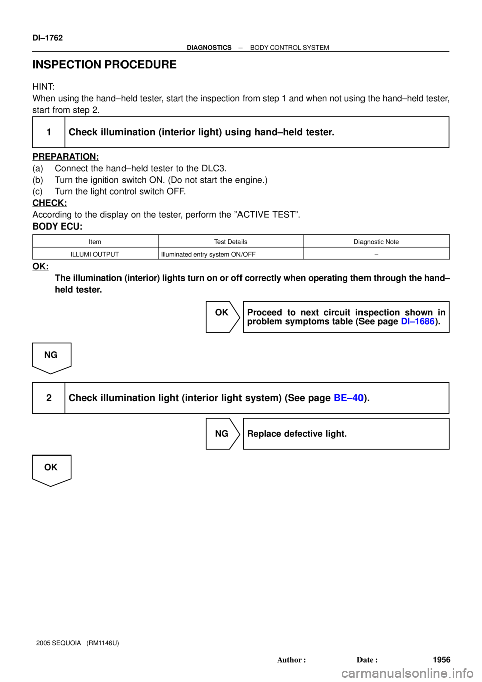
INSPECTION PROCEDURE
HINT:
When using the hand±held tester, start the inspection from step 1 and when not using the hand±held tester,
start from step 2.
1 Check illumination (interior light) using hand±held tester.
PREPARATION:
(a) Connect the hand±held tester to the DLC3.
(b) Turn the ignition switch ON. (Do not start the engine.)
(c) Turn the light control switch OFF.
CHECK:
According to the display on the tester, perform the ºACTIVE TESTº.
BODY ECU:
ItemTest DetailsDiagnostic Note
ILLUMI OUTPUTIlluminated entry system ON/OFF±
OK:
The illumination (interior) lights turn on or off correctly when operating them through the hand±
held tester.
OK Proceed to next circuit inspection shown in
problem symptoms table (See page DI±1686).
NG
2 Check illumination light (interior light system) (See page BE±40).
NG Replace defective light.
OK
Page 2147 of 4323

INSPECTION PROCEDURE
1 Check combination meter.
CHECK:
Start the engine and check that the speed met")
± DIAGNOSTICSMULTIPLEX COMMUNICATION SYSTEM
DI±1945
2139 Author�: Date�:
2005 SEQUOIA (RM1146U)
INSPECTION PROCEDURE
1 Check combination meter.
CHECK:
Start the engine and check that the speed meter and tachometer operate normally.
HINT:
With this inspection, the combination meter CPU can be diagnosed if it works normally or not.
OK:
Speed meter and tachometer operate normally.
NG Go to combination system (See page DI±1610).
OK
2 Check wire harness and connector (Combination meter ± back door ECU, com-
bination meter ± integration control and panel).
PREPARATION:
Disconnect connector ºB11º of the back door ECU, connector ºC5º of the combination meter and connector
ºI19º of the integration control and panel.
CHECK:
Measure the resistance according to the values in the table below.
OK:
Tester connection (Symbols)ConditionSpecified condition
B11±2 (MPX1) ± C5±31AlwaysBelow 1 W
I19±13 (MPX±) ± C5±32AlwaysBelow 1 W
B11±2 (MPX1) ± Body groundAlways10 kW or higher
I19±13 (MPX±) ± Body groundAlways10 kW or higher
NG Repair or replace wire harness.
OK
Replace the combination meter.
If the problem recurs even after replacement, replace the body ECU.
Page 2168 of 4323

5. Identify the condition in which the noise occurs, and check the noise filter on the related part.
Condition in whic")
DI±1966
± DIAGNOSTICSAUDIO SYSTEM
2160 Author�: Date�:
2005 SEQUOIA (RM1146U)
5. Identify the condition in which the noise occurs, and check the noise filter on the related part.
Condition in which noise occursNoise Source
Depressing the acceleration pedal increases the noise, and stopping the
engine stops the noise immediately.Generator
Noise occurs during A/C or the heater operation.Blower motor
Rapid acceleration while driving on an unpaved road or after the ignition
switch is turned on makes noise.Fuel pump
Pressing and then releasing the horn switch, and keeping pressing the horn
switch makes unusual noise.Horn
Quiet noise is heard while the engine is running, but stops with the engine.Ignition
Noise occurs synchronously with the turn signal flash.Flasher
Noise occurs during window washer operation.Washer
Noise occurs while the engine is running, and it continues even after the en-
gine stops.Engine coolant temperature sensor
Noise occurs during wiper operation.Wiper
Noise occurs when the brake pedal is depressed.Stop light switch
Others.Static electricity stored on the vehicle
Reference:
�Make sure first that there is no noise from outside. Failing to do so makes the noise source detec-
tion difficult and leads to misdiagnosis.
�The noise should be removed in descending order of loudness.
�Tuning the radio so that no station is received wakes the noise more noticeable, making the rec-
ognition of the phenomenon easier.
Page 2181 of 4323

DIAGNOSTIC TROUBLE CODE CHART
TermsMeaning
Physical addressThree±digit code (shown in hexadecimal) which is")
DID9T±01
± DIAGNOSTICSAUDIO SYSTEM
DI±1979
2173 Author�: Date�:
2005 SEQUOIA (RM1146U)
DIAGNOSTIC TROUBLE CODE CHART
TermsMeaning
Physical addressThree±digit code (shown in hexadecimal) which is given to each component com-
prising the AVC±LAN.
Corresponding to the function, individual symbols are specified.
Logical addressTwo±digit code (shown in hexadecimal) which is given to each function comprising
the inner system of the AVC±LAN.
HINT:
Titles for each unit are stated in the following order: parts name (physical address) and [Name indicated on
the DTC display]
1. Radio receiver assy (physical address: 190) [AUDIO H/U]
(a) Logical address: 01 (Communication control)
DTCNameDiagnosisVerificationSee page
D6
*1Absence of Master
Component in which this code is recorded was
disconnected from system or master component
with ignition switch in ACC or ON.
1. Power source circuit (Stereo
component amplifier assy).
2. Power source circuit (Rear seat
audio controller). *6
3. Power source circuit (Multi±dis-
play controller sub±assy) *7
4. AVC±LAN circuit (Radio receiver
assy ± Stereo component ampli-
fier assy).
5. AVC±LAN (Radio receiver assy
± Rear seat audio controller). *6
6. AVC±LAN (Radio receiver assy
± Multi±display controller sub±
assy). *7
7. Replace stereo component am-
plifier assy.
8. Replace rear seat audio control-
ler. *6
9. Replace multi±display controller
sub±assy. *7DI±1993
DI±2058
DI±2110
DI±2023
DI±2061
DI±2139
±
±
±
D8
*2
*5No Response to Connection
CheckComponent shown by sub code is or was discon-
nected from system after engine start.
1. Power source circuit (Stereo
component amplifier assy).
2. Power source circuit (Rear seat
audio controller). *6
3. Power source circuit (Multi±dis-
play controller sub±assy) *7
4. AVC±LAN circuit (Radio receiver
assy ± Stereo component ampli-
fier assy).
5. AVC±LAN (Radio receiver assy
± Rear seat audio controller). *6
6. AVC±LAN (Radio receiver assy
± Multi±display controller sub±
assy). *7
7. Replace stereo component am-
plifier assy.
8. Replace rear seat audio control-
ler. *6
9. Replace multi±display controller
sub±assy. *7DI±1993
DI±2058
DI±2110
DI±2023
DI±2061
DI±2139
±
±
±