Page 1406 of 4323

H02750
O6
Occupant Classification ECU
FSR+
BL13
WW
A2116Airbag Sensor Assembly
A2124
B B
BL15
FSR±FSR+
FSR± 8
4 DI±1204
± DIAGNOSTICSSUPPLEMENTAL RESTRAINT SYSTEM
1398 Author�: Date�:
2005 SEQUOIA (RM1146U)
DTC B1650/32 Occupant Classification System
Malfunction
CIRCUIT DESCRIPTION
The occupant classification system circuit consists of the airbag sensor assembly and the occupant classifi-
cation system.
If the airbag sensor assembly receives signals from the occupant classification ECU, it determines whether
or not the front passenger airbag assembly, side airbag assembly RH and seat belt pretensioner RH should
be operated.
DTC B1650/32 is recorded when a malfunction is detected in the occupant classification system circuit.
DTC No.DTC Detecting ConditionTrouble Area
B1650/32
�Occupant classification system malfunction
�The airbag sensor assembly receives a line short circuit
signal, an open circuit signal, a short circuit to ground sig-
nal or a short circuit to B+ signal in the occupant classifi-
cation system circuit for 2 seconds.
�Airbag sensor assembly malfunction
�Occupant classification system
�Airbag sensor assembly
�Floor wire
�Seat wire No. 1
WIRING DIAGRAM
DIDGY±01
Page 1407 of 4323

H10600H01065H08008
H24037
Airbag
Sensor
Assembly
DLC3
CG TCOccupant
Classification ECU
DTC B1650/32
± DIAGNOSTICSSUPPLEMENTAL RESTRAINT SYSTEM
DI±1205
1399 Author�: Date�:
2005 SEQUOIA (RM1146U)
INSPECTION PROCEDURE
1 Check DTC (occupant classification ECU).
CHECK:
(a) Turn the ignition switch to the ON position, and wait for at least 10 seconds.
(b) Using the hand±held tester, check the DTCs of the occupant classification ECU (see page DI±1147).
OK:
DTC is not output of the occupant classification ECU.
NG Go to inspection procedure of DTC output
(see page DI±1155).
OK
2 Check DTC (airbag sensor assembly).
CHECK:
(a) Turn the ignition switch to the ON position, and wait for at
least 60 seconds.
(b) Clear the DTCs stored in memory (see page DI±1147).
HINT:
First clear DTCs stored in the occupant classification ECU and
then in the airbag sensor assembly.
(c) Turn the ignition switch to the LOCK position.
(d) Turn the ignition switch to the ON position, and wait for at
least 60 seconds.
(e) Check the DTCs (see page DI±1147).
OK:
DTC B1650/32 is not output.
HINT:
Codes other than DTC B1650/32 may be output at this time, but
they are not related to this check.
NG Go to step 3.
OK
From the results of the above inspection, the malfunctioning part can now be considered normal.
To make sure of this, use the simulation method to check (see page DI±1137).
Page 1408 of 4323

3 Check connection of connectors.
PREPARATION:
(a) Turn the ignition switch to the LOCK position.
(b)")
DI±1206
± DIAGNOSTICSSUPPLEMENTAL RESTRAINT SYSTEM
1400 Author�: Date�:
2005 SEQUOIA (RM1146U)
3 Check connection of connectors.
PREPARATION:
(a) Turn the ignition switch to the LOCK position.
(b) Disconnect the negative (±) terminal cable from the battery, and wait for at least 90 seconds.
CHECK:
Check that the connectors are properly connected to the airbag sensor assembly and the occupant classifi-
cation ECU.
OK:
The connectors are connected securely.
NG Connect connectors, then go to step 1.
OK
4 Prepare for inspection.
CAUTION:
Be sure to perform the following procedures before troubleshooting to avoid unexpected airbag de-
ployment.
(a) Disconnect the connectors from the airbag sensor assembly.
(b) Disconnect the connectors from the steering wheel pad.
(c) Disconnect the connectors from the front passenger airbag assembly.
(d) w/ Side and curtain shield airbag:
Disconnect the connectors from the side airbag assembly LH and RH.
(e) w/ Side and curtain shield airbag:
Disconnect the connectors from the curtain shield airbag assembly LH and RH.
(f) Disconnect the connectors from the front seat outer belt LH and RH.
NEXT
Page 1409 of 4323

C84207G27650H43694H24002
Occupant
Classification ECUAirbag
Sensor
Assembly
D
FSR±FSR+ CBA
FSR+
FSR± O6
E F
A21
Service Wire
C84205G27650H24003
Occupant
Classification ECUAirbag
Sensor
Assembly
D
A21
FSR±FSR+CBA
E F
± DIAGNOSTICSSUPPLEMENTAL RESTRAINT SYSTEM
DI±1207
1401 Author�: Date�:
2005 SEQUOIA (RM1146U)
5 Check occupant classification system circuit (open).
PREPARATION:
(a) Disconnect the connector from the occupant classifica-
tion ECU.
(b) Using a service wire, connect O6±8 (FSR+) and O6±4
(FSR±) of connector ºEº.
NOTICE:
Do not forcibly insert a service wire into the terminals of the
connector when connecting.
CHECK:
Measure the resistance according to the value(s) in the table
below.
OK:
Tester ConnectionConditionSpecified Condition
A21±16 (FSR+) ±
A21±24 (FSR±)AlwaysBelow 1 W
NG Go to step 9.
OK
6 Check occupant classification system circuit (short).
PREPARATION:
Disconnect the service wire from connector ºEº.
CHECK:
Measure the resistance according to the value(s) in the table
below.
OK:
Tester ConnectionConditionSpecified Condition
A21±16 (FSR+) ±
A21±24 (FSR±)Always1 MW or higher
NG Go to step 10.
OK
Page 1410 of 4323
C84205G27650H24003
Occupant
Classification ECUAirbag
Sensor
Assembly
D
A21
FSR±FSR+CBA
E F
DI±1208
± DIAGNOSTICSSUPPLEMENTAL RESTRAINT SYSTEM
1402 Author�: Date�:
2005 SEQUOIA (RM1146U)
7 Check occupant classification system circuit (short to B+).
PREPARATION:
Connect the negative (±) terminal cable to the battery, and wait
for at least 2 seconds.
CHECK:
(a) Turn the ignition switch to the ON position.
(b) Measure the resistance according to the value(s) in the
table below.
OK:
Tester ConnectionConditionSpecified Condition
A21±16 (FSR+) ±
Body groundIgnition switch ONBelow 1 V
A21±24 (FSR±) ±
Body groundIgnition switch ONBelow 1 V
NG Go to step 11.
OK
Page 1411 of 4323
C84205G27650H24003
Occupant
Classification ECUAirbag
Sensor
Assembly
D
A21
FSR±FSR+CBA
E F
± DIAGNOSTICSSUPPLEMENTAL RESTRAINT SYSTEM
DI±1209
1403 Author�: Date�:
2005 SEQUOIA (RM1146U)
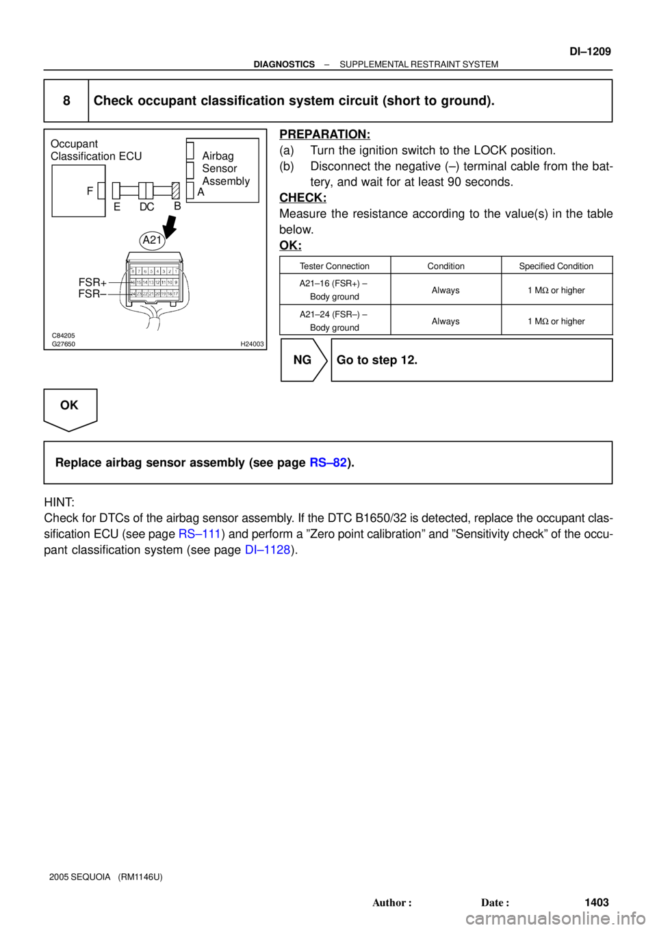
8 Check occupant classification system circuit (short to ground).
PREPARATION:
(a) Turn the ignition switch to the LOCK position.
(b) Disconnect the negative (±) terminal cable from the bat-
tery, and wait for at least 90 seconds.
CHECK:
Measure the resistance according to the value(s) in the table
below.
OK:
Tester ConnectionConditionSpecified Condition
A21±16 (FSR+) ±
Body groundAlways1 MW or higher
A21±24 (FSR±) ±
Body groundAlways1 MW or higher
NG Go to step 12.
OK
Replace airbag sensor assembly (see page RS±82).
HINT:
Check for DTCs of the airbag sensor assembly. If the DTC B1650/32 is detected, replace the occupant clas-
sification ECU (see page RS±111) and perform a ºZero point calibrationº and ºSensitivity checkº of the occu-
pant classification system (see page DI±1128).
Page 1412 of 4323

C84213
H43694H24024H24004
Occupant
Classification
ECUAirbag
Sensor
Assembly
A
O6
FSR+FSR±B C D E F
Service Wire
BL1
Seat Wire No. 1
Floor Wire
FSR+
FSR±
C84211H24024H24005
Occupant
Classification
ECU
Airbag
Sensor
Assembly
A
FSR+
FSR± B C D E F
BL1Seat Wire No. 1
Floor Wire
DI±1210
± DIAGNOSTICSSUPPLEMENTAL RESTRAINT SYSTEM
1404 Author�: Date�:
2005 SEQUOIA (RM1146U)
9 Check seat wire No. 1 (open).
PREPARATION:
Disconnect the seat wire No. 1 connector from the floor wire.
HINT:
The service wire has already been inserted into connector ºEº.
CHECK:
Measure the resistance according to the value(s) in the table
below.
OK:
Tester ConnectionConditionSpecified Condition
BL1±3 (FSR+) ±
BL1±5 (FSR±)AlwaysBelow 1 W
NG Repair or replace seat wire No. 1.
OK
Repair or replace floor wire.
10 Check seat wire No. 1 (short).
PREPARATION:
Disconnect the seat wire No. 1 connector from the floor wire.
CHECK:
Measure the resistance according to the value(s) in the table
below.
OK:
Tester ConnectionConditionSpecified Condition
BL1±3 (FSR+) ±
BL1±5 (FSR±)Always1 MW or higher
NG Repair or replace seat wire No. 1.
OK
Repair or replace floor wire.
Page 1413 of 4323
C84211H24024H24005
Occupant
Classification
ECU
Airbag
Sensor
Assembly
A
FSR+
FSR± B C D E F
BL1Seat Wire No. 1
Floor Wire
± DIAGNOSTICSSUPPLEMENTAL RESTRAINT SYSTEM
DI±1211
1405 Author�: Date�:
2005 SEQUOIA (RM1146U)
11 Check seat wire No. 1 (short to B+).
PREPARATION:
(a) Turn the ignition switch to the LOCK position.
(b) Disconnect the negative (±) terminal cable from the bat-
tery, and wait for at least for 90 seconds.
(c) Disconnect the seat wire No. 1 connector from the floor
wire.
(d) Connect the negative (±) terminal cable to the battery,
and wait for at least 2 seconds.
CHECK:
(a) Turn the ignition switch to the ON position.
(b) Measure the voltage according to the value(s) in the table
below.
OK:
Tester ConnectionConditionSpecified Condition
BL1±3 (FSR+) ±
Body groundIgnition switch ONBelow 1 V
BL1±5 (FSR±) ±
Body groundIgnition switch ONBelow 1 V
NG Repair or replace seat wire No. 1.
OK
Repair or replace floor wire.