Page 570 of 4323

DI±368
± DIAGNOSTICSENGINE
562 Author�: Date�:
2005 SEQUOIA (RM1146U)
TYPICAL MALFUNCTION THRESHOLDS
Detection CriteriaThreshold
Difference between ºtarget throttle positionº and ºactual
throttle positionº0.3 V or more
COMPONENT OPERATING RANGE
Standard Value
Commanded throttle position and current throttle position are nearly the same
WIRING DIAGRAM
Refer to DTC P2102 and P2103 on page DI±354.
INSPECTION PROCEDURE
HINT:
Read freeze frame data using the hand-held tester. Freeze frame data records the engine conditions when
a malfunction is detected. When troubleshooting, freeze frame data can help determine if the vehicle was
running or stopped, if the engine was warmed up or not, if the air±fuel ratio was lean or rich, as well as other
data from the time when a malfunction occurred.
1 Are there any other codes (besides DTC P2119) being output?
PREPARATION:
(a) Connect the hand±held tester to the DLC3.
(b) Turn the ignition switch ON and push the hand±held tester main switch ON.
(c) When using hand±held tester, enter the following menu: DIAGNOSIS / ENHANCED OBD II / DTC
INFO / CURRENT CODES.
CHECK:
Read the DTC using the hand±held tester.
RESULT:
Display (DTC Output)Proceed to
P2119A
ºP2119º and other DTCB
HINT:
If any other codes besides P2119 are output, perform the troubleshooting for those DTCs first.
B Go to relevant DTC chart (See page DI±58).
A
Page 577 of 4323
A19759
A37
Accelerator Pedal Position Sensor
VPA1
EP1
VCP1G±W
L±YECM
E4
2119
VPA2
EP2
VCP26
5
4
3
2
1G±R
G±B
L±B
L±RE4
E4
E4
E4
E426
27 18
20
VCP2 EPA2 VPA2 VCPAEPAVPA
± DIAGNOSTICSENGINE
DI±375
569 Author�: Date�:
2005 SEQUOIA (RM1146U)
WIRING DIAGRAM
Page 583 of 4323

FI7052DepressedReleased
± DIAGNOSTICSENGINE
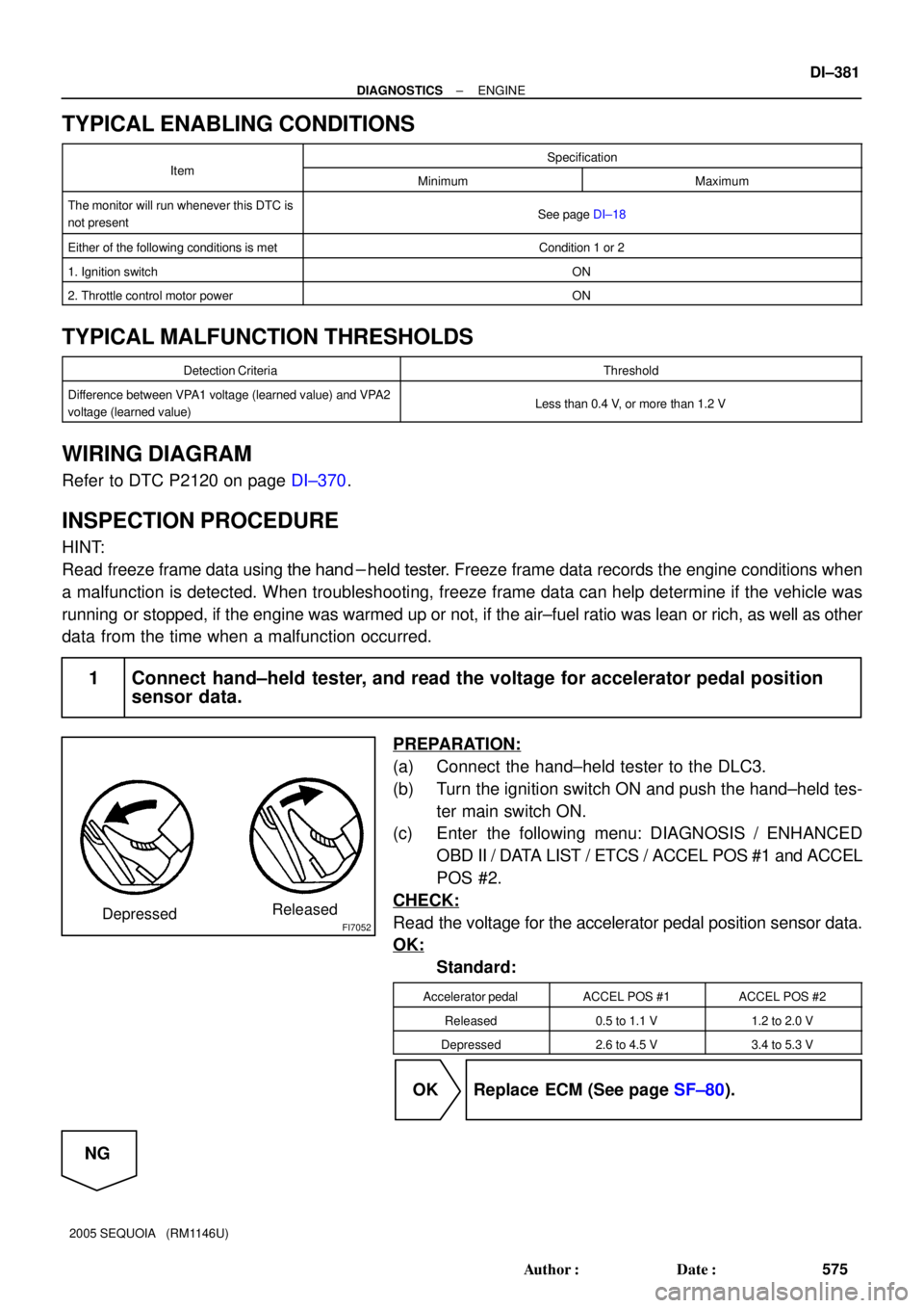
DI±381
575 Author�: Date�:
2005 SEQUOIA (RM1146U)
TYPICAL ENABLING CONDITIONS
ItSpecificationItemMinimumMaximum
The monitor will run whenever this DTC is
not presentSee page DI±18
Either of the following conditions is metCondition 1 or 2
1. Ignition switchON
2. Throttle control motor powerON
TYPICAL MALFUNCTION THRESHOLDS
Detection CriteriaThreshold
Difference between VPA1 voltage (learned value) and VPA2
voltage (learned value)Less than 0.4 V, or more than 1.2 V
WIRING DIAGRAM
Refer to DTC P2120 on page DI±370.
INSPECTION PROCEDURE
HINT:
Read freeze frame data using the hand-held tester. Freeze frame data records the engine conditions when
a malfunction is detected. When troubleshooting, freeze frame data can help determine if the vehicle was
running or stopped, if the engine was warmed up or not, if the air±fuel ratio was lean or rich, as well as other
data from the time when a malfunction occurred.
1 Connect hand±held tester, and read the voltage for accelerator pedal position
sensor data.
PREPARATION:
(a) Connect the hand±held tester to the DLC3.
(b) Turn the ignition switch ON and push the hand±held tes-
ter main switch ON.
(c) Enter the following menu: DIAGNOSIS / ENHANCED
OBD II / DATA LIST / ETCS / ACCEL POS #1 and ACCEL
POS #2.
CHECK:
Read the voltage for the accelerator pedal position sensor data.
OK:
Standard:
Accelerator pedalACCEL POS #1ACCEL POS #2
Released0.5 to 1.1 V1.2 to 2.0 V
Depressed2.6 to 4.5 V3.4 to 5.3 V
OK Replace ECM (See page SF±80).
NG
Page 591 of 4323
A23547
2
A1A± MREL
HA2A
A1A+ECM
22
30 B±W
E4
E7
E7 E7
BR W±B
2EFI Relay
A39 A/F Sensor
(Bank 2 Sensor 1)
J42
J/C Engine Room R/B No. 2
W 114
F10
FL
Block
Battery
ED(Shielded)8
EB 3
2HT
AF+ +B
B
E77
E04 2IA4
5
L±R G±R
2
G±B
2
B 1
B1
4
BRB±W
W±B 2F
A/F 1
1 12 Engine Room R/B and J/B
2D
2A2H
26
EFI No. 1 EFI No. 2
22
W±BA/F Relay
1 2
3
5A
AJ2
J/C
G±R
15
IA51
IG4
(Shielded)
G
R
ECE
ECCC
J42
J/C J5
J/CJ2
J/C B
B 5Engine
Room
R/B No. 2R±W
R±W
R±W
R±W
A38 A/F Sensor
(Bank 1 Sensor 1)
+B AF±
HT
AF+
AF±1
3 2
4
1
3 2
4 R±WL31
E7 23
E7 E7
A2A+
A2A±
HA1A B
R/B
± DIAGNOSTICSENGINE
DI±389
583 Author�: Date�:
2005 SEQUOIA (RM1146U)
WIRING DIAGRAM
Page 607 of 4323

± DIAGNOSTICSENGINE
DI±405
599 Author�: Date�:
2005 SEQUOIA (RM1146U) Time after A/F sensor heating
20 sec.±
Battery voltage10.5 V±
Ignition switchON
Others:
Battery voltage10.5 V±
Ignition switchON
TYPICAL MALFUNCTION THRESHOLDS
Detection CriteriaThreshold
P2238, P2241 (A/F sensor open circuit between AF+ and AF±):
A/F sensor admittanceBellow 0.022 1/ohm
P2238, P2241 (A/F sensor short circuit between AF+ and GND):
A/F+ terminal voltage0.5 V or less
P2238, P2241 (A/F sensor short circuit between AF+ and AF±):
Difference between A/F+ terminal and AF± terminal voltage0.1 V or less
P2239, P2242 (A/F sensor short circuit between AF+ and +B):
A/F+ terminal voltageMore than 4.5 V
P2252, P2255 (A/F sensor short circuit between AF± and GND):
A/F± terminal voltage0.5 V or less
P2253, P225+ (A/F sensor short circuit between AF± and +B):
A/F± terminal voltageMore than 4.5 V
WIRING DIAGRAM
Refer to DTC P2195 on page DI±383.
INSPECTION PROCEDURE
HINT:
Hand±held tester only:
Malfunctioning areas can be identified by performing the A/F CONTROL function provided in the ACTIVE
TEST. The A/F CONTROL function can help to determine whether the Air±Fuel Ratio (A/F) sensor, Heated
Oxygen (HO2) sensor and other potential trouble areas are malfunctioning.
The following instructions describe how to conduct the A/F CONTROL operation using a hand±held tester.
(1) Connect a hand±held tester to the DLC3.
(2) Start the engine and turn the tester ON.
(3) Warm up the engine at an engine speed of 2,500 rpm for approximately 90 seconds.
(4) On the tester, select the following menu items: DIAGNOSIS / ENHANCED OBD II / ACTIVE
TEST / A/F CONTROL.
(5) Perform the A/F CONTROL operation with the engine in an idling condition (press the RIGHT
or LEFT button to change the fuel injection volume).
(6) Monitor the voltage outputs of the A/F and HO2 sensors (AFS B1S1 (AFS B2S1) and OS2 B1S2
(O2S B2S2)) displayed on the tester.
HINT:
�The A/F CONTROL operation lowers the fuel injection volume by 12.5 % or increases the injection
volume by 25 %.
�Each sensor reacts in accordance with increases and decreases in the fuel injection volume.
Page 626 of 4323
A23557
ECM A42
Air Pressure Sensor
VC
AIP
E2
E8 E8 E8
2832 23
VC
AIP
E2EB4
EB4
EB4G±B G±B
B±Y
B±Y
G±W
G±W6 5 15 V
B17412
E8
E2AIP VC
B17439
Wire Harness Side:
Pressure Sensor Connector
A42
E2
AIP VC
DI±424
± DIAGNOSTICSENGINE
618 Author�: Date�:
2005 SEQUOIA (RM1146U)
WIRING DIAGRAM
INSPECTION PROCEDURE
1 Check for open and short in harness and connector between pressure sensor
and ECM (See page IN±35).
PREPARATION:
(a) Remove the intake manifold (see page EM±36).
(b) Disconnect the A42 pressure sensor connector.
(c) Disconnect the E8 ECM connector.
CHECK:
Measure the resistance between the wire harness side connec-
tors.
OK:
Standard:
Tester ConnectionSpecified Condition
VC (A42±1) ± VC (E8±23)
AIP (A42±2) ± AIP (E8±32)
E2 (A42±3) ± AIP (E8±28)
Below 1 W
VC (A42±1) or VC (E8±23) ±
Body ground
AIP (A42±2) or AIP (E8±32) ±
Body ground
10 kW or higher
NG Repair or replace harness and connector.
OK
Page 631 of 4323

± DIAGNOSTICSENGINE
DI±429
623 Author�: Date�:
2005 SEQUOIA (RM1146U)
MONITOR RESULT
Refer to page DI±26 for detailed information.
The test value and test limit information are described as shown in the following table. Check the monitor
result and test values after performing the monitor drive pattern (refer to ºConfirmation Monitorº).
�MID (Monitor Identification Data) is assigned to each emissions±related component.
�TID (Test Identification Data) is assigned to each test value.
�Scaling is used to calculate the test value indicated on generic OBD ll scan tools.
Secondary air injection (AIR) system
MIDTIDScalingDescription of Test ValueMinimum Test LimitMaximum Test Limit
$71$E1Multiply by 0.01
(g/s)Test value of AIR amount insufficientMinimum test limitMaximum test limit
$71$E2Multiply by 0.01
(kPa)Test value of AIR pump stuck ONMinimum test limitMaximum test limit
$71$E3Multiply by 0.01
(kPa)Test value of AIR pump stuck OFFMinimum test limitMaximum test limit
$71$E4Multiply by 0.01
(kPa)Test value of AIR control valve ONMinimum test limitMaximum test limit
$71$E5Multiply by 0.01
(kPa)Test value of AIR control valve OFFMinimum test limitMaximum test limit
$71$E6Multiply by 0.01
(kPa)Test value of AIR pressure change for
AIR valveMinimum test limitMaximum test limit
$71$E7Multiply by 0.01
(kPa)Test value of AIR pressure change for
AIR VSV bank 1Minimum test limitMaximum test limit
$71$E8Multiply by 0.01
(kPa)Test value of AIR pressure change for
AIR VSV bank 2Minimum test limitMaximum test limit
$71$E9Multiply by 0.01
(kPa)Test value of AIR pressure pulsation for
AIR VSV when AIR pressure is lowMinimum test limitMaximum test limit
WIRING DIAGRAM
Refer to DTC P0412 on page DI±234.
Page 655 of 4323

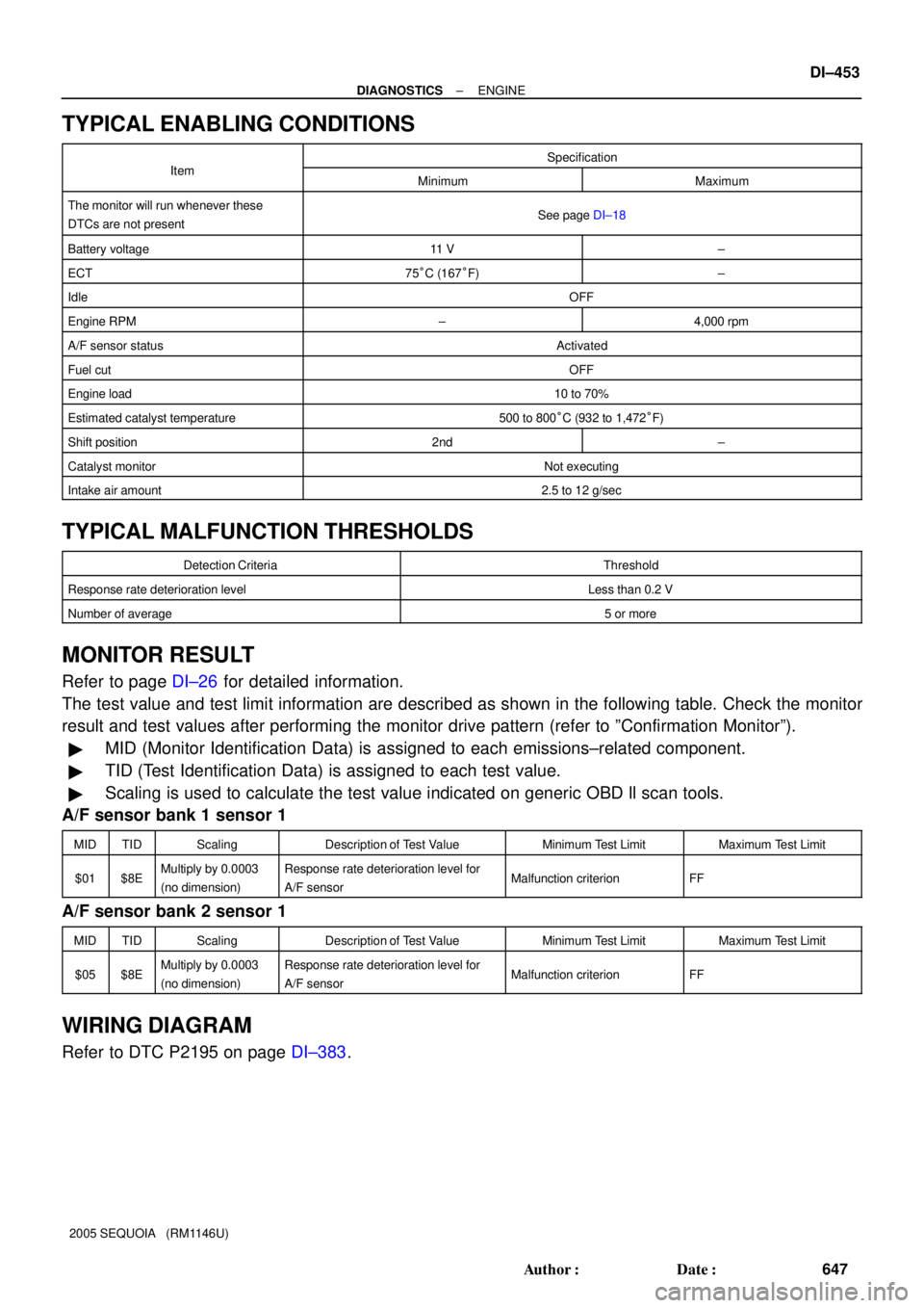
± DIAGNOSTICSENGINE
DI±453
647 Author�: Date�:
2005 SEQUOIA (RM1146U)
TYPICAL ENABLING CONDITIONS
ItSpecificationItemMinimumMaximum
The monitor will run whenever these
DTCs are not presentSee page DI±18
Battery voltage11 V±
ECT75°C (167°F)±
IdleOFF
Engine RPM±4,000 rpm
A/F sensor statusActivated
Fuel cutOFF
Engine load10 to 70%
Estimated catalyst temperature500 to 800°C (932 to 1,472°F)
Shift position2nd±
Catalyst monitorNot executing
Intake air amount2.5 to 12 g/sec
TYPICAL MALFUNCTION THRESHOLDS
Detection CriteriaThreshold
Response rate deterioration levelLess than 0.2 V
Number of average5 or more
MONITOR RESULT
Refer to page DI±26 for detailed information.
The test value and test limit information are described as shown in the following table. Check the monitor
result and test values after performing the monitor drive pattern (refer to ºConfirmation Monitorº).
�MID (Monitor Identification Data) is assigned to each emissions±related component.
�TID (Test Identification Data) is assigned to each test value.
�Scaling is used to calculate the test value indicated on generic OBD ll scan tools.
A/F sensor bank 1 sensor 1
MIDTIDScalingDescription of Test ValueMinimum Test LimitMaximum Test Limit
$01$8EMultiply by 0.0003
(no dimension)Response rate deterioration level for
A/F sensorMalfunction criterionFF
A/F sensor bank 2 sensor 1
MIDTIDScalingDescription of Test ValueMinimum Test LimitMaximum Test Limit
$05$8EMultiply by 0.0003
(no dimension)Response rate deterioration level for
A/F sensorMalfunction criterionFF
WIRING DIAGRAM
Refer to DTC P2195 on page DI±383.