Page 2341 of 4323
9
10")
I28592
Multi±display
Controller Sub±assy R25
Television Display Assy
IF49
LG5
TX2+ ID217
R21
LG LG
IF410
LG4
TX2± ID218
R21
LG LG TX+
TX±
LG31
TX+
IF314
R23
L
LG30
TX± IF315
R23
LG TX+ (*1)9
10
9
10 � R27 (*1)
Radio and Navigation Assy
� R19 (*2)
Radio Receiver Assy
D23
Disc Player Controller
13
TX3± R22
LG
14
TX3+ R22 TX±
TX+18
17
LG
*1: w/ Navigation System
*2: w/o Navigation SystemTX1+ (*2)
TX± (*1)
TX1± (*2)
± DIAGNOSTICSREAR SEAT ENTERTAINMANT SYSTEM
DI±2139
2333 Author�: Date�:
2005 SEQUOIA (RM1146U)
AVC±LAN circuit
CIRCUIT DESCRIPTION
Each unit of this system connected to the AVC±LAN (communication bus) transfers the signal of each switch
by communication.
When a short to +B or short to ground occurs in this AVC± LAN, this system will not function normally as
communication is discontinued.
This system has 2 kinds of AVC±LAN: main AVC±LAN and sub AVC±LAN.
w/ navigation system:
In the main AVC±LAN, the radio and navigation assy becomes the communication master and has enough
resistance necessary for communication.
w/o navigation system:
In the main AVC±LAN, the radio receiver assy becomes the communication master and has enough resis-
tance necessary for communication.
In the sub AVC±LAN, the multi±display controller sub±assy becomes the communication master and has
enough resistance necessary for communication.
WIRING DIAGRAM
DIDBJ±01
Page 2342 of 4323
DI±2140
± DIAGNOSTICSREAR SEAT ENTERTAINMANT SYSTEM
2334 Author�: Date�:
2005 SEQUOIA (RM1146U)
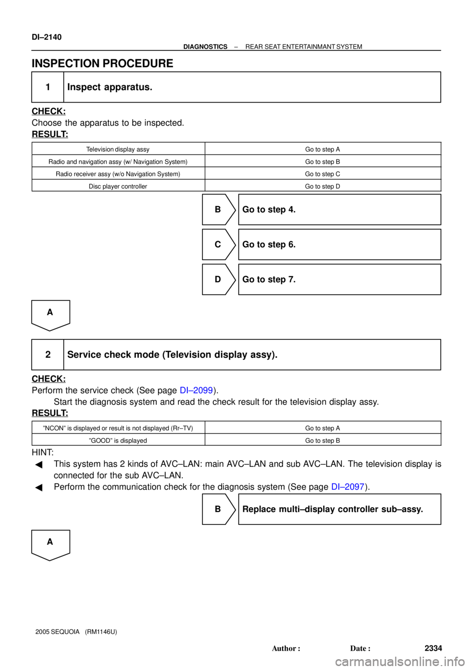
INSPECTION PROCEDURE
1 Inspect apparatus.
CHECK:
Choose the apparatus to be inspected.
RESULT:
Television display assyGo to step A
Radio and navigation assy (w/ Navigation System)Go to step B
Radio receiver assy (w/o Navigation System)Go to step C
Disc player controllerGo to step D
B Go to step 4.
C Go to step 6.
D Go to step 7.
A
2 Service check mode (Television display assy).
CHECK:
Perform the service check (See page DI±2099).
Start the diagnosis system and read the check result for the television display assy.
RESULT:
ºNCONº is displayed or result is not displayed (Rr±TV)Go to step A
ºGOODº is displayedGo to step B
HINT:
�This system has 2 kinds of AVC±LAN: main AVC±LAN and sub AVC±LAN. The television display is
connected for the sub AVC±LAN.
�Perform the communication check for the diagnosis system (See page DI±2097).
B Replace multi±display controller sub±assy.
A
Page 2344 of 4323
DI±2142
± DIAGNOSTICSREAR SEAT ENTERTAINMANT SYSTEM
2336 Author�: Date�:
2005 SEQUOIA (RM1146U)
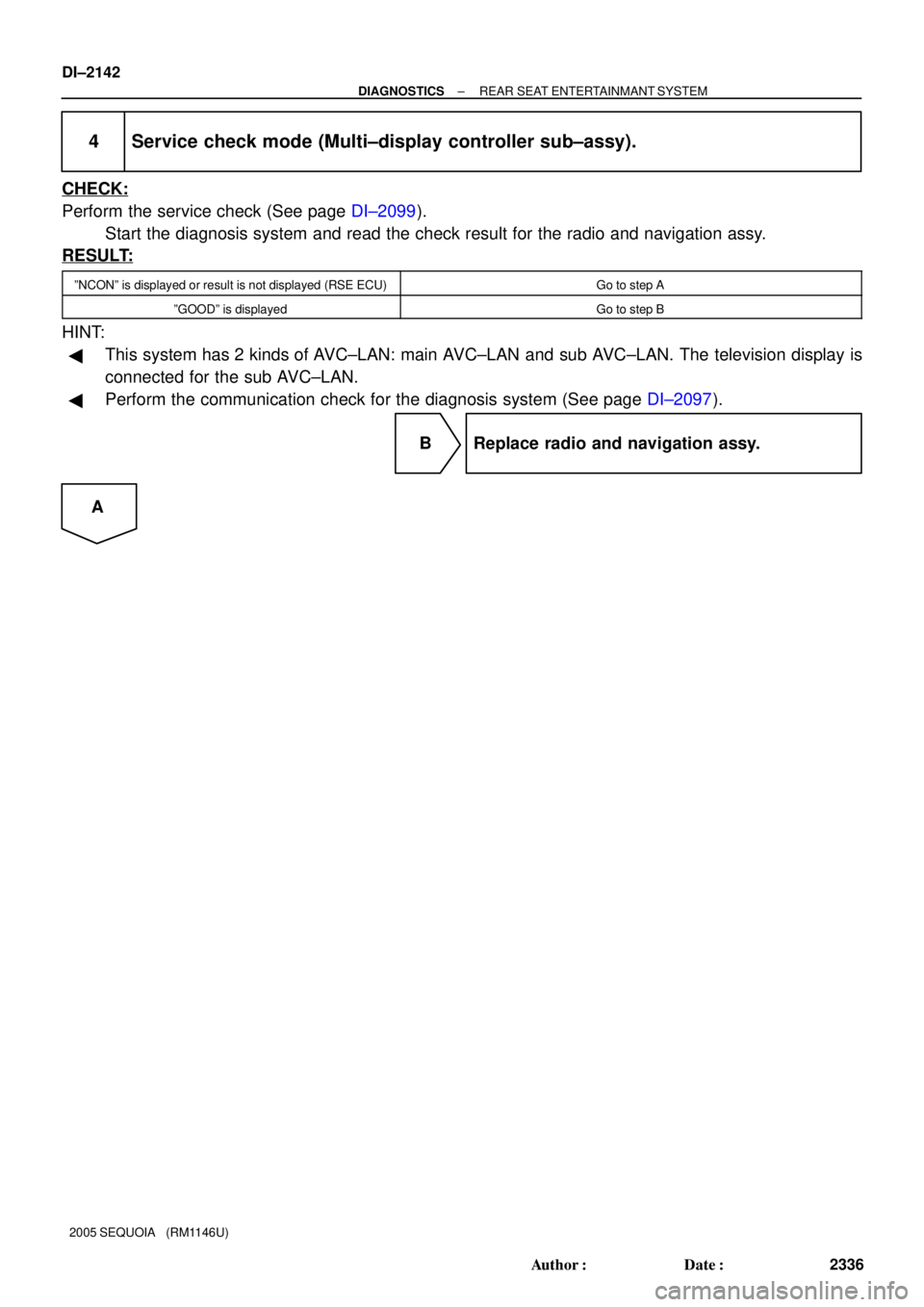
4 Service check mode (Multi±display controller sub±assy).
CHECK:
Perform the service check (See page DI±2099).
Start the diagnosis system and read the check result for the radio and navigation assy.
RESULT:
ºNCONº is displayed or result is not displayed (RSE ECU)Go to step A
ºGOODº is displayedGo to step B
HINT:
�This system has 2 kinds of AVC±LAN: main AVC±LAN and sub AVC±LAN. The television display is
connected for the sub AVC±LAN.
�Perform the communication check for the diagnosis system (See page DI±2097).
B Replace radio and navigation assy.
A
Page 2345 of 4323

I28750
Radio and Navigation Assy:
TX±TX+
R27
I28614
TX+ Multi±display Controller Sub±assy:
R23TX±
± DIAGNOSTICSREAR SEAT ENTERTAINMANT SYSTEM
DI±2143
2337 Author�: Date�:
2005 SEQUOIA (RM1146U)
5 Check harness and connector (Radio and navigation assy ± multi±display con-
troller sub±assy).
PREPARATION:
Disconnect the R23 and R27 connectors.
CHECK:
Measure the resistance according to the value(s) in the table
below.
OK:
Symbol (Tester connection)ConditionSpecified condition
TX+ (R27±9) ± TX+ (R23±31)AlwaysBelow 1 W
TX± (R27±10) ± TX± (R23±30)AlwaysBelow 1 W
TX+ (R27±9) ± Body groundAlways10 kW or higher
TX± (R27±10) ± Body groundAlways10 kW or higher
NG Repair or replace harness or connector.
OK
Replace multi±display controller sub±assy.
6 Service check mode (Multi±display controller sub±assy).
CHECK:
Perform the service check (See page DI±2099).
Start the diagnosis system and read the check result for the radio and navigation assy.
RESULT:
ºNCONº is displayed or result is not displayed (RSE ECU)Go to step A
ºGOODº is displayedGo to step B
HINT:
�This system has 2 kinds of AVC±LAN: main AVC±LAN and sub AVC±LAN. The television display is
connected for the sub AVC±LAN.
�Perform the communication check for the diagnosis system (See page DI±2097).
B Replace radio receiver assy.
A
Page 2349 of 4323
I28598
Multi±display
Controller Sub±assy
LG28
RMUT
IF316
R23
R±W
LG12
LMUT IF34
R23
R±G RMU
MUTE Radio Receiver Assy
19
R19
6
R20 w/o Navigation System:
I28598
Multi±display
Controller Sub±assy
LG28
RMUT
IF316
R23
R±W
LG12
LMUT IF34
R23
R±G RMUT
MUTE Radio and Navigation Assy
19
R27
6
R28 w/ Navigation System:
± DIAGNOSTICSREAR SEAT ENTERTAINMANT SYSTEM
DI±2147
2341 Author�: Date�:
2005 SEQUOIA (RM1146U)
Mute signal circuit (Radio receiver assy / Radio and navigation
assy ± Multi±display controller sub±assy)
CIRCUIT DESCRIPTION
The multi±display controller sub±assy controls the volume according to the MUTE signal from the radio re-
ceiver assy or radio and navigation assy.
The MUTE signal is sent to reduce noise and a popping sound generated when the mode, etc. is switched.
WIRING DIAGRAM
DIDBK±01
Page 2350 of 4323
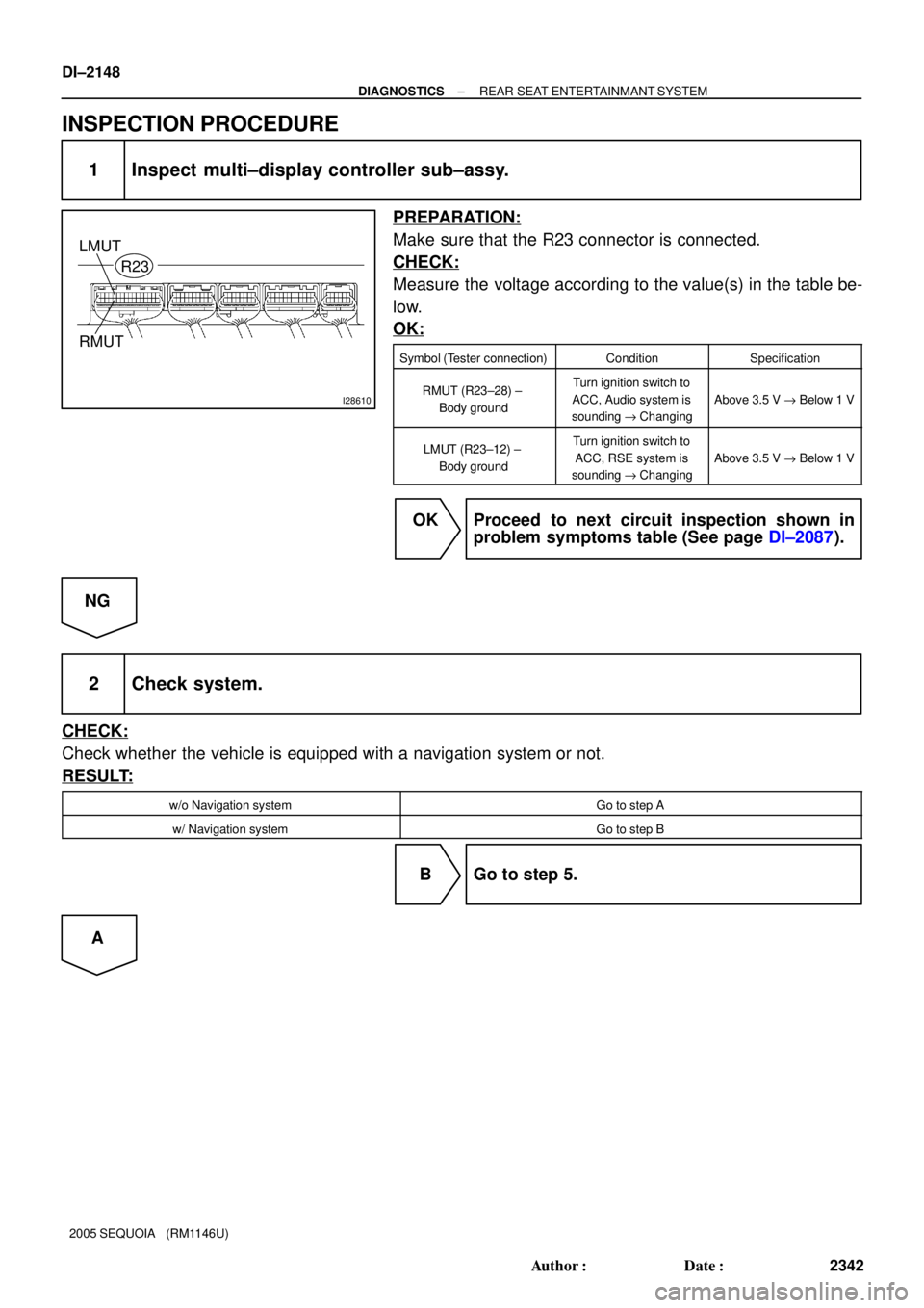
I28610
RMUT
R23
LMUT
DI±2148
± DIAGNOSTICSREAR SEAT ENTERTAINMANT SYSTEM
2342 Author�: Date�:
2005 SEQUOIA (RM1146U)
INSPECTION PROCEDURE
1 Inspect multi±display controller sub±assy.
PREPARATION:
Make sure that the R23 connector is connected.
CHECK:
Measure the voltage according to the value(s) in the table be-
low.
OK:
Symbol (Tester connection)ConditionSpecification
RMUT (R23±28) ±
Body groundTurn ignition switch to
ACC, Audio system is
sounding "Changing
Above 3.5 V " Below 1 V
LMUT (R23±12) ±
Body groundTurn ignition switch to
ACC, RSE system is
sounding "Changing
Above 3.5 V " Below 1 V
OK Proceed to next circuit inspection shown in
problem symptoms table (See page DI±2087).
NG
2 Check system.
CHECK:
Check whether the vehicle is equipped with a navigation system or not.
RESULT:
w/o Navigation systemGo to step A
w/ Navigation systemGo to step B
B Go to step 5.
A
Page 2353 of 4323
I28299RMUT
Radio and Navigation Assy
Wire Harness View:
R27
I28612MUTE
Radio and Navigation Assy
Wire Harness View:
R28
I29009
Multi±display Controller Sub±assy:
RMUT
R23
LMUT
± DIAGNOSTICSREAR SEAT ENTERTAINMANT SYSTEM
DI±2151
2345 Author�: Date�:
2005 SEQUOIA (RM1146U)
5 Check harness and connector (Radio and navigation assy ± Multi±display con-
troller sub±assy).
PREPARATION:
Disconnect the R23, R27 and R28 connectors.
CHECK:
Measure the resistance according to the value(s) in the table
below.
OK:
Symbol (Tester connection)ConditionSpecified condition
RMUT (R23±28) ± RMUT (R27±19)AlwaysBelow 1 W
LMUT (R23±12) ± MUTE (R28±6)AlwaysBelow 1 W
RMUT (R23±28) ± Body groundAlways10 kW or higher
LMUT (R23±12) ± Body groundAlways10 kW or higher
NG Repair or replace harness or connector.
OK
Page 2354 of 4323
DI±2152
± DIAGNOSTICSREAR SEAT ENTERTAINMANT SYSTEM
2346 Author�: Date�:
2005 SEQUOIA (RM1146U)
6 Replace multi±display controller sub±assy.
CHECK:
Replace the multi±display controller sub±assy and check if it operates normally.
OK:
Normal operation.
OK Normal operation.
NG
Replace radio and navigation assy.