Page 2299 of 4323
DIDB1±01
I28273
RSE system normal operation
Diagnosis start±up (w/ Navigation system: See page DI±2191)
Select ºMENUº and enter
ºDiagnosis MENUº using a
remote controller.
ºService Check Modeº
screen to section
(See page DI±2099) ºDisplay Checkº
screen to section
(See page DI±2085)Start±up of the diagnostics function for the ºaudio system
and TOYOTA navigation systemº is linked with the start±
up of the diagnostics function of the ºrear displayº.
(w/o Navigation system: See page DI±1974)
Illustrations may differ from the actual vehicle depending on the device settings and options. There-
fore, some detailed areas may not be shown exactly the same as on the actual vehicle.
± DIAGNOSTICSREAR SEAT ENTERTAINMANT SYSTEM
DI±2097
2291 Author�: Date�:
2005 SEQUOIA (RM1146U)
DIAGNOSIS SYSTEM
DIAGNOSIS CHECK
HINT:
Diagnosis system mode is operated as follows.
Page 2305 of 4323

DIAGNOSTIC TROUBLE CODE CHART
TermsMeaning
Physical addressThree±digit code (shown in hex")
DIDB3±01
± DIAGNOSTICSREAR SEAT ENTERTAINMANT SYSTEM
DI±2103
2297 Author�: Date�:
2005 SEQUOIA (RM1146U)
DIAGNOSTIC TROUBLE CODE CHART
TermsMeaning
Physical addressThree±digit code (shown in hexadecimal) which is given to each component com-
prising the AVC±LAN.
Corresponding to the function, individual symbols are specified.
Logical addressTwo±digit code (shown in hexadecimal) which is given to each function comprising
the inner system of the AVC±LAN.
HINT:
DTC of the device which is directly connected via AVC±LAN, is displayed on the ºaudio system or navigation
systemº and the ºtelevision display assyº respectively.
Titles for each unit are stated in the following order: parts name (physical address) [Name indicated by DTC]
1. MULTI±DISPLAY CONTROLLER SUB±ASSY (Physical address: 16C, 16D) [RSE±ECU]
HINT:
�*1: Even if no failure is detected, this code may be stored depending on the battery condition or voltage
for starting the engine.
�*2: This code is stored 180 seconds after the power supply connector is disconnected after engine
start.
�*3: This code may be stored when the engine key is turned back to the ON position and then turned
again to the START position after engine start.
�*4: This code may be stored when the engine key is turned back to the ON position and then turned
again to the START position in 1 minute after engine start.
(a) Logical address: 01 (Communication control)
DTCNameDiagnosisVerificationSee page
D8
*2No Response To Connection
CheckComponent shown by sub±code is or had been
disconnected from system after engine start.
1. Power source circuit (Television
display assy).
2. Power source circuit (Disc play-
er controller).
3. AVC±LAN circuit.
4. Replace television display assy.
5. Replace disc player controller.DI±2107
DI±2112
DI±2139
±
±
D9
*1Last Mode Error
Component operated (sound and/or image was
provided) before engine stop is or was discon-
nected with ignition switch in the ACC or ON posi-
tion.
1. Power source circuit (Television
display assy).
2. Power source circuit (Disc play-
er controller).
3. AVC±LAN circuit
4. Replace television display assy.
5. Replace disc player controller.DI±2107
DI±2112
DI±2139
±
±
DANo Response to ON/OFF
Instruction
No response is identified when changing mode
(audio and visual mode change).
Detected when sound and picture do not change
by button operation.
1. Power source circuit (Television
display assy).
2. Power source circuit (Disc play-
er controller).
3. AVC±LAN circuit
4. Replace television display assy.
5. Replace disc player controller.DI±2107
DI±2112
DI±2139
±
±
DB
*1Mode Status ErrorDual alarm is detected.
1. Power source circuit (Television
display assy).
2. Power source circuit (Disc play-
er controller).
3. AVC±LAN circuit
4. Replace television display assy.
5. Replace disc player controller.DI±2107
DI±2112
DI±2139
±
±
Page 2321 of 4323
I28667
Multi±display
Controller Sub±assy
NTS1
SGN1
SG3 R2321
R2320
R2319 R
G
(Shielded) Radio and Navigation Assy
BR
BR
(Shielded) R261
R264
R265 NTSC
SGD1
SGNDIF322
IF323
IF324
± DIAGNOSTICSREAR SEAT ENTERTAINMANT SYSTEM
DI±2119
2313 Author�: Date�:
2005 SEQUOIA (RM1146U)
Display signal circuit (Multi±display sub±assy ± Radio and navi-
gation assy)
CIRCUIT DESCRIPTION
This is the display signal circuit from the multi±display controller sub±assy to the radio and navigation assy.
WIRING DIAGRAM
DIDB9±01
Page 2322 of 4323
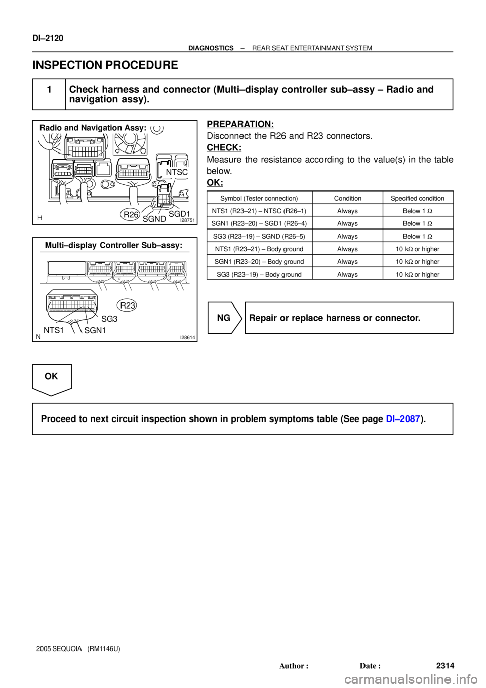
I28751
NTSC
R26
Radio and Navigation Assy:
SGNDSGD1
I28614NTS1R23
Multi±display Controller Sub±assy:
SGN1SG3
DI±2120
± DIAGNOSTICSREAR SEAT ENTERTAINMANT SYSTEM
2314 Author�: Date�:
2005 SEQUOIA (RM1146U)
INSPECTION PROCEDURE
1 Check harness and connector (Multi±display controller sub±assy ± Radio and
navigation assy).
PREPARATION:
Disconnect the R26 and R23 connectors.
CHECK:
Measure the resistance according to the value(s) in the table
below.
OK:
Symbol (Tester connection)ConditionSpecified condition
NTS1 (R23±21) ± NTSC (R26±1)AlwaysBelow 1 W
SGN1 (R23±20) ± SGD1 (R26±4)AlwaysBelow 1 W
SG3 (R23±19) ± SGND (R26±5)AlwaysBelow 1 W
NTS1 (R23±21) ± Body groundAlways10 kW or higher
SGN1 (R23±20) ± Body groundAlways10 kW or higher
SG3 (R23±19) ± Body groundAlways10 kW or higher
NG Repair or replace harness or connector.
OK
Proceed to next circuit inspection shown in problem symptoms table (See page DI±2087).
Page 2327 of 4323
I28597
IF3
L+ R±
R+
L± 6
W
(Shielded)Multi±display
Controller Sub±assy
R2310
R239
R238
R237
R2311 W
W
W IF37
IF38
IF39
IF35
(Shielded) W
G
B
R CDL+ CDR± CDR+
CDL±R282
R283
R284
R285
R281
CSLDSG1 Radio and Navigation Assy
± DIAGNOSTICSREAR SEAT ENTERTAINMANT SYSTEM
DI±2125
2319 Author�: Date�:
2005 SEQUOIA (RM1146U)
Sound signal circuit (From multi±display controller sub±assy to
radio and navigation assy)
CIRCUIT DESCRIPTION
This is the sound signal circuit from the multi±display controller sub±assy to the radio and navigation assy.
WIRING DIAGRAM
DIDBC±01
Page 2328 of 4323

I28612
Radio and Navigation Assy
Wire Harness View:
R28
CDL+CDR±
CSLDCDL±
CDR+
I28614
R23
L+ SG1
R±L±
R+
Multi±display Controller Sub±assy:
DI±2126
± DIAGNOSTICSREAR SEAT ENTERTAINMANT SYSTEM
2320 Author�: Date�:
2005 SEQUOIA (RM1146U)
INSPECTION PROCEDURE
1 Check harness and connector (Radio and navigation assy ± Multi±display con-
troller sub±assy).
PREPARATION:
Disconnect the R23 and R28 connectors.
CHECK:
Measure the resistance according to the value(s) in the table
below.
OK:
Symbol (Tester connection)ConditionSpecified condition
CDL+ (R28±4) ± L+ (R23±8)AlwaysBelow 1 W
CDL± (R28±5) ± L± (R23±7)AlwaysBelow 1 W
CDR+ (R28±2) ± R+ (R23±10)AlwaysBelow 1 W
CDR± (R28±3) ± R± (R23±9)AlwaysBelow 1 W
CSLD (R28±1) ± SG1 (R23±11)AlwaysBelow 1 W
CDL+ (R28±4) ± Body groundAlways10 kW or higher
CDL± (R28±5) ± Body groundAlways10 kW or higher
CDR+ (R28±2) ± Body groundAlways10 kW or higher
CDR± (R28±3) ± Body groundAlways10 kW or higher
CSLD (R28±1) ± Body groundAlways10 kW or higher
NG Repair or replace harness or connector.
OK
Proceed to next circuit inspection shown in problem symptoms table (See page DI±2087).
Page 2331 of 4323
I28597
IF3
R±L+ R±R±
R±R+
R±L± W
(Shielded)Multi±display
Controller Sub±assy
R2326
R2325
R2324
R2323
R2327 W
W
W IF3
IF3
IF3
IF3
(Shielded) R±L+ R±R±
R±R+
R±L±R2715
R2716
R2717
R2718
R2714
RSLD
SG2 Radio and Navigation Assy
W
G
B
R18
19
20
21
17
± DIAGNOSTICSREAR SEAT ENTERTAINMANT SYSTEM
DI±2129
2323 Author�: Date�:
2005 SEQUOIA (RM1146U)
Sound signal circuit (From radio and navigation assy to multi±
display sub±assy)
CIRCUIT DESCRIPTION
This is the sound signal circuit from the radio and navigation assy to the multi±display controller sub±assy.
WIRING DIAGRAM
DIDBE±01
Page 2332 of 4323

I28750
Radio and Navigation Assy:
R27
RSLD
R±R+
R±R± R±L+ R±L±
I28614
SG2R23
Multi±display Controller Sub±assy:
R±R+
R±R±R±L+R±L±
DI±2130
± DIAGNOSTICSREAR SEAT ENTERTAINMANT SYSTEM
2324 Author�: Date�:
2005 SEQUOIA (RM1146U)
INSPECTION PROCEDURE
1 Check harness and connector (Radio and navigation assy ± Multi±display con-
troller sub±assy).
PREPARATION:
Disconnect the R23 and R27 connectors.
CHECK:
Measure the resistance according to the value(s) in the table
below.
OK:
Symbol (Tester connection)ConditionSpecified condition
R±R+ (R27±15) ± R±R+ (R23±26)AlwaysBelow 1 W
R±R± (R27±16) ± R±R± (R23±25)AlwaysBelow 1 W
R±L+ (R27±17) ± R±L+ (R23±24)AlwaysBelow 1 W
R±L± (R27±18) ± R±L± (R23±23)AlwaysBelow 1 W
RSLD (R27±14) ± SG2 (R23±27)AlwaysBelow 1 W
R±R+ (R27±15) ± Body groundAlways10 kW or higher
R±R± (R27±16) ± Body groundAlways10 kW or higher
R±L+ (R27±17) ± Body groundAlways10 kW or higher
R±L± (R27±18) ± Body groundAlways10 kW or higher
RSLD (R27±14) ± Body groundAlways10 kW or higher
NG Repair or replace harness or connector.
OK
Proceed to next circuit inspection shown in problem symptoms table (See page DI±2087).

Select ºMENUº and enter
ºDiagnosis MENUº using a
remote controller.
ºService Check Mode�")
 Radio and Navigation Assy
BR
BR
(Shielded) R261
R264
R265 NTSC
SGD1
SGNDIF322
IF323
IF324
± DIAGNOSTICSREAR")
Multi±display
Controller Sub±assy
R2310
R239
R238
R237
R2311 W
W
W IF37
IF38
IF39
IF35
(Shielded) W
G
B
R CDL+ CDR± CDR+
CDL±R282
R283
R284
R285
R281
CSLDSG")
Multi±display
Controller Sub±assy
R2326
R2325
R2324
R2323
R2327 W
W
W IF3
IF3
IF3
IF3
(Shielded) R±L+ R±R±
R±R+
R±L±R2715
R2716
R2717
R2718
R2")