Page 2542 of 4323

DI±2340
± DIAGNOSTICSAIR CONDITIONING SYSTEM
2534 Author�: Date�:
2005 SEQUOIA (RM1146U)
INSPECTION PROCEDURE
1 Ch")
I05252
21
N02774
0.2 V/Din.
LOCK IN signal waveform
0 V
20 msec/Division (Idling)
DI±2340
± DIAGNOSTICSAIR CONDITIONING SYSTEM
2534 Author�: Date�:
2005 SEQUOIA (RM1146U)
INSPECTION PROCEDURE
1 Check compressor.
PREPARATION:
(a) Check and adjust compressor drive belt tension (See page AC±15).
CHECK:
(a) Check that the compressor does not lock when starting the engine and turning the A/C switch on.
OK: Cooler compressor assy does not lock during operation
HINT:
If the compressor drive belt slips when the A/C switch is on, the magnet clutch seems to be locked.
If the condition continues for more than 3 seconds, the A/C amplifier turns off the magnet clutch for compres-
sor drive belt protection.
NG Replace compressor.
OK
2 Check compressor lock sensor.
PREPARATION:
Disconnect the compressor connector.
CHECK:
Measure the resistance between terminals 1 and 2 of the com-
pressor lock sensor connector.
OK:
Resistance : 65 to 125 W at 20°C (68 °F)
Reference: Inspection using oscilloscope
During cranking or idling, measure the voltage between termi-
nals LOCK and SG±TAM of the integration control and panel.
HINT:
The correct waveform appears as shown in the illustration on
the left.
NG Replace compressor.
OK
Page 2883 of 4323
ST08X±03
± STARTINGSTARTING SYSTEM
ST±1
2875 Author�: Date�:
2005 SEQUOIA (RM1146U)
STARTING SYSTEM
ON±VEHICLE INSPECTION
NOTICE:
Before changing the starter, check these items again:
�Connector connection
�Accessory installation, e.g.: engine immobilizer system
Page 2885 of 4323
B17496
Injector Connector
VSV Connector
for EVAP
Starter ConnectorStarterIntake Manifold Assembly Engine Wire and Clamp
� Gasket
� Non±reusable part
39 (400, 29)
Engine Wire
Protector
Fuel Return Hose
Engine Wire
N´m (kgf´cm, ft´lbf) : Specified torque� GasketFuel Inlet Hose
Air Switching Valve No.2
� Gasket
� Gasket
10 (102, 7 )
10 (102, 7 )
10 (102, 7 )
10 (102, 7 )
± STARTINGSTARTER
ST±3
2877 Author�: Date�:
2005 SEQUOIA (RM1146U)
Page 2887 of 4323
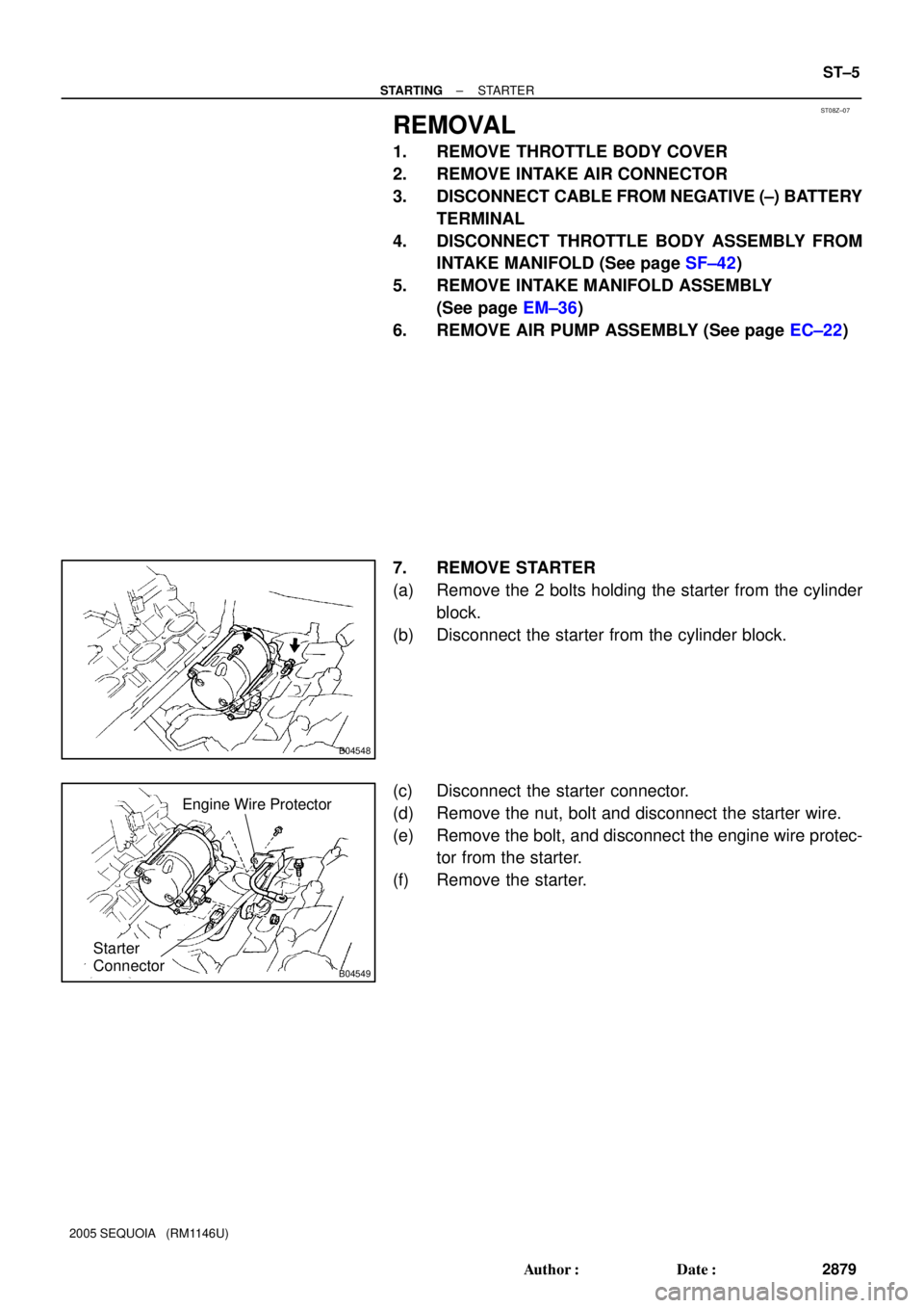
ST08Z±07
B04548
B04549
Starter
Connector
Engine Wire Protector
± STARTINGSTARTER
ST±5
2879 Author�: Date�:
2005 SEQUOIA (RM1146U)
REMOVAL
1. REMOVE THROTTLE BODY COVER
2. REMOVE INTAKE AIR CONNECTOR
3. DISCONNECT CABLE FROM NEGATIVE (±) BATTERY
TERMINAL
4. DISCONNECT THROTTLE BODY ASSEMBLY FROM
INTAKE MANIFOLD (See page SF±42)
5. REMOVE INTAKE MANIFOLD ASSEMBLY
(See page EM±36)
6. REMOVE AIR PUMP ASSEMBLY (See page EC±22)
7. REMOVE STARTER
(a) Remove the 2 bolts holding the starter from the cylinder
block.
(b) Disconnect the starter from the cylinder block.
(c) Disconnect the starter connector.
(d) Remove the nut, bolt and disconnect the starter wire.
(e) Remove the bolt, and disconnect the engine wire protec-
tor from the starter.
(f) Remove the starter.
Page 2898 of 4323
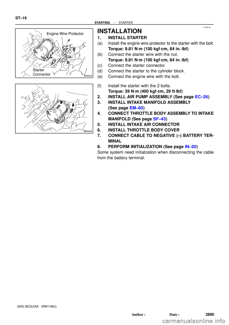
ST095±06
B04549
Starter
Connector
Engine Wire Protector
B04548
ST±16
± STARTINGSTARTER
2890 Author�: Date�:
2005 SEQUOIA (RM1146U)
INSTALLATION
1. INSTALL STARTER
(a) Install the engine wire protector to the starter with the bolt.
Torque: 9.81 N´m (100 kgf´cm, 84 in.´lbf)
(b) Connect the starter wire with the nut.
Torque: 9.81 N´m (100 kgf´cm, 84 in.´lbf)
(c) Connect the starter connector.
(d) Connect the starter to the cylinder block.
(e) Connect the engine wire with the bolt.
(f) Install the starter with the 2 bolts.
Torque: 39 N´m (400 kgf´cm, 29 ft´lbf)
2. INSTALL AIR PUMP ASSEMBLY (See page EC±26)
3. INSTALL INTAKE MANIFOLD ASSEMBLY
(See page EM±60)
4. CONNECT THROTTLE BODY ASSEMBLY TO INTAKE
MANIFOLD (See page SF±43)
5. INSTALL INTAKE AIR CONNECTOR
6. INSTALL THROTTLE BODY COVER
7. CONNECT CABLE TO NEGATIVE (±) BATTERY TER-
MINAL
8. PERFORM INITIALIZATION (See page IN±20)
Some system need initialzation when disconnecting the cable
from the battery terminal.
Page 3873 of 4323

14
2005 SEQUOIA from Aug. 04 Prod. (OM34424U)
Your vehicle is supplied with the two
kinds of keys.
1. Master keys (black)ÐThese keys work
in every lock. Your Toyota dealer wi")
05_SEQUOIA_U (L/O 0408)
14
2005 SEQUOIA from Aug. '04 Prod. (OM34424U)
Your vehicle is supplied with the two
kinds of keys.
1. Master keys (black)ÐThese keys work
in every lock. Your Toyota dealer will
need one of them to make a new key
with a built±in transponder chip.
2. Sub key (gray)ÐThis key will not work
in the glove box.
A transponder chip for engine immobilizer
system has been placed in the head of
the master and sub keys. These chips are
needed to enable the system to function
correctly, so be careful not to lose these
keys. If you make your own duplicate key,
you will not be able to cancel the system
or start the engine.To protect items locked in the glove box
when using valet parking, leave the sub
key with the attendant.
Since the side doors can be locked with-
out a key, you should always carry a
spare key in case you accidentally lock
your keys inside the vehicle.NOTICE
When using a key containing a trans-
ponder chip, observe the following
precautions:
�When starting the engine, do not
use the key with a key ring resting
on the key grip and do not press
the key ring against the key grip.
Otherwise the engine may not start,
or may stop soon after it starts.
Keys
Page 3874 of 4323
05_SEQUOIA_U (L/O 0408)
15
2005 SEQUOIA from Aug. '04 Prod. (OM34424U)
�When starting the engine, do not
use the key with other transponder
keys around (including keys of oth-
er vehicles) and do not press other
key plates against the key grip.
Otherwise the engine may not start,
or may stop soon after it starts. If
this happens, remove the key once
and then insert it again after remov-
ing other transporter keys (includ-
ing keys of other vehicles) from the
ring or while gripping or covering
them with your hand to start the
engine.�Do not bend the key grip.
�Do not cover the key grip with any
material that cuts off electromagnet-
ic waves.
�Do not knock the key hard against
other objects.
�Do not leave the key exposed to
high temperatures for a long period,
such as on the dashboard and hood
under direct sunlight.
�Do not put the key in water or
wash it in an ultrasonic washer.
�Do not use the key with electromag-
netic materials.
Page 4019 of 4323

160
2005 SEQUOIA from Aug. 04 Prod. (OM34424U)
The voltmeter tells whether the battery
is charged or discharged. Check it
while the engine is runningÐthe needle
should always")
05_SEQUOIA_U (L/O 0408)
160
2005 SEQUOIA from Aug. '04 Prod. (OM34424U)
The voltmeter tells whether the battery
is charged or discharged. Check it
while the engine is runningÐthe needle
should always indicate as shown above.
If the needle reads below or above the
normal range while the engine is running,
it indicates the charging system needs im-
mediate repair.
However, it is normal for the needle to
drop below the normal range during en-
gine starting.The tachometer indicates engine speed
in thousands of rpm (revolutions per
minute). Use it while driving to select
correct shift points and to prevent en-
gine lugging and over±revving.
Driving with the engine running too fast
causes excessive engine wear and poor
fuel economy. Remember, in most cases
the slower the engine speed, the greater
the fuel economy.
NOTICE
Do not let the indicator needle get
into the red zone. This may cause
severe engine damage.
This meter displays the odometer and
two trip meters.
1. OdometerÐShows the total distance
the vehicle has been driven.
2. Two trip metersÐShow two different
distances independently driven since
the last time each trip meter was set
to zero.
You can use one trip meter to calculate
the fuel economy and the other to
measure the distance on each trip. All
trip meter data is cancelled if the elec-
trical power source is disconnected.
3. Trip meter reset knobÐResets the two
trip meters to zero, and also change
the meter display.
Voltmeter Tachometer Odometer and two trip meters