Page 894 of 4323
D14180
Wire Harness Side:
(Connector Front View):
I19
DI±692
± DIAGNOSTICSAUTOMATIC TRANSMISSION
886 Author�: Date�:
2005 SEQUOIA (RM1146U)
INSPECTION PROCEDURE
1 Check harness and connector (shift position L switch ± body ground).
PREPARATION:
Remove the center cluster integration panel assembly (shift
position L switch).
CHECK:
Measure the resistance according to the value(s) in the table
below.
OK:
Tester ConnectionSpecified Condition
10 ± Body groundBelow 1 W
NG Repair or replace harness or connector
(See page IN±35).
OK
Page 896 of 4323
D14184
E8E7E6E5E4ECM:
LMS
DI±694
± DIAGNOSTICSAUTOMATIC TRANSMISSION
888 Author�: Date�:
2005 SEQUOIA (RM1146U)
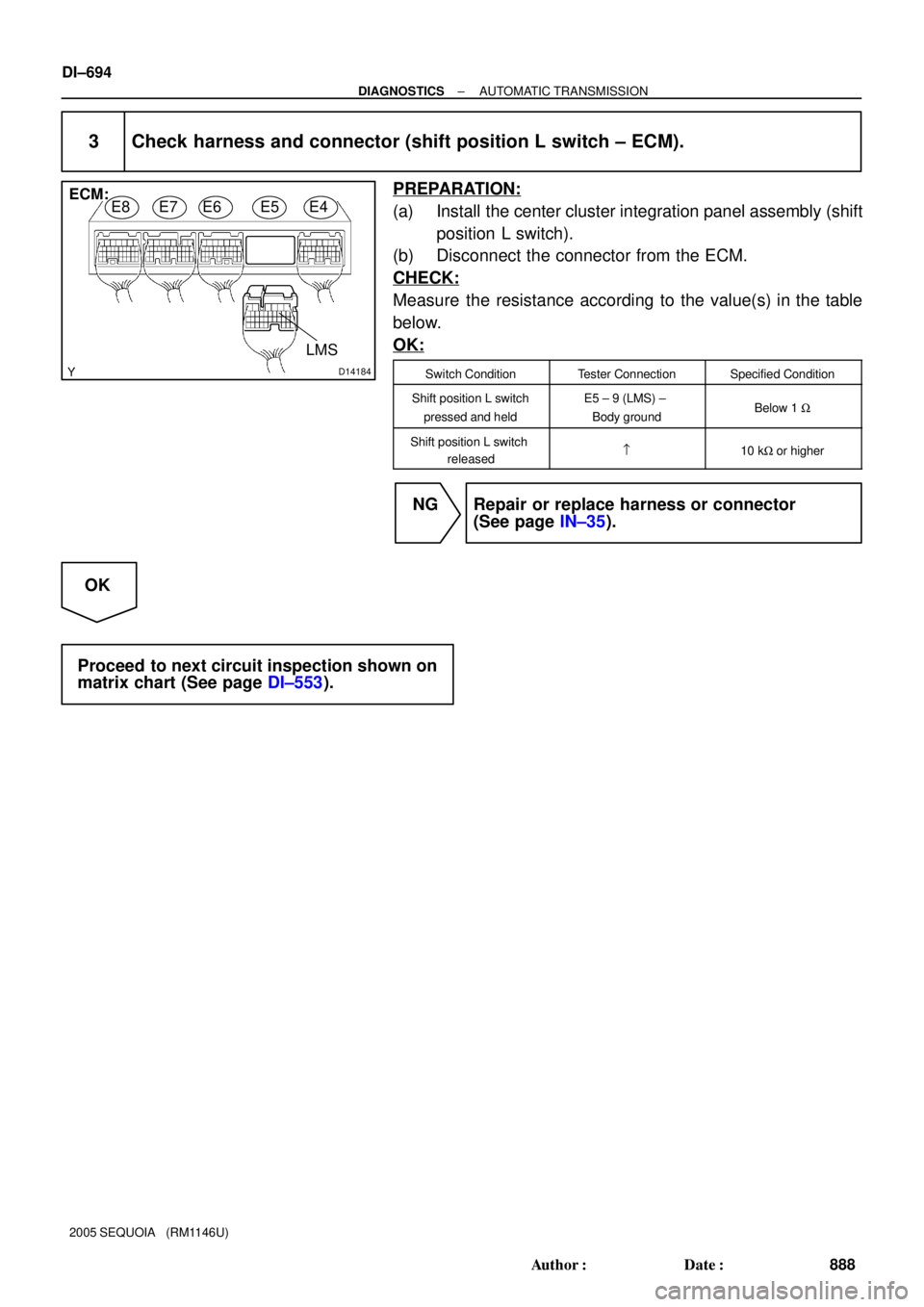
3 Check harness and connector (shift position L switch ± ECM).
PREPARATION:
(a) Install the center cluster integration panel assembly (shift
position L switch).
(b) Disconnect the connector from the ECM.
CHECK:
Measure the resistance according to the value(s) in the table
below.
OK:
Switch ConditionTester ConnectionSpecified Condition
Shift position L switch
pressed and heldE5 ± 9 (LMS) ±
Body groundBelow 1 W
Shift position L switch
released=10 kW or higher
NG Repair or replace harness or connector
(See page IN±35).
OK
Proceed to next circuit inspection shown on
matrix chart (See page DI±553).
Page 897 of 4323
DIDCB±01
± DIAGNOSTICSAIR SUSPENSION SYSTEM
DI±695
889 Author�: Date�:
2005 SEQUOIA (RM1146U)
AIR SUSPENSION SYSTEM
PRECAUTION
Be sure to switch the height control mode select switch to manual mode and cancel the auto leveling
function when:
�Jacking up the vehicle.
�A trailer etc. is attached to the vehicle.
NOTICE:
When disconnecting the battery terminal, initialize the following system after the terminal is recon-
nected.
System NameSee Page
Back Door Power Window Control SystemBE±77
Page 909 of 4323
DIDCP±01
± DIAGNOSTICSAIR SUSPENSION SYSTEM
DI±707
901 Author�: Date�:
2005 SEQUOIA (RM1146U)
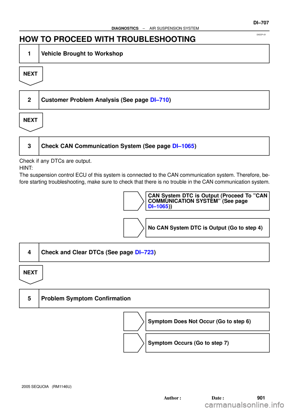
HOW TO PROCEED WITH TROUBLESHOOTING
1 Vehicle Brought to Workshop
NEXT
2 Customer Problem Analysis (See page DI±710)
NEXT
3 Check CAN Communication System (See page DI±1065)
Check if any DTCs are output.
HINT:
The suspension control ECU of this system is connected to the CAN communication system. Therefore, be-
fore starting troubleshooting, make sure to check that there is no trouble in the CAN communication system.
CAN System DTC is Output (Proceed To ºCAN
COMMUNICATION SYSTEMº (See page
DI±1065))
No CAN System DTC is Output (Go to step 4)
4 Check and Clear DTCs (See page DI±723)
NEXT
5 Problem Symptom Confirmation
Symptom Does Not Occur (Go to step 6)
Symptom Occurs (Go to step 7)
Page 910 of 4323
DI±708
± DIAGNOSTICSAIR SUSPENSION SYSTEM
902 Author�: Date�:
2005 SEQUOIA (RM1146U)
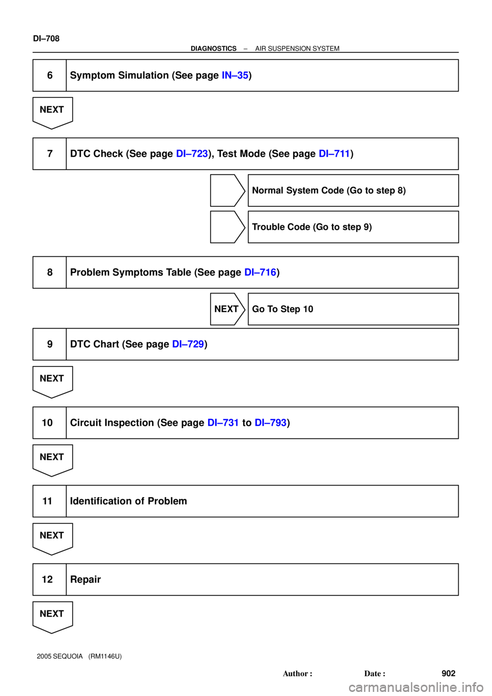
6 Symptom Simulation (See page IN±35)
NEXT
7 DTC Check (See page DI±723), Test Mode (See page DI±711)
Normal System Code (Go to step 8)
Trouble Code (Go to step 9)
8 Problem Symptoms Table (See page DI±716)
NEXT Go To Step 10
9 DTC Chart (See page DI±729)
NEXT
10 Circuit Inspection (See page DI±731 to DI±793)
NEXT
11 Identification of Problem
NEXT
12 Repair
NEXT
Page 913 of 4323

TEST MODE PROCEDURE
1. INPUT SIGNAL")
DIDCV±01
C00083
DLC3
CG TS
F16800
Height
Control
Manual
Indicator
Lamp
± DIAGNOSTICSAIR SUSPENSION SYSTEM
DI±711
905 Author�: Date�:
2005 SEQUOIA (RM1146U)
TEST MODE PROCEDURE
1. INPUT SIGNAL CHECK (Using SST check wire)
HINT:
�This function checks if signals from the stop light switch
assy and the door courtesy lamp switch, etc. are being in-
put normally to the ECU.
�When entering test mode, the suspension control ECU
sets all the test mode DTCs first.
After completing the test mode for each check item, the
test mode DTCs that are determined normal by the sus-
pension control ECU will be erased.
The test mode DTCs for other check items may not be
erased when only a certain signal is inspected.
�When the test mode returns back to normal mode, all the
test mode DTCs will be erased.
(a) Procedure for Input Signal Check Mode (Test Mode) us-
ing SST check wire.
SST 09843±18040
(1) Make sure the ignition switch is OFF.
(2) Set each of the check items to the condition shown
under Operation (A) in the test mode table on the
next page.
(3) Using SST, connect terminals TS and CG of the
DLC3.
(4) Turn the ignition switch to the ON position.
(5) Check that the height control manual indicator lamp
is blinking.
HINT:
�The height control manual indicator lamp comes on for 2
seconds, then blinks at 0.25 sec. intervals.
�If the height control manual indicator light does not blink,
inspect the height control manual indicator lamp circuit
(See page DI±789).
Page 915 of 4323

HINT:
�As ex")
F16802
0.25 sec. 0.5 sec.
ON
OFF
0.25 sec.4.5 sec.
ON
OFF1.5 sec. Normal:
Code 82:
0.5 sec.
Repeat
± DIAGNOSTICSAIR SUSPENSION SYSTEM
DI±713
907 Author�: Date�:
2005 SEQUOIA (RM1146U)
HINT:
�As examples, the blinking patterns of a normal system
code and code 82 are shown in the illustration.
�If 2 or more malfunctions are indicated at the same time,
the lowest numbered code is displayed first.
�When a DTC is not output, check the TC terminal circuit
on page DI±1567.
(9) Check the malfunction using the code table on the
next page.
(b) Ending the Input Signal Check Mode (Test Mode) using
SST check wire.
SST 09843±18040
(1) With the ignition switch OFF, disconnect the SST
check wire from the terminals of the DLC3 and then
turn the ignition switch to the ON position.
(c) Procedure for Sensor Test Mode (Test Mode) using the
hand±held tester.
(1) Make sure the ignition switch is OFF.
(2) Set each of the check items to the condition shown
under Operation (A) in the test mode table on the
previous page.
(3) Connect the hand±held tester to the DLC3.
(4) Turn the ignition switch to the ON position.
(5) Select SIGNAL CHECK mode on the hand±held
tester.
(6) Set each of the check items to the condition shown
under Operation (B) in the test mode table on the
previous page.
HINT:
In step (6), all signals can be checked together.
(7) Read the DTCs by following the prompts on the tes-
ter screen.
HINT:
Refer to the hand±held tester operator's manual for further de-
tails.
Page 916 of 4323

DTC of air suspension system test mode (input signal check) function:
If a troubl")
A08841
Hand±held
Tester
DLC3
DI±714
± DIAGNOSTICSAIR SUSPENSION SYSTEM
908 Author�: Date�:
2005 SEQUOIA (RM1146U)
DTC of air suspension system test mode (input signal check) function:
If a trouble code is displayed during the test mode DTC check, check the circuit listed for that code. For details
of each code, refer to ºSee pageº under the respective DTC No. in the chart.
DTC No.
(See Page)Detection ItemTrouble Area
C1782/82
(DI±767)Stop light switch circuit malfunction
�Stop light switch assy
�Stop light switch circuit
�Suspension control ECU
C1783/83
(DI±770)Door courtesy switch circuit malfunction
�Door courtesy light switch assy
�W/ Motor back door assy
�Door courtesy light switch circuit
�Body ECU
�Back door ECU
�Suspension control ECU
C1786/86
(DI±774)Height control switch circuit malfunction
�Height control switch
�Height control switch circuit
�Suspension control ECU
C1788/88
(DI±778)Height control mode select switch circuit malfunction
�Height control mode select switch
�Height control mode select switch circuit
�Suspension control ECU
2. INPUT SIGNAL CHECK (Using Hand±held Tester)
HINT:
�This function checks if signals from the stop light switch
assy and the door courtesy lamp switch, etc. are being in-
put normally to the ECU.
�When entering test mode, the suspension control ECU
sets all the test mode DTCs first.
After completing the test mode for each check item, the
test mode DTCs that are determined normal by the sus-
pension control ECU will be erased.
The test mode DTCs for other check items may not be
erased when only a certain signal is inspected.
�When the test mode returns back to normal mode, all the
test mode DTCs will be erased.
(a) Procedure for Test Mode (Input signal check).
(1) Make sure that the ignition switch is off.
(2) Set each of the check items to the condition shown
under Operation (A) in the test mode table on the
next page.
(3) Connect the hand±held tester to the DLC3.
(4) Turn the ignition switch to the ON position.
(5) Select TEST MODE mode on the hand±held tester.
(6) Set each of the check items to the condition shown
under Operation (B) in the test mode table below.