Page 880 of 4323
D12795
12
(±)(+)
12
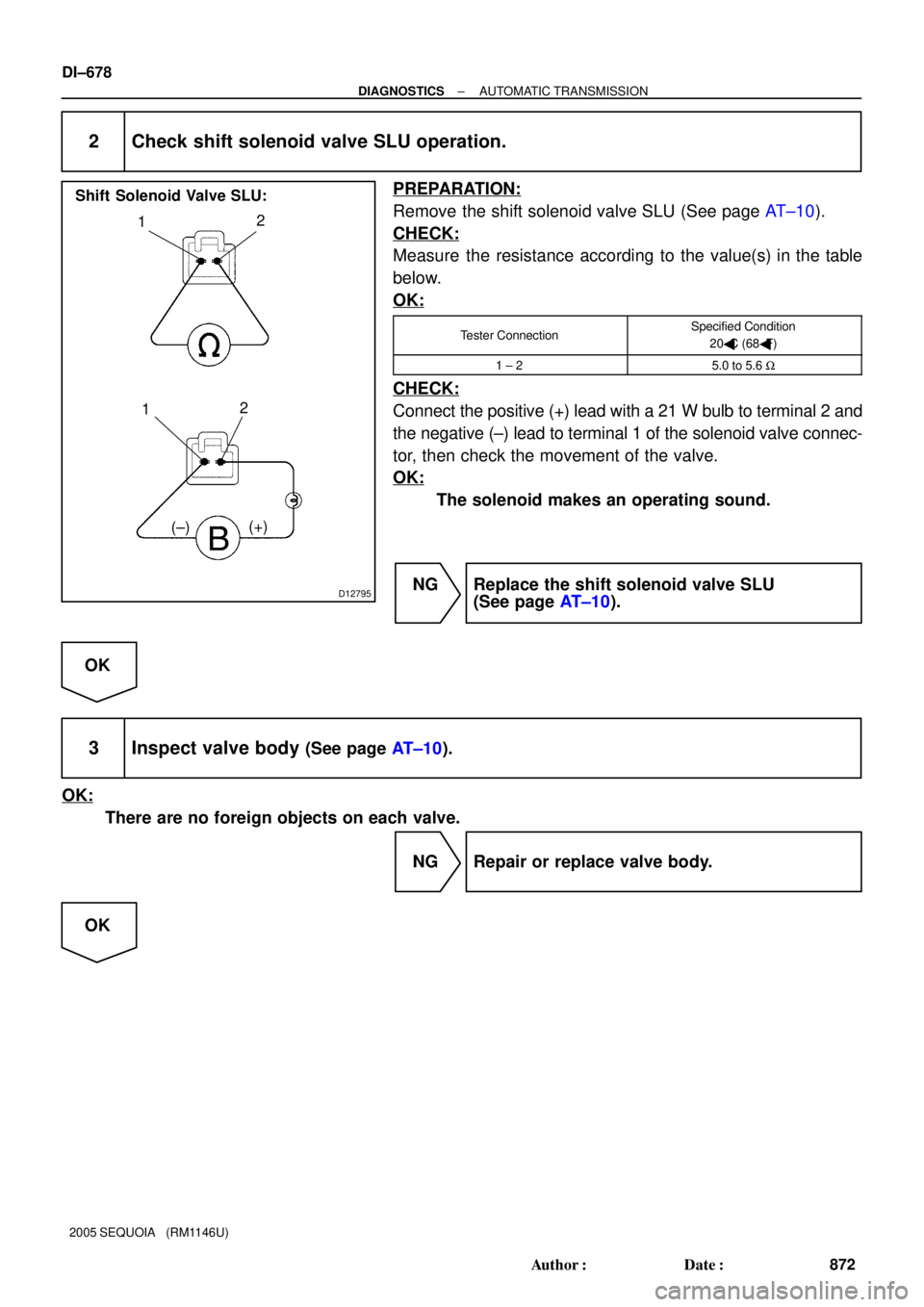
Shift Solenoid Valve SLU:
DI±678
± DIAGNOSTICSAUTOMATIC TRANSMISSION
872 Author�: Date�:
2005 SEQUOIA (RM1146U)
2 Check shift solenoid valve SLU operation.
PREPARATION:
Remove the shift solenoid valve SLU (See page AT±10).
CHECK:
Measure the resistance according to the value(s) in the table
below.
OK:
Tester ConnectionSpecified Condition
20�C (68�F)
1 ± 25.0 to 5.6 W
CHECK:
Connect the positive (+) lead with a 21 W bulb to terminal 2 and
the negative (±) lead to terminal 1 of the solenoid valve connec-
tor, then check the movement of the valve.
OK:
The solenoid makes an operating sound.
NG Replace the shift solenoid valve SLU
(See page AT±10).
OK
3 Inspect valve body (See page AT±10).
OK:
There are no foreign objects on each valve.
NG Repair or replace valve body.
OK
Page 881 of 4323
± DIAGNOSTICSAUTOMATIC TRANSMISSION
DI±679
873 Author�: Date�:
2005 SEQUOIA (RM1146U)
4 Check torque converter clutch (See page AT±30).
OK:
The torque converter clutch operates normally.
NG Replace the torque converter clutch
(See page AT±25).
OK
Repair or replace transmission (See page
AT±25).
Page 883 of 4323
D14178
Electronically Controlled
Transmission Solenoid
E7ECM
E7 P±L
L±W15
14SLU+
SLU± 13 LG
BR
SLU± SLU+ E1
+B
5
± DIAGNOSTICSAUTOMATIC TRANSMISSION
DI±681
875 Author�: Date�:
2005 SEQUOIA (RM1146U)
TYPICAL ENABLING CONDITIONS
ItSpecificationItemMinimumMaximum
The monitor will run whenever this DTC is
not present.See page DI±545
Solenoid current cut statusNot cut
CPU commanded duty19% or more±
Battery voltage11 V or more±
Ignition switchON
StarterOFF
TYPICAL MALFUNCTION THRESHOLDS
Detection criteriaThreshold
Solenoid status from ICFail (Open or short)
COMPONENT OPERATING RANGE
ParameterStandard value
Output signal dutyLess than 100%
WIRING DIAGRAM
Page 885 of 4323
D14166
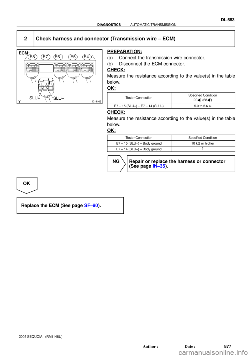
ECM:
SLU+
SLU±E8E7E6E5E4
± DIAGNOSTICSAUTOMATIC TRANSMISSION
DI±683
877 Author�: Date�:
2005 SEQUOIA (RM1146U)
2 Check harness and connector (Transmission wire ± ECM)
PREPARATION:
(a) Connect the transmission wire connector.
(b) Disconnect the ECM connector.
CHECK:
Measure the resistance according to the value(s) in the table
below.
OK:
Tester ConnectionSpecified Condition
20�C (68�F)
E7 ± 15 (SLU+) ± E7 ± 14 (SLU±)5.0 to 5.6 W
CHECK:
Measure the resistance according to the value(s) in the table
below.
OK:
Tester ConnectionSpecified Condition
E7 ± 15 (SLU+) ± Body ground10 kW or higher
E7 ± 14 (SLU±) ± Body ground=
NG Repair or replace the harness or connector
(See page IN±35).
OK
Replace the ECM (See page SF±80).
Page 886 of 4323
D12795
12
(±)(+)
12
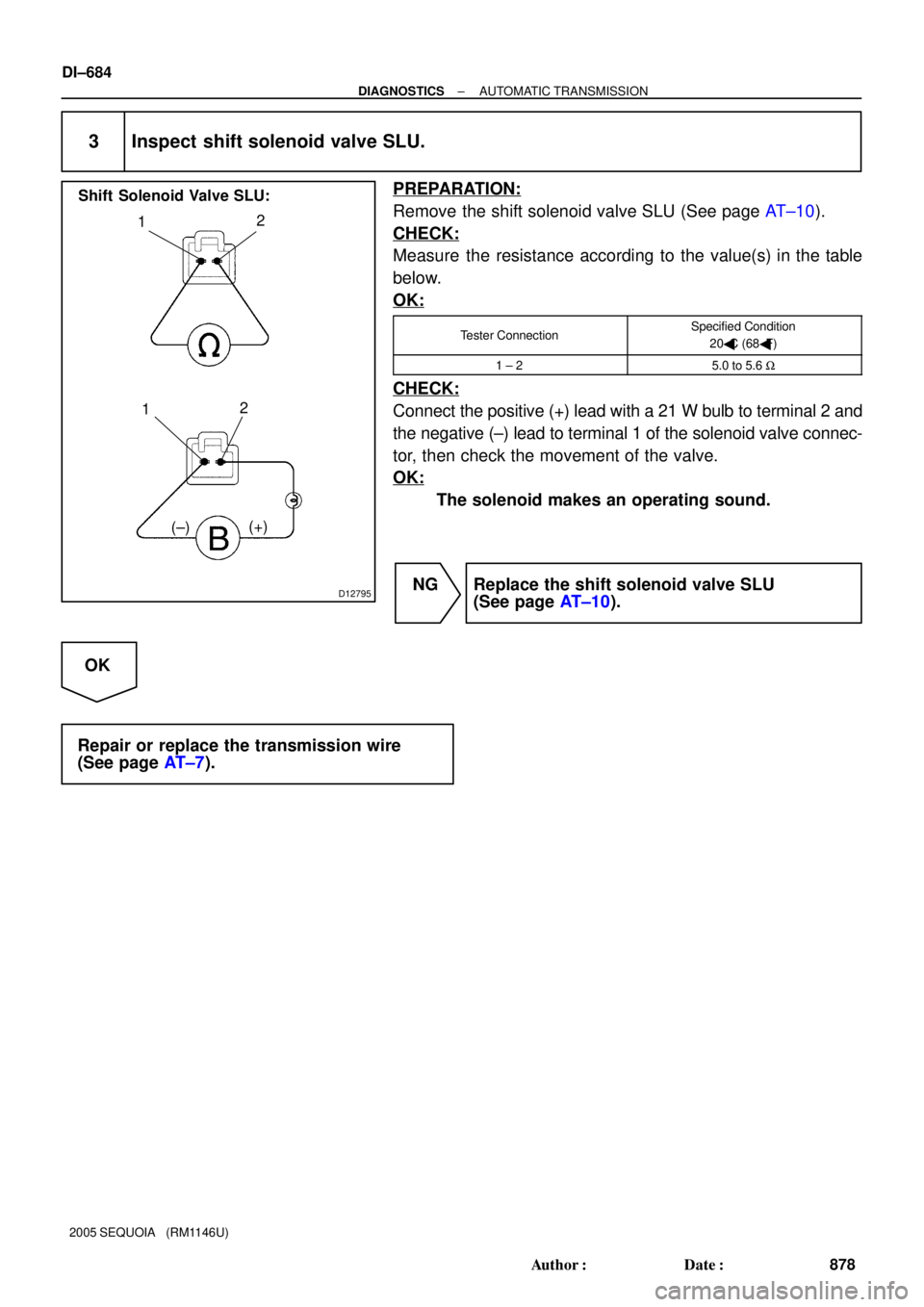
Shift Solenoid Valve SLU:
DI±684
± DIAGNOSTICSAUTOMATIC TRANSMISSION
878 Author�: Date�:
2005 SEQUOIA (RM1146U)
3 Inspect shift solenoid valve SLU.
PREPARATION:
Remove the shift solenoid valve SLU (See page AT±10).
CHECK:
Measure the resistance according to the value(s) in the table
below.
OK:
Tester ConnectionSpecified Condition
20�C (68�F)
1 ± 25.0 to 5.6 W
CHECK:
Connect the positive (+) lead with a 21 W bulb to terminal 2 and
the negative (±) lead to terminal 1 of the solenoid valve connec-
tor, then check the movement of the valve.
OK:
The solenoid makes an operating sound.
NG Replace the shift solenoid valve SLU
(See page AT±10).
OK
Repair or replace the transmission wire
(See page AT±7).
Page 889 of 4323
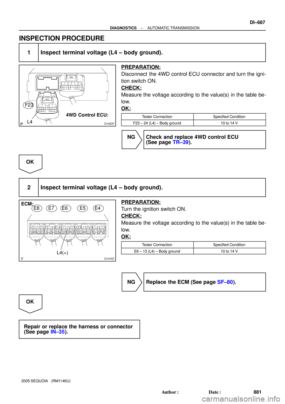
D14237L4
4WD Control ECU: F23
D14167
ECM:
E8E7E6E5E4
L4(+)
± DIAGNOSTICSAUTOMATIC TRANSMISSION
DI±687
881 Author�: Date�:
2005 SEQUOIA (RM1146U)
INSPECTION PROCEDURE
1 Inspect terminal voltage (L4 ± body ground).
PREPARATION:
Disconnect the 4WD control ECU connector and turn the igni-
tion switch ON.
CHECK:
Measure the voltage according to the value(s) in the table be-
low.
OK:
Tester ConnectionSpecified Condition
F23 ± 24 (L4) ± Body ground10 to 14 V
NG Check and replace 4WD control ECU
(See page TR±39).
OK
2 Inspect terminal voltage (L4 ± body ground).
PREPARATION:
Turn the ignition switch ON.
CHECK:
Measure the voltage according to the value(s) in the table be-
low.
OK:
Tester ConnectionSpecified Condition
E6 ± 13 (L4) ± Body ground10 to 14 V
NG Replace the ECM (See page SF±80).
OK
Repair or replace the harness or connector
(See page IN±35).
Page 891 of 4323
D14181
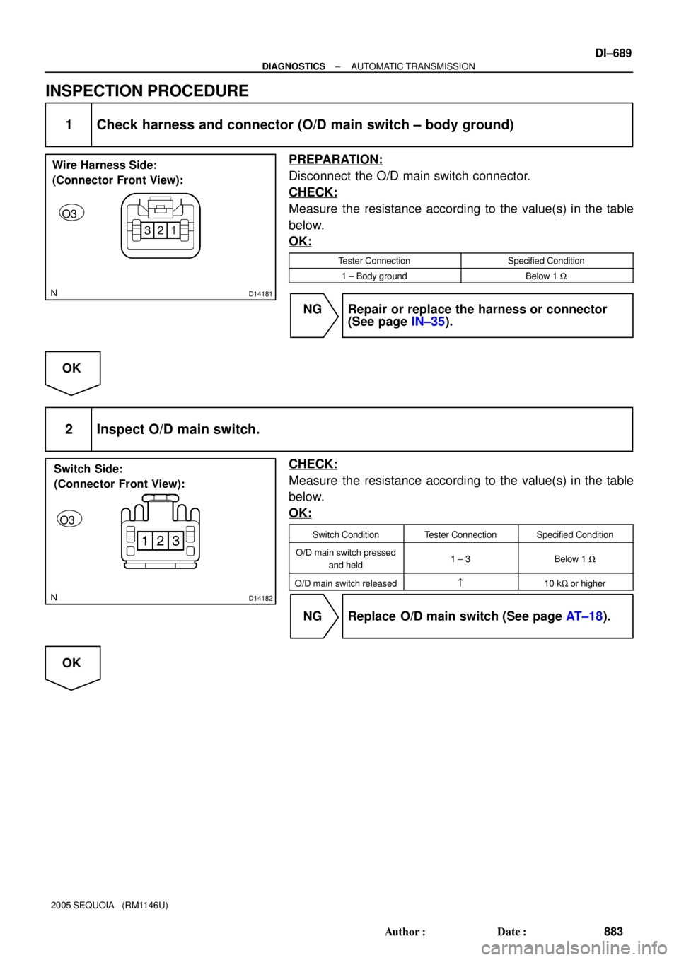
Wire Harness Side:
(Connector Front View):
O3
D14182
Switch Side:
(Connector Front View):
O3
± DIAGNOSTICSAUTOMATIC TRANSMISSION
DI±689
883 Author�: Date�:
2005 SEQUOIA (RM1146U)
INSPECTION PROCEDURE
1 Check harness and connector (O/D main switch ± body ground)
PREPARATION:
Disconnect the O/D main switch connector.
CHECK:
Measure the resistance according to the value(s) in the table
below.
OK:
Tester ConnectionSpecified Condition
1 ± Body groundBelow 1 W
NG Repair or replace the harness or connector
(See page IN±35).
OK
2 Inspect O/D main switch.
CHECK:
Measure the resistance according to the value(s) in the table
below.
OK:
Switch ConditionTester ConnectionSpecified Condition
O/D main switch pressed
and held1 ± 3Below 1 W
O/D main switch released=10 kW or higher
NG Replace O/D main switch (See page AT±18).
OK
Page 892 of 4323
D14183
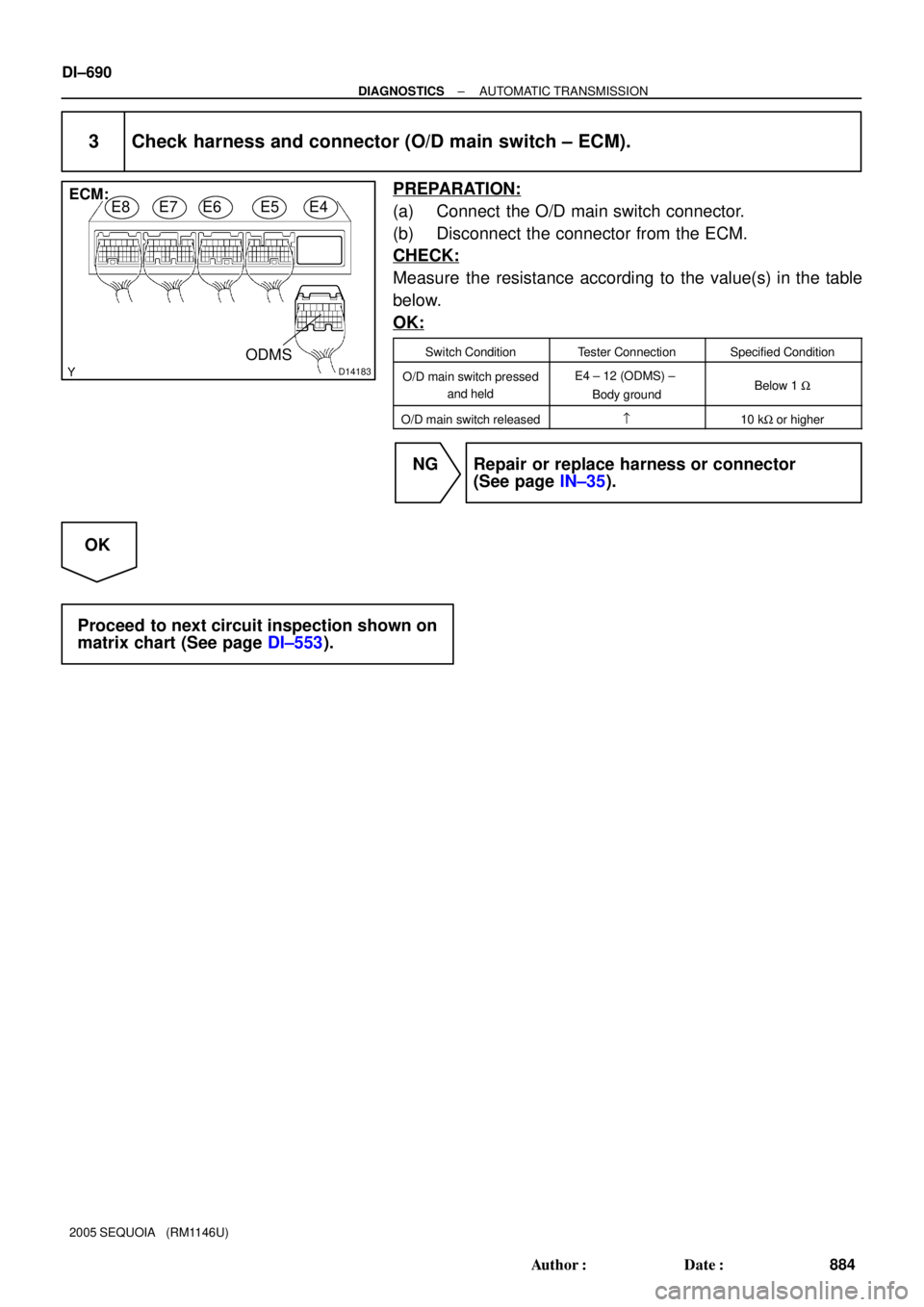
E8E7E6E5E4ECM:
ODMS
DI±690
± DIAGNOSTICSAUTOMATIC TRANSMISSION
884 Author�: Date�:
2005 SEQUOIA (RM1146U)
3 Check harness and connector (O/D main switch ± ECM).
PREPARATION:
(a) Connect the O/D main switch connector.
(b) Disconnect the connector from the ECM.
CHECK:
Measure the resistance according to the value(s) in the table
below.
OK:
Switch ConditionTester ConnectionSpecified Condition
O/D main switch pressed
and heldE4 ± 12 (ODMS) ±
Body groundBelow 1 W
O/D main switch released=10 kW or higher
NG Repair or replace harness or connector
(See page IN±35).
OK
Proceed to next circuit inspection shown on
matrix chart (See page DI±553).