Page 842 of 4323
DI±640
± DIAGNOSTICSAUTOMATIC TRANSMISSION
834 Author�: Date�:
2005 SEQUOIA (RM1146U)
3 Clear the DTC and running test.
CHECK:
Clear the DTC, and check DTC again after conducting the ºMONITOR DRIVE PATTERN FOR ECT TESTº
(See page DI±551).
OK:
No DTC code
NG Repair or replace valve body
(See page AT±10).
OK
END
Page 843 of 4323

DTC P0973 Shift Solenoid ºAº Control Circuit Low
(Shift Solenoid Valve S1)
DTC P0974 Shift Solenoid ºAº Co")
± DIAGNOSTICSAUTOMATIC TRANSMISSION
DI±641
835 Author�: Date�:
2005 SEQUOIA (RM1146U)
DTC P0973 Shift Solenoid ºAº Control Circuit Low
(Shift Solenoid Valve S1)
DTC P0974 Shift Solenoid ºAº Control Circuit High
(Shift Solenoid Valve S1)
CIRCUIT DESCRIPTION
Shifting from 1st to 5th is performed in combination with ºONº and ºOFFº operation of the shift solenoid valves
SL1, SL2, S1, S2 and SR which are controlled by the ECM. If an open or short circuit occurs in either of the
shift solenoid valves, the ECM controls the remaining normal shift solenoid valves to allow the vehicle to be
operated smoothly (See page DI±567).
DTC No.DTC Detection ConditionTrouble Area
P0973ECM detects short in solenoid valve S1 circuit 2 times when
solenoid valve S1 is operated (1±trip detection logic)�Short in shift solenoid valve S1 circuit
�Shift solenoid valve S1
�ECM
P0974ECM detects open in solenoid valve S1 circuit 2 times when
solenoid valve S1 is not operated (1±trip detection logic)�Open in shift solenoid valve S1 circuit
�Shift solenoid valve S1
�ECM
MONITOR DESCRIPTION
These DTCs indicate an open or short in the shift solenoid valve S1 circuit. When there is an open or short
circuit in any shift solenoid valve circuit, the ECM detects the problem and illuminates the MIL and stores
the DTC. When the shift solenoid valve S1 is on, if resistance is 8 W or less, the ECM determines there is
a short in the shift solenoid valve S1 circuit.
When the shift solenoid valve S1 is off, if resistance is 100 kW or more, the ECM determines there is an open
in the shift solenoid valve S1 circuit (See page DI±567).
MONITOR STRATEGY
RltdDTCP0973Shift solenoid valve S1/Range check (Low resistance)Related DTCsP0974Shift solenoid valve S1/Range check (High resistance)
Required sensors/ComponentsShift solenoid valve S1
Frequency of operationContinuous
Duration0.064 sec.
MIL operationImmediate
Sequence of operationNone
DIDJI±01
Page 844 of 4323
D14170
E1
Electronically Controlled
Transmission SolenoidECM
11
E7S1
8 W
R
S1+B
CPU
DI±642
± DIAGNOSTICSAUTOMATIC TRANSMISSION
836 Author�: Date�:
2005 SEQUOIA (RM1146U)
TYPICAL ENABLING CONDITIONS
ItSpecificationItemMinimumMaximum
The monitor will run whenever these
DTCs are not present.See page DI±545
Range check (Low resistance)
Shift solenoid valve S1ON
Range check (High resistance)
Shift solenoid valve S1OFF
TYPICAL MALFUNCTION THRESHOLDS
Detection criteriaThreshold
Range check (Low resistance)
Shift solenoid valve S1 resistance8 W or less
Range check (High resistance)
Shift solenoid valve S1 resistance100 kW or more
COMPONENT OPERATING RANGE
ParameterStandard value
Shift solenoid valve S1Resistance: 11 to 15 W at 20°C (68°F)
WIRING DIAGRAM
Page 846 of 4323
D14166
ECM:
E8E7E6E5E4
S1
DI±644
± DIAGNOSTICSAUTOMATIC TRANSMISSION
838 Author�: Date�:
2005 SEQUOIA (RM1146U)
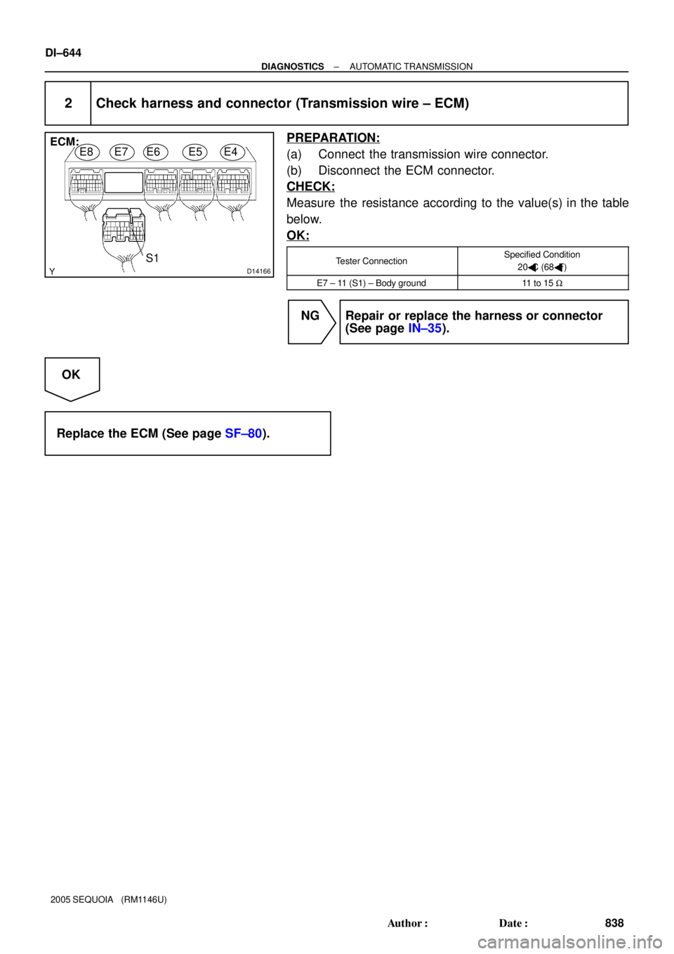
2 Check harness and connector (Transmission wire ± ECM)
PREPARATION:
(a) Connect the transmission wire connector.
(b) Disconnect the ECM connector.
CHECK:
Measure the resistance according to the value(s) in the table
below.
OK:
Tester ConnectionSpecified Condition
20�C (68�F)
E7 ± 11 (S1) ± Body ground11 to 15 W
NG Repair or replace the harness or connector
(See page IN±35).
OK
Replace the ECM (See page SF±80).
Page 847 of 4323
D11991(+) (±)
Shift Solenoid Valve S1:
± DIAGNOSTICSAUTOMATIC TRANSMISSION
DI±645
839 Author�: Date�:
2005 SEQUOIA (RM1146U)
3 Check shift solenoid valve S1.
PREPARATION:
Remove the shift solenoid valve S1 (See page AT±10).
CHECK:
Measure the resistance according to the value(s) in the table
below.
OK:
Tester ConnectionSpecified Condition
20�C (68�F)
Solenoid Connector (S1) ± Solenoid
Body (S1)11 to 15 W
CHECK:
Connect the positive (+) lead to the terminal of the solenoid con-
nector, and the negative (±) lead to the solenoid body.
OK:
The solenoid makes an operating sound.
NG Replace the shift solenoid valve S1
(See page AT±10).
OK
Repair or replace the transmission wire
(See page AT±7).
Page 848 of 4323

DTC P0976 Shift Solenoid ºBº Control Circuit Low
(Shift Solenoid Valve S2)
DTC P0977 Shift Solenoid ºBº Co")
DI±646
± DIAGNOSTICSAUTOMATIC TRANSMISSION
840 Author�: Date�:
2005 SEQUOIA (RM1146U)
DTC P0976 Shift Solenoid ºBº Control Circuit Low
(Shift Solenoid Valve S2)
DTC P0977 Shift Solenoid ºBº Control Circuit High
(Shift Solenoid Valve S2)
CIRCUIT DESCRIPTION
Shifting from 1st to 5th is performed in combination with ºONº and ºOFFº operation of the shift solenoid valves
SL1, SL2, S1, S2 and SR which are controlled by the ECM. If an open or short circuit occurs in either of the
shift solenoid valves, the ECM controls the remaining normal shift solenoid valves to allow the vehicle to be
operated smoothly (See page DI±567).
DTC No.DTC Detection ConditionTrouble Area
P0976ECM detects short in solenoid valve S2 circuit 2 times when
solenoid valve S2 is operated (1±trip detection logic)�Short in shift solenoid valve S2 circuit
�Shift solenoid valve S2
�ECM
P0977ECM detects open in solenoid valve S2 circuit 2 times when
solenoid valve S2 is not operated (1±trip detection logic)�Open in shift solenoid valve S2 circuit
�Shift solenoid valve S2
�ECM
MONITOR DESCRIPTION
These DTCs indicate an open or short in the shift solenoid valve S2 circuit. When there is an open or short
circuit in any shift solenoid valve circuit, the ECM detects the problem and illuminates the MIL and stores
the DTC. When the shift solenoid valve S2 is on, if resistance is 8 W or less, the ECM determines there is
a short in the shift solenoid valve S2 circuit.
When the shift solenoid valve S2 is off, if resistance is 100 kW or more, the ECM determines there is an open
in the shift solenoid valve S2 circuit (See page DI±567).
MONITOR STRATEGY
RltdDTCP0976Shift solenoid valve S2/Range check (Low resistance)Related DTCsP0977Shift solenoid valve S2/Range check (High resistance)
Required sensors/ComponentsShift solenoid valve S2
Frequency of operationContinuous
Duration0.064 sec.
MIL operationImmediate
Sequence of operationNone
DIDJJ±01
Page 849 of 4323
D14170
E1
Electronically Controlled
Transmission SolenoidECM
10
E7S2
15 B
W±L
S2+B
CPU
± DIAGNOSTICSAUTOMATIC TRANSMISSION
DI±647
841 Author�: Date�:
2005 SEQUOIA (RM1146U)
TYPICAL ENABLING CONDITIONS
ItSpecificationItemMinimumMaximum
The monitor will run whenever these
DTCs are not present.See page DI±545
Range check (Low resistance)
Shift solenoid valve S2ON
Range check (High resistance)
Shift solenoid valve S2OFF
TYPICAL MALFUNCTION THRESHOLDS
Detection criteriaThreshold
Range check (Low resistance)
Shift solenoid valve S2 resistance8 W or less
Range check (High resistance)
Shift solenoid valve S2 resistance100 kW or more
COMPONENT OPERATING RANGE
ParameterStandard value
Shift solenoid valve S2Resistance: 11 to 15 W at 20°C (68°F)
WIRING DIAGRAM
Page 851 of 4323
D14166
ECM:
E8E7E6E5E4
S2
± DIAGNOSTICSAUTOMATIC TRANSMISSION
DI±649
843 Author�: Date�:
2005 SEQUOIA (RM1146U)
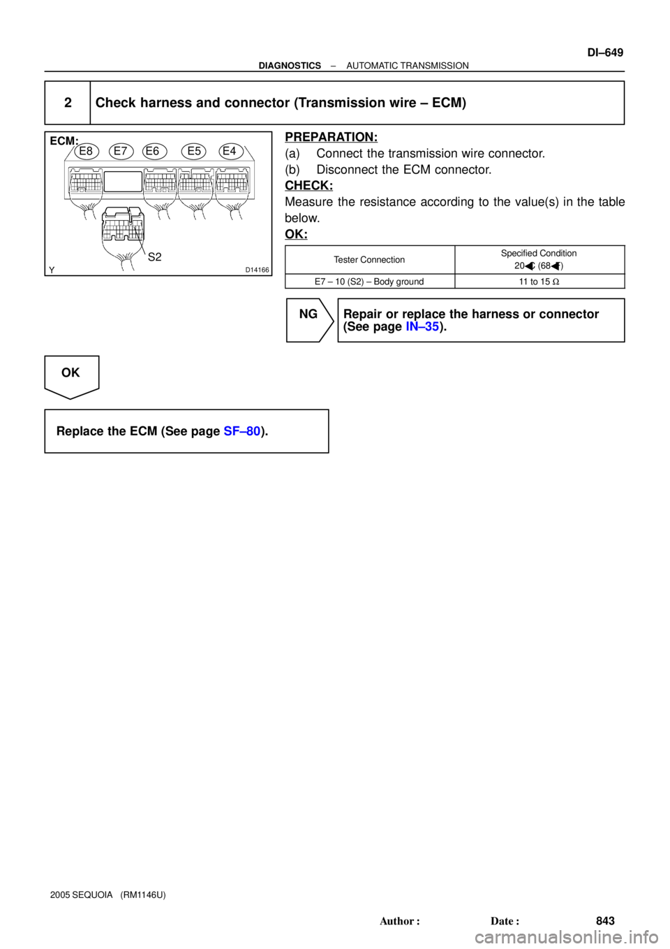
2 Check harness and connector (Transmission wire ± ECM)
PREPARATION:
(a) Connect the transmission wire connector.
(b) Disconnect the ECM connector.
CHECK:
Measure the resistance according to the value(s) in the table
below.
OK:
Tester ConnectionSpecified Condition
20�C (68�F)
E7 ± 10 (S2) ± Body ground11 to 15 W
NG Repair or replace the harness or connector
(See page IN±35).
OK
Replace the ECM (See page SF±80).