Page 1947 of 4323
± DIAGNOSTICSBODY CONTROL SYSTEM
DI±1745
1939 Author�: Date�:
2005 SEQUOIA (RM1146U)
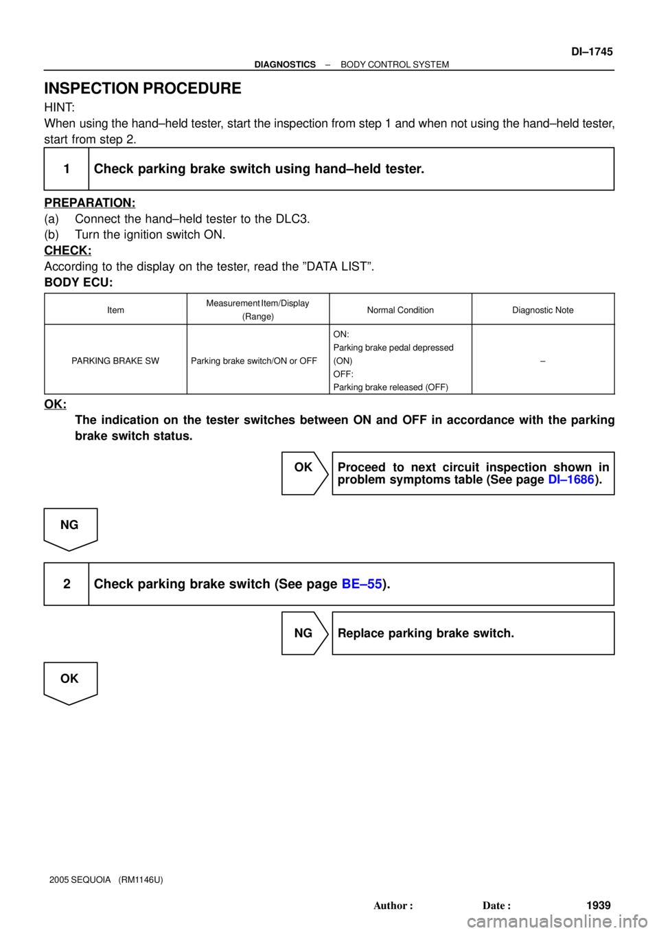
INSPECTION PROCEDURE
HINT:
When using the hand±held tester, start the inspection from step 1 and when not using the hand±held tester,
start from step 2.
1 Check parking brake switch using hand±held tester.
PREPARATION:
(a) Connect the hand±held tester to the DLC3.
(b) Turn the ignition switch ON.
CHECK:
According to the display on the tester, read the ºDATA LISTº.
BODY ECU:
ItemMeasurement Item/Display
(Range)Normal ConditionDiagnostic Note
PARKING BRAKE SWParking brake switch/ON or OFF
ON:
Parking brake pedal depressed
(ON)
OFF:
Parking brake released (OFF)
±
OK:
The indication on the tester switches between ON and OFF in accordance with the parking
brake switch status.
OK Proceed to next circuit inspection shown in
problem symptoms table (See page DI±1686).
NG
2 Check parking brake switch (See page BE±55).
NG Replace parking brake switch.
OK
Page 1950 of 4323

INSPECTION PROCEDURE
HINT:
When using the hand±held tester, start the inspection from step 1 and when not usin")
DI±1748
± DIAGNOSTICSBODY CONTROL SYSTEM
1942 Author�: Date�:
2005 SEQUOIA (RM1146U)
INSPECTION PROCEDURE
HINT:
When using the hand±held tester, start the inspection from step 1 and when not using the hand±held tester,
start from step 2.
1 Check rear power window motor using hand±held tester.
PREPARATION:
(a) Connect the hand±held tester to the DLC3.
(b) Turn the ignition switch ON.
CHECK:
According to the display on the tester, perform the ºACTIVE TESTº.
BODY ECU:
ItemTest DetailsDiagnostic Note
RL P/W UP/DOWNRear left passenger power window DOWN/UPCaution: This test causes vehicle parts to move.
Watch your hands and feet.
RR P/W UP/DOWNRear right passenger power window DOWN/UPCaution: This test causes vehicle parts to move.
Watch your hands and feet.
OK:
The rear power windows go up or down correctly when operating them through the hand±held
tester.
OK Proceed to next circuit inspection shown in
problem symptoms table (See page DI±1686).
NG
2 Check power window control switch rear (See page BE±69).
NG Replace power window switch rear.
OK
3 Check wire harness and connector between power window control switch rear
and body ECU (See page IN±35).
NG Repair or replace wire harness or connector.
OK
Page 1953 of 4323

INSPECTION PROCEDURE
HINT:
When using the hand±held tester, start the inspection from step 1 and when not usin")
± DIAGNOSTICSBODY CONTROL SYSTEM
DI±1751
1945 Author�: Date�:
2005 SEQUOIA (RM1146U)
INSPECTION PROCEDURE
HINT:
When using the hand±held tester, start the inspection from step 1 and when not using the hand±held tester,
start from step 2.
1 Check headlight control switch using hand±held tester.
PREPARATION:
(a) Connect the hand±held tester to the DLC3.
(b) Turn the ignition switch ON.
CHECK:
According to the display on the tester, read the ºDATA LISTº.
BODY ECU:
ItemMeasurement Item/Display
(Range)Normal ConditionDiagnostic Note
AUTO LIGHT SWLight control switch (AUTO)/ON or
OFF
ON: Light control switch position is
AUTO
OFF: Light control switch position
is not AUTO
±
HEAD LIGHT SWLight control switch (HEAD)/ON or
OFF
ON: Light control switch position is
HEAD
OFF: Light control switch position
is not HEAD
±
TAIL LIGHT SWLight control switch (TAIL)/ON or
OFF
ON: Light control switch position is
TAIL
OFF: Light control switch position
is not TAIL
±
OK:
The indication on the tester switches between ON and OFF in accordance with the light control
switch status.
OK Proceed to next circuit inspection shown in
problem symptoms table (See page DI±1686).
NG
2 Check light control switch (See page BE±27).
NG Replace light control switch.
OK
Page 1956 of 4323

INSPECTION PROCEDURE
1 Check automatic light control sensor.
When using hand±held tester:
PREPARATION:
(a) Con")
DI±1754
± DIAGNOSTICSBODY CONTROL SYSTEM
1948 Author�: Date�:
2005 SEQUOIA (RM1146U)
INSPECTION PROCEDURE
1 Check automatic light control sensor.
When using hand±held tester:
PREPARATION:
(a) Connect the hand±held tester to the DLC3.
(b) Turn the ignition switch and hand±held tester main switch ON.
BODY ECU:
ItemMeasurement Item/Display
(Range)Normal ConditionDiagnostic Note
ILLUMINATE RATEIllumination rate information/
MIN: 0 MAX: 99.99Condition value will be displayed
Normal value: 0.8 ms to 22.0 ms±
CHECK:
The illumination rate value should change within the following range such as when the light sensor is ex-
posed to light or covered by hand.
OK:
0.8 ms to 22.0 ms
HINT:
Time needed for the light sensor to generate one cycle of frequency according to the brightness.
When not using hand±held tester (See page BE±27):
NG Replace automatic light control sensor.
OK
2 Check harness and connector between automatic light control sensor and body
ECU (See page IN±35).
NG Repair or replace wire harness or connector.
OK
Proceed to next inspection shown in problem
symptoms table (See page DI±1686).
Page 1964 of 4323
DI±1762
± DIAGNOSTICSBODY CONTROL SYSTEM
1956 Author�: Date�:
2005 SEQUOIA (RM1146U)
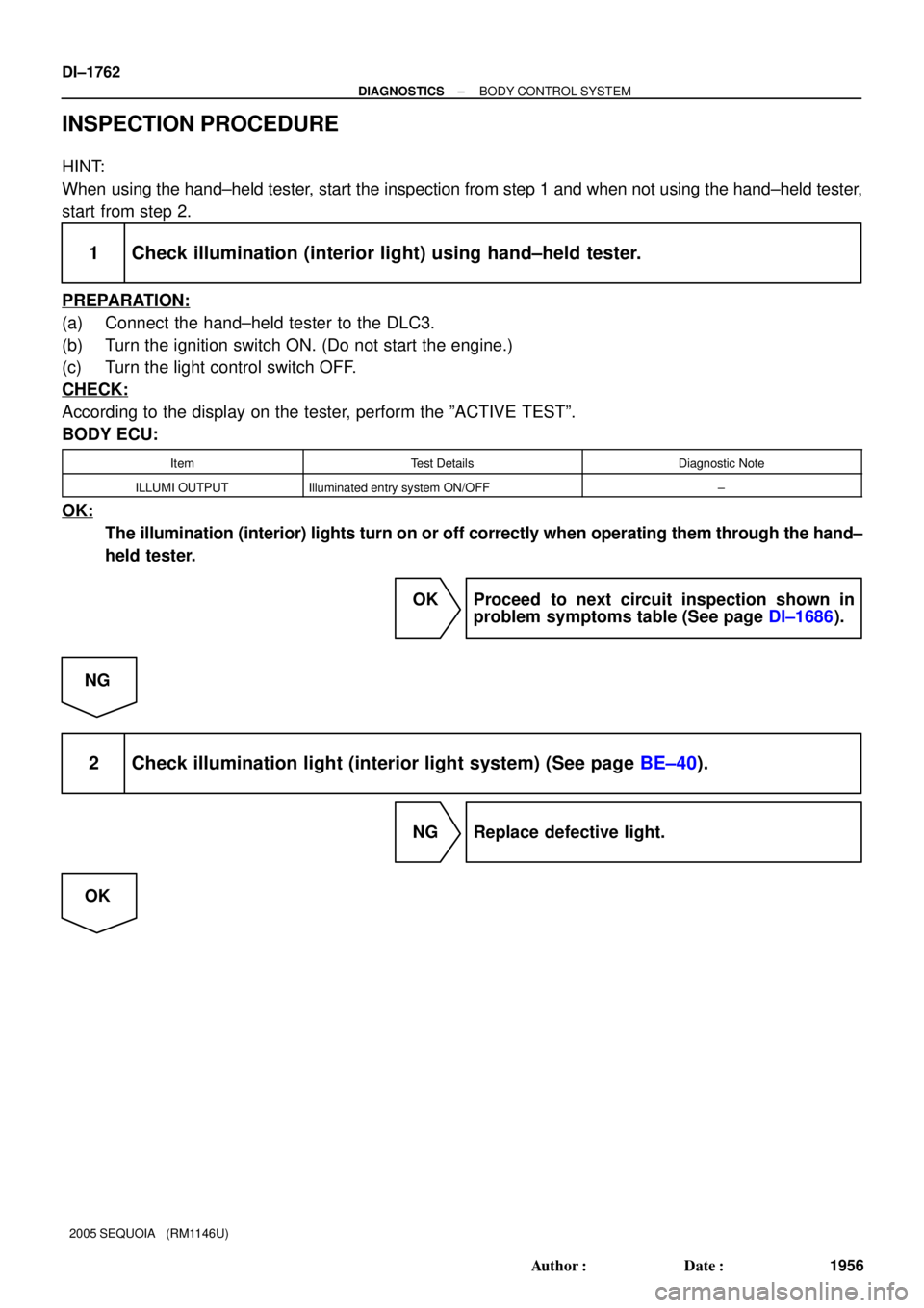
INSPECTION PROCEDURE
HINT:
When using the hand±held tester, start the inspection from step 1 and when not using the hand±held tester,
start from step 2.
1 Check illumination (interior light) using hand±held tester.
PREPARATION:
(a) Connect the hand±held tester to the DLC3.
(b) Turn the ignition switch ON. (Do not start the engine.)
(c) Turn the light control switch OFF.
CHECK:
According to the display on the tester, perform the ºACTIVE TESTº.
BODY ECU:
ItemTest DetailsDiagnostic Note
ILLUMI OUTPUTIlluminated entry system ON/OFF±
OK:
The illumination (interior) lights turn on or off correctly when operating them through the hand±
held tester.
OK Proceed to next circuit inspection shown in
problem symptoms table (See page DI±1686).
NG
2 Check illumination light (interior light system) (See page BE±40).
NG Replace defective light.
OK
Page 1967 of 4323
± DIAGNOSTICSBODY CONTROL SYSTEM
DI±1765
1959 Author�: Date�:
2005 SEQUOIA (RM1146U)
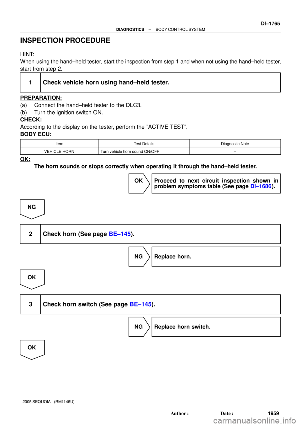
INSPECTION PROCEDURE
HINT:
When using the hand±held tester, start the inspection from step 1 and when not using the hand±held tester,
start from step 2.
1 Check vehicle horn using hand±held tester.
PREPARATION:
(a) Connect the hand±held tester to the DLC3.
(b) Turn the ignition switch ON.
CHECK:
According to the display on the tester, perform the ºACTIVE TESTº.
BODY ECU:
ItemTest DetailsDiagnostic Note
VEHICLE HORNTurn vehicle horn sound ON/OFF±
OK:
The horn sounds or stops correctly when operating it through the hand±held tester.
OK Proceed to next circuit inspection shown in
problem symptoms table (See page DI±1686).
NG
2 Check horn (See page BE±145).
NG Replace horn.
OK
3 Check horn switch (See page BE±145).
NG Replace horn switch.
OK
Page 1971 of 4323

INSPECTION PROCEDURE
HINT:
When using the hand±held tester, start the inspection from step 1 and when not usin")
± DIAGNOSTICSBODY CONTROL SYSTEM
DI±1769
1963 Author�: Date�:
2005 SEQUOIA (RM1146U)
INSPECTION PROCEDURE
HINT:
When using the hand±held tester, start the inspection from step 1 and when not using the hand±held tester,
start from step 2.
1 Check remote mirror control switch using hand±held tester.
PREPARATION:
(a) Connect the hand±held tester to the DLC3.
(b) Turn the ignition switch ON.
CHECK:
According to the display on the tester, read the ºDATA LISTº.
BODY ECU:
ItemMeasurement Item/Display
(Range)Normal ConditionDiagnostic Note
MIRR SEL SW RRemote control mirror switch pas-
senger side/ON or OFF
ON: Remote control mirror switch
passenger side is selected
OFF: Remote control mirror switch
passenger side is not selected
±
MIRR SEL SW LRemote control mirror switch driv-
er side/ON or OFF
ON: Remote control mirror switch
driver side is selected
OFF: Remote control mirror switch
driver side is not selected
±
MIRR POS SW RRemote control mirror switch R
position/ON or OFF
ON: Remote control mirror switch
R position is selected
OFF: Remote control mirror switch
R position is not selected
±
MIRR POS SW LRemote control mirror switch L
position/ON or OFF
ON: Remote control mirror switch
L position is selected
OFF: Remote control mirror switch
L position is not selected
±
MIRR POS SW UPRemote control mirror switch UP
position/ON or OFF
ON: Remote control mirror switch
UP position is selected
OFF: Remote control mirror switch
UP position is not selected
±
MIRR POS SW DWNRemote control mirror switch
DOWN position/ON or OFF
ON: Remote control mirror switch
DOWN position is selected
OFF: Remote control mirror switch
DOWN position is not selected
±
OK:
The indication on the tester switches between ON and OFF in accordance with the remote con-
trol mirror switch status.
OK Proceed to next circuit inspection shown in
problem symptoms table (See page DI±1686).
NG
Page 1987 of 4323

DATA LIST / ACTIVE TEST
1. DATA LIST
HINT:
According to the DATA LIST displayed by the hand±")
DIDEM±01
± DIAGNOSTICSDRIVER DOOR CONTROL SYSTEM
DI±1785
1979 Author�: Date�:
2005 SEQUOIA (RM1146U)
DATA LIST / ACTIVE TEST
1. DATA LIST
HINT:
According to the DATA LIST displayed by the hand±held tester, you can read the value of the switch, sensor,
actuator and so on without parts removal. Reading the DATA LIST as the first step of troubleshooting is one
of the methods to shorten labor time.
(a) Connect the hand±held tester to the DLC3.
(b) Turn the ignition switch ON.
(c) According to the display on the tester, read the DATA LIST.
D±DOOR:
ItemMeasurement Item/Dis-
play (Range)Normal ConditionDiagnostic Note
D P/W AUTO SW
Driver door power win-
dow auto SW signal/
ON or OFFON: Driver door power window auto UP/DOWN SW is ON
OFF: Driver door power window auto UP/DOWN SW is
OFF
±
P P/W AUTO SW
Driver door power win-
dow auto SW signal/
ON or OFFON: Driver door power window auto UP/DOWN SW is ON
OFF: Driver door power window auto UP/DOWN SW is
OFF
±
LIMIT SWJam protection limit SW/
ON or OFFON: Window is almost fully open
OFF: Window is open*1
LOCK POS SWLock position SW signal/
ON or OFFON: Door lock is in unlock position
OFF: Door lock is in lock position±
*1: If the jam protection limit switch is turned ON, the jam protection function will stop.
Even if the switch is not turned ON when the windows are almost fully open, the window will not fully close
as jam protection operates at upper window positions during automatic±up operation.
HINT:
The following data list can be used when the power window is operated through manual±up operation during
the ACTIVE TEST.
ItemMeasurement Item/Display (Range)Normal ConditionDiagnostic Note
GLASS POS±1/4
Detects things caught in the P/W / OK or
CAUTION
(Displayed during the active test)OK: Nothing caught in the range between
fully open and 1/4 open*2
GLASS POS±2/4
Detects things caught in the P/W / OK or
CAUTION
(Displayed during the active test)OK: Nothing caught in the range between
1/4 open and 2/4 open*2
GLASS POS±3/4
Detects things caught in the P/W / OK or
CAUTION
(Displayed during the active test)OK: Nothing caught in the range between
2/4 open and 3/4 open*2
GLASS POS±OPEN
Detects things caught in the P/W / OK or
CAUTION
(Displayed during the active test)OK: Nothing caught in the range between
3/4 open and fully open*2
HINT:
*2: If the CAUTION is displayed without applying any resistance in each range, there must be something
caught somewhere in that range.
ItemMeasurement Item/Display (Range)Normal ConditionDiagnostic Note
UP/DOOR KEY (*1)
Driver door key lock and unlock switch
linked window open and close/AVAIL or
NOT AVLAVAIL: Key±linked open and close SET
NOT AVL: Key±linked open and close UN-
SET
±
DOWN/DOOR KEY (*1)
Driver door key lock and unlock switch
linked window open and close/AVAIL or
NOT AVLAVAIL: Key±linked open and close SET
NOT AVL: Key±linked open and close UN-
SET
±