Page 1242 of 4323
DI±1040
± DIAGNOSTICSABS WITH EBD & BA & TRAC & VSC SYSTEM
1234 Author�: Date�:
2005 SEQUOIA (RM1146U)
5 Check BRAKE warning light.
See combination meter troubleshooting on page DI±1614.
NG Repair combination meter assembly
(See page DI±1610).
OK
Check and replace skid control ECU
(See page BR±52).
NOTICE:
When replacing the skid control ECU, perform the zero point calibration (See page DI±897).
Page 1243 of 4323
± DIAGNOSTICSABS WITH EBD & BA & TRAC & VSC SYSTEM
DI±1041
1235 Author�: Date�:
2005 SEQUOIA (RM1146U)
SLIP Indicator Light Circuit (Remains ON)
CIRCUIT DESCRIPTION
The SLIP indicator light blinks during VSC & TRAC operation.
The skid control ECU is connected to the translate ECU via the CAN communication system.
DI947±04
Page 1244 of 4323
F19779
ABS & VSC Actuator
(Skid Control ECU)
IG1 13
S1 B±R 1
IL1
B±R B±R
B±R
B±R
B±R A
J38 A
J37
A
J37 1
T5 IG1 Translate ECU
8
3C8
3A J/C
4
1F
11
1H
7
1J
1
1L 4
1C
2
1C
3
1C
6
1CECU±IG
IGN1
AM1
1 2 Instrument Panel J/B
B±O
W±R
W B±Y
B±R
W±R W±L
W±LIG1
IG2 AM1
AM2 I18
Ignition SW
W
W±R
WBEngine Room J/B
1
2C 1
2DAM2
Combination Meter
1C6
24
SLIP W±R
W±R
O
J43
J/C
O A
A W
8
4B
5
B
BatteryF10
Fusible
Link
Block ALT
IG
IGW±B 37
T5
40
T5 IND
GND
A
A J18
J/CW±B W±BW±B 17
IL11
S1
32
S1 9
IL1GND1
GND2 2
6 1
5Sub J/B No.3
OB±O 7
IL2
6
IL2 11
T57
T5
2
S16
S1 VSC+
VSC±L
WL
WCANH
CANL (*) CAN1 Circuit
(*) (*) (*)
(*) DI±1042
± DIAGNOSTICSABS WITH EBD & BA & TRAC & VSC SYSTEM
1236 Author�: Date�:
2005 SEQUOIA (RM1146U)
WIRING DIAGRAM
Page 1245 of 4323

INSPECTION PROCEDURE
HINT:
Start the inspection from step 1 when using the hand±held tester")
± DIAGNOSTICSABS WITH EBD & BA & TRAC & VSC SYSTEM
DI±1043
1237 Author�: Date�:
2005 SEQUOIA (RM1146U)
INSPECTION PROCEDURE
HINT:
Start the inspection from step 1 when using the hand±held tester and start from step 2 when not using the
hand±held tester.
1 Check operation of the SLIP indicator light.
PREPARATION:
(a) Connect the hand±held tester to the DLC3.
(b) Turn the ignition switch to the ON position and push the hand±held tester main switch ON.
(c) Select ACTIVE TEST mode on the hand±held tester.
CHECK:
Check that ºONº and ºOFFº of the SLIP indicator light can be shown on the combination meter with the hand±
held tester.
ItemVehicle Condition / Test DetailsDiagnostic Note
SLIP INDI LIGHTTurns SLIP indicator light ON / OFFObserve combination me-
ter
OK:
SLIP indicator operates.
NG Go to step 5.
OK
2 Check harness and connector between skid control ECU and translate ECU.
NG Repair or replace harness or connector.
OK
3 Check that the SLIP indicator light is ON for 3 seconds immediately after ignition
switch is turned ON.
OK:
SLIP indicator light is ON for 3 seconds immediately after ignition switch is turned ON.
OK No problem.
NG
Page 1246 of 4323
DI±1044
± DIAGNOSTICSABS WITH EBD & BA & TRAC & VSC SYSTEM
1238 Author�: Date�:
2005 SEQUOIA (RM1146U)
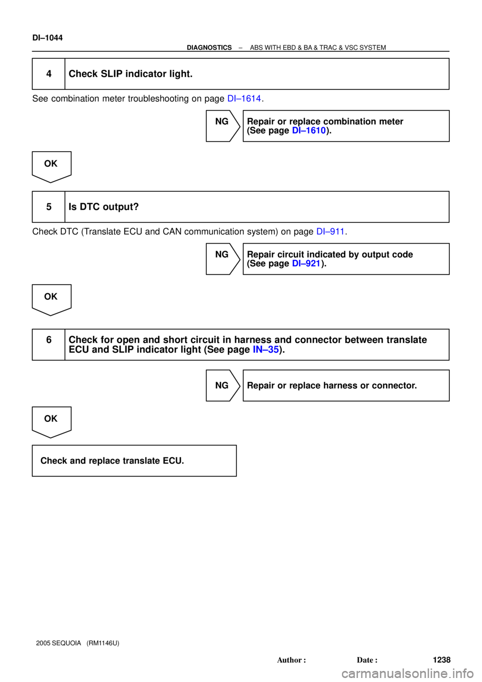
4 Check SLIP indicator light.
See combination meter troubleshooting on page DI±1614.
NG Repair or replace combination meter
(See page DI±1610).
OK
5 Is DTC output?
Check DTC (Translate ECU and CAN communication system) on page DI±911.
NG Repair circuit indicated by output code
(See page DI±921).
OK
6 Check for open and short circuit in harness and connector between translate
ECU and SLIP indicator light (See page IN±35).
NG Repair or replace harness or connector.
OK
Check and replace translate ECU.
Page 1248 of 4323
DI±1046
± DIAGNOSTICSABS WITH EBD & BA & TRAC & VSC SYSTEM
1240 Author�: Date�:
2005 SEQUOIA (RM1146U)
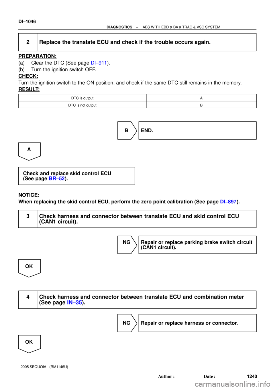
2 Replace the translate ECU and check if the trouble occurs again.
PREPARATION:
(a) Clear the DTC (See page DI±911).
(b) Turn the ignition switch OFF.
CHECK:
Turn the ignition switch to the ON position, and check if the same DTC still remains in the memory.
RESULT:
DTC is outputA
DTC is not outputB
B END.
A
Check and replace skid control ECU
(See page BR±52).
NOTICE:
When replacing the skid control ECU, perform the zero point calibration (See page DI±897).
3 Check harness and connector between translate ECU and skid control ECU
(CAN1 circuit).
NG Repair or replace parking brake switch circuit
(CAN1 circuit).
OK
4 Check harness and connector between translate ECU and combination meter
(See page IN±35).
NG Repair or replace harness or connector.
OK
Page 1249 of 4323
± DIAGNOSTICSABS WITH EBD & BA & TRAC & VSC SYSTEM
DI±1047
1241 Author�: Date�:
2005 SEQUOIA (RM1146U)
5 Check SLIP indicator light.
See combination meter troubleshooting on page DI±1614.
NG Repair combination meter assembly
(See page DI±1610).
OK
Check and replace skid control ECU
(See page BR±52).
NOTICE:
When replacing the skid control ECU, perform the zero point calibration (See page DI±897).
Page 1251 of 4323
F19780
ABS & VSC Actuator
(Skid Control ECU)
Translate ECU
CANH
CANL
IG1 VSC± VSC+
IG17
T5
11
T5
1
T56
S1
2
S1
13
S1 7
IL2
6
IL2
1
IL2 A
J38
A
J37 A
J37
8
3C8
3A L
W
B±RL
W
B±R
B±R
B±R B±R
B±R Instrument Panel J/B
4
1C
2
1C
3
1C
6
1C4
11
1H
7
1J
1
1L 1F ECU±IG
IGN1
AM1
21 AM1
AM2IG1
IG2 I18
Ignition SW
B±Y
B±R W±L
W±R
W±LB±O
W±R
W 12
56C6
Combination
Meter
VSC OFF
(4WD)
TRAC OFF
(2WD)
24
2
R±G W±R W
Engine Room J/B
1
2D1
2C AM2 F10 Fusible
Link Block
B 8
54 ALT
R±G 38
T5
26
T5
31
T5
40
T5 WT
CSW
EXI2
GND
(4WD)
Y±G
(4WD)
L±W
Y±B L±WSub J/B No.4
8
4B
7
4B7
4A8
4A16
F23
4
F23DL
PI
B
BatteryA
AJ43
J/C
IGJ18
J/C
IG A
A W±B W±B
O
OW±B
W±B 17
IL1
9
IL132
S11
S1GND1
GND2 Sub J/B No.3
4WD Control ECU J/C (*) CAN1 Circuit
(*)
(*)(*) (*)
± DIAGNOSTICSABS WITH EBD & BA & TRAC & VSC SYSTEM
DI±1049
1243 Author�: Date�:
2005 SEQUOIA (RM1146U)
WIRING DIAGRAM


IG1 13
S1 B±R 1
IL1
B±R B±R
B±R
B±R
B±R A
J38 A
J37
A
J37 1
T5 IG1 Translate ECU
8
3C8
3A J/C
4
1F
11
1H
7
1J
1
1L 4
1C
2
1C
3
1C
6
1CECU±IG
IGN1
A")


Translate ECU
CANH
CANL
IG1 VSC± VSC+
IG17
T5
11
T5
1
T56
S1
2
S1
13
S1 7
IL2
6
IL2
1
IL2 A
J38
A
J37 A
J37
8
3C8
3A L
W
B±RL
W
B±R
B±R
B±R B±R
B±R")