Page 1286 of 4323
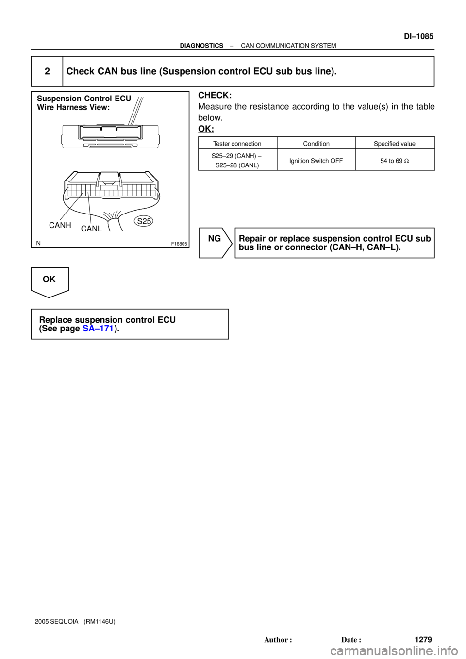
F16805
IG
S25
Suspension Control ECU
Wire Harness View:
GND
DI±1084
± DIAGNOSTICSCAN COMMUNICATION SYSTEM
1278 Author�: Date�:
2005 SEQUOIA (RM1146U)
INSPECTION PROCEDURE
1 Check wire harness (Suspension control ECU ± Battery and Suspension control
ECU ± Body ground).
PREPARATION:
Disconnect the suspension control ECU connector (S25).
CHECK:
(a) Measure the resistance according to the value(s) in the
table below.
OK:
Tester connectionConditionSpecified value
S25±22 (GND) ±
Body groundAlwaysBelow 1 W
(b) Measure the voltage according to the value(s) in the table
below.
OK:
Tester connectionConditionSpecified value
S25±10 (IG) ±
Body groundIgnition Switch ON10 to 14 V
NG Repair or replace harness or connector
(Suspension Control ECU ± Battery or Suspen-
sion Control ECU ± Body ground).
OK
Page 1287 of 4323
F16805
Suspension Control ECU
Wire Harness View:
CANH
CANLS25
± DIAGNOSTICSCAN COMMUNICATION SYSTEM
DI±1085
1279 Author�: Date�:
2005 SEQUOIA (RM1146U)
2 Check CAN bus line (Suspension control ECU sub bus line).
CHECK:
Measure the resistance according to the value(s) in the table
below.
OK:
Tester connectionConditionSpecified value
S25±29 (CANH) ±
S25±28 (CANL)Ignition Switch OFF54 to 69 W
NG Repair or replace suspension control ECU sub
bus line or connector (CAN±H, CAN±L).
OK
Replace suspension control ECU
(See page SA±171).
Page 1288 of 4323
F19701
Translate ECU
ENG+
ENG±Junction Connector
14
T5
16
T5R
W1
J55
2
J551
J53
2
J53L
W33
E5
34
E5ECM
CANH
CANL
D6 DLC3
1
J54
2
J54B
W6
14CANH
CANL DI±1086
± DIAGNOSTICSCAN COMMUNICATION SYSTEM
1280 Author�: Date�:
2005 SEQUOIA (RM1146U)
Check CAN Main Bus Line For Disconnection
CIRCUIT DESCRIPTION
The CAN main bus line and DLC3 sub bus line may have a disconnection when the resistance between ter-
minals 6 (CANH) and 14 (CANL) of the DLC3 is more than 69 W.
SymptomTrouble Area
Resistance between terminals 6 (CANH) and 14 (CANL) of
the DLC3 is more than 69 W.
�CAN main bus line
�ECM
�Translate ECU
�DLC3 sub bus line
WIRING DIAGRAM
DIDIC±01
Page 1291 of 4323
F19749
J55
R
W Junction Connector ºAº Side
(w/ Earth Terminal)
Wire Harness View:
CANL CANH
Earth Terminal
± DIAGNOSTICSCAN COMMUNICATION SYSTEM
DI±1089
1283 Author�: Date�:
2005 SEQUOIA (RM1146U)
4 Check CAN main bus line for disconnection (Translate ECU ± Junction connec-
tor).
PREPARATION:
Disconnect the translate ECU main bus line connector (J55)
from the junction connector.
NOTICE:
�Before disconnecting the connector, make a note of
where it is connected.
�Reconnect the connector to its original position.
CHECK:
Measure the resistance according to the value(s) in the table
below.
OK:
Tester connectionConditionSpecified value
J55±1 (CANH) ±
J55±2 (CANL)Ignition Switch OFF108 to 132 W
NG Go to step 7.
OK
Replace junction connector.
5 Connect the connector.
Reconnect the ECM main bus line connector (J53) to the junction connector.
NEXT
Page 1292 of 4323
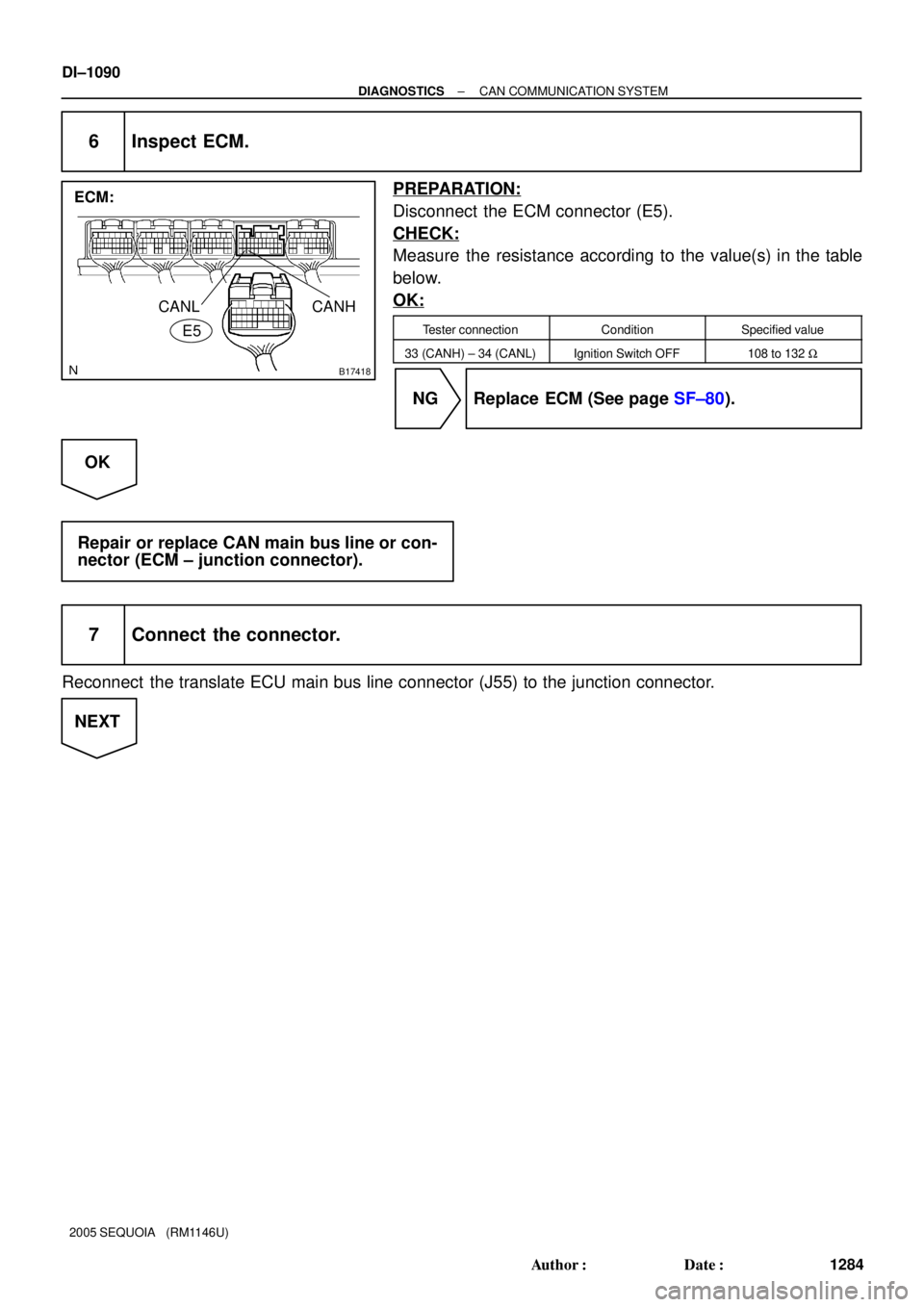
B17418
ECM:
E5
CANL CANH
DI±1090
± DIAGNOSTICSCAN COMMUNICATION SYSTEM
1284 Author�: Date�:
2005 SEQUOIA (RM1146U)
6 Inspect ECM.
PREPARATION:
Disconnect the ECM connector (E5).
CHECK:
Measure the resistance according to the value(s) in the table
below.
OK:
Tester connectionConditionSpecified value
33 (CANH) ± 34 (CANL)Ignition Switch OFF108 to 132 W
NG Replace ECM (See page SF±80).
OK
Repair or replace CAN main bus line or con-
nector (ECM ± junction connector).
7 Connect the connector.
Reconnect the translate ECU main bus line connector (J55) to the junction connector.
NEXT
Page 1293 of 4323
F19822
Translate ECU:
ENG± ENG+
± DIAGNOSTICSCAN COMMUNICATION SYSTEM
DI±1091
1285 Author�: Date�:
2005 SEQUOIA (RM1146U)
8 Inspect translate ECU.
PREPARATION:
Disconnect the translate ECU connector (T5).
CHECK:
Measure the resistance according to the value(s) in the table
below.
OK:
Tester connectionConditionSpecified value
14 (ENG+) ± 16 (ENG±)Ignition Switch OFF108 to 132 W
NG Replace translate ECU.
OK
Repair or replace CAN main bus line or con-
nector (Translate ECU ± Junction connector).
Page 1294 of 4323
F19702
ECM
CANH
CANL
ENG+
ENG± CANH
CANL
CANH
CANL D6 DLC3
Translate ECU
Suspension Control ECU33
E5
34
E5L
W1
J53
2
J53Junction Connector
1
J54
2
J54 B
W 6
14
14
T5
16
T51
J55
2
J55 R
W
29
S25
28
S25G
W (*1)
(*1)1
J56
2
J56
*1: w/ Air Suspension System DI±1092
± DIAGNOSTICSCAN COMMUNICATION SYSTEM
1286 Author�: Date�:
2005 SEQUOIA (RM1146U)
Check CAN Bus Lines For Short Circuit
CIRCUIT DESCRIPTION
There may be a short circuit between the CAN bus lines when the resistance between terminals 6 (CANH)
and 14 (CANL) of the DLC3 is below 54 W.
SymptomTrouble Area
Resistance between terminals 6 (CANH) and 14 (CANL) of
the DLC3 is below 54 W.
�Short between CAN bus lines
�Translate ECU
�Suspension control ECU
�ECM
�Junction connector
WIRING DIAGRAM
DIDID±01
Page 1297 of 4323
F19749
Junction Connector ºAº Side
(w/ Earth Terminal)
Wire Harness View:
J55
W R
Earth Terminal
12345678
9 10111213141516
F19737
DLC3:
D6CANH
CANL
± DIAGNOSTICSCAN COMMUNICATION SYSTEM
DI±1095
1289 Author�: Date�:
2005 SEQUOIA (RM1146U)
5 Check CAN bus lines for short circuit (Translate ECU main bus line).
PREPARATION:
Disconnect the translate ECU main bus line connector (J55)
from the junction connector.
NOTICE:
�Before disconnecting the connector, make note of
where it is connected.
�Reconnect the connector to its original position.
CHECK:
Measure the resistance according to the value(s) in the table
below.
OK:
Tester connectionConditionSpecified value
D6±6 (CANH) ±
D6±14 (CANL)Ignition Switch OFF108 to 132 W
OK Go to step 10.
NG
6 Connect the connector.
Reconnect the translate ECU main bus line connector (J55) to the junction connector.
NEXT


Wire Harness View:
J55
W R
Earth Terminal
12345678
9 10111213141516
F19737
DLC3:
D6CANH
CANL
± DIAGNOSTICSCAN COMMUNICATION SYSTEM
DI±1095
1")