Page 3424 of 4323

NAVIGATION SYSTEM
SymptomSuspect AreaSee page
Navigation system abnormal operation.See DIAGNOSIS SYSTEMDI±2172
R")
BE±12
± BODY ELECTRICALTROUBLESHOOTING
3416 Author�: Date�:
2005 SEQUOIA (RM1146U)
NAVIGATION SYSTEM
SymptomSuspect AreaSee page
Navigation system abnormal operation.See DIAGNOSIS SYSTEMDI±2172
REAR SEAT ENTERTAINMENT SYSTEM
SymptomSuspect AreaSee page
Rear seat entertainment system abnormal operation.See DIAGNOSIS SYSTEMDI±2083
REAR SEAT AUDIO SYSTEM
SymptomSuspect AreaSee page
Rear seat audio system abnormal operation.See DIAGNOSIS SYSTEMDI±2048
CLOCK SYSTEM
SymptomSuspect AreaSee page
Clock does not operate.TROUBLESHOOTING NO.1BE±127
Clock loses or gains time.TROUBLESHOOTING NO.2BE±127
GARAGE DOOR OPENER SYSTEM
SymptomSuspect AreaSee page
The equipment of which code has been registered does not oper-
ate.1. Garage Door Opener Switch
2. Wire Harness
3. *BE±134
±
±
LED does not come on. (Even though either switch is pressed.)1. Garage Door Opener Switch
2. Wire HarnessBE±134
±
LED does not come on. (Only one switch is pressed.)Garage Door Opener SwitchBE±134
* As the GARAGE DOOR OPENER on the vehicle side seems to be normal, check the OPENER on the
equipment side, of which code has been registered.
ENGINE IMMOBILISER SYSTEM
SymptomSuspect AreaSee page
Engine immobilizer system does not operate.See DIAGNOSIS SYSTEMBE±143
HORN SYSTEM
This system uses the multiplex communication system, so check diagnosis system of the multiplex commu-
nication system before you proceed with troubleshooting.
SymptomSuspect AreaSee page
Horn system does not operate.
1. HORN Fuse
2. HORN Relay Circuit
3. Horn Switch Circuit
4. Horn
5. Body ECUBE±14
BE±145
BE±145
BE±145
±
Horn blow all the time.
1. HORN Relay Circuit
2. Horn Switch Circuit
3. Body ECUBE±145
BE±145
±
One horn operates but the other horn does not operate.1. Horn
2. Wire HarnessBE±145
±
Page 3429 of 4323

I28399
Fusible Link Block:
Relays: Fuses:
5. RR HEATER Fuse 30 A
A. C/OPN Relay
B. HEAD Relay
C. EFI Relay
D. FUEL PUMP Relay
E. DEFOG Relay
F. HORN Relay
Engine Room J/B6. R/B Fuse 30 A
7. A/PUMP Fuse 50 A
8. ABS Fuse 60 A
9. ALT Fuse 140 A
10. CDS FAN Fuse 25 A
11. Spare Fuse 15 A
12. Spare Fuse 20 A
13. Spare Fuse 30 A
14. Main Fuse 40 A
15. DOOR No. 2 Fuse 30 A
16. *2 H±LP RH Fuse 15 A
17. EFI No. 1 Fuse 20 A
18. ETCS Fuse 10 A19. *1.DRL Fuse 15 A
*2.H±LP LH Fuse 15 A
20. ALT±S Fuse 7.5 A
21. TOWING Fuse 30 A
22. ST Fuse 30 A
23. RAD No. 3 Fuse 30 A
24. TURN±HAZ Fuse 20 A
25. AM2 Fuse 25 A
26. EFI No. 2 Fuse 10 A
27. SHORT±PIN
28. HORN Fuse 10 A
29. MIR HTR Fuse 15 A
30. ECU±B Fuse 7.5 A
31. DOME Fuse 10 A
32. RAD No. 1 Fuse 20 A
*1 w/ Daytime Running Light
*2 w/o Daytime Running Light 15
16 17 18
19 20 21
262728
2930
A
B
C
D
EF 1
234
5
6789
10
22 2324 25
31
32
11
12
13141. TOWING R/B Fuse 50 A
2. AIR SUS Fuse 50 A
3. HEATER Fuse 50 A
4. DEFOG Fuse 40 A
± BODY ELECTRICALPOWER SOURCE
BE±17
3421 Author�: Date�:
2005 SEQUOIA (RM1146U)
Page 3494 of 4323

THEFT DETERRENT SYSTEM
ON±VEHICLE INSPECTION
1. OUTLINE OF THEFT DETERRENT SYSTEM
When the thef")
BE2ML±01
BE±82
± BODY ELECTRICALTHEFT DETERRENT SYSTEM
3486 Author�: Date�:
2005 SEQUOIA (RM1146U)
THEFT DETERRENT SYSTEM
ON±VEHICLE INSPECTION
1. OUTLINE OF THEFT DETERRENT SYSTEM
When the theft deterrent system detects any theft, it informs
people around by flashing lights and sound.
All initial settings are performed in active mode. It can be
switched to passive mode by using the hand±held tester. (See
step 3. CHANGING METHOD OF PASSIVE MODE.)
HINT:
There are 4 conditions in this system: disarmed state, arming
preparation, armed state and alarm sounding.
(1) Disarmed state
�Alarm function does not operate.
�Theft deterrent function is not performed.
(2) Arming preparation
�Time until transferring to armed state.
�Theft deterrent function is not performed.
(3) Armed state
Theft deterrent function is ready.
(4) Alarm sounding:
When the system detects a theft, it informs people
around the vehicle using light and sound.
Refer to the table below for alarming method or
time.
Horn
Security horn
Alarm methodHeadlightAlarm method
Taillight
Interior light
Alarm time60 seconds
Alarm outputContinuous 0.4 secs. (ON)
0.4 secs. (OFF)
HINT:
Alarm output for the hazard is the same as the one for the haz-
ard on the vehicle.
If any of the doors is unlocked not by the key or wireless remote
control in the armed state, a force lock signal will be output.
Page 3495 of 4323

Disarmed state
Perform any of the following and the system will go on to ºArming preparationº:
� With all the doors, the engine hood and the back door closed, lock all doors with the key.
� With all the doors, the engine hood and the back door closed, lock all doors by the
wireless remote control.
� With all the doors, engine hood and back door locked, open and close any of the doors, the
engine hood or the back door, then close and lock all doors, the engine hood and the back door.
Arming preparation
Perform the following and the system will
go on to ºArmed stateº:
� Let 30 seconds elapse with all the doors,
engine hood and the back door closed and
locked.
Perform any of the following and the system
will return to ºDisarmed stateº:
� Open any of the doors, the engine hood or
the back door .
� Unlock any of the doors or the back door.
� Put the key in the key cylinder.
� Reconnect the battery.
Armed state
Perform any of the following and the system
will return to ºDisarmed stateº:
� Unlock any of the doors or the back door by
the wireless remote control.
� Unlock any of the doors or the back door with
the key.
� Put the key in the key cylinder and turn it ON.
Perform any of the following and the system
will go on to ºAlarm soundingº:
� Open any of the doors or the back door.
� Unlock any of the doors or the back door in
any way other than with a key or by the wireless
remote control.
� Open the engine hood.
� Reconnect the battery.
� When input from the optional glass break sensor
is detected (Dealer option).(Key not inserted in key cylinder.)
Alarm sounding
The vehicle's horn and security horn will sound,
and the hazard, interior, tail and head lights come
on for 60 seconds.
After the alarm has stopped, the system will
return to ºArmed stateº. Perform any of the following and the system
will return to ºDisarmed stateº:
� Unlock any of the doors and the back door by
the wireless remote control.
� Unlock any of the doors or the back door with
the key.
� Put the key in the key cylinder and turn it ON.
± BODY ELECTRICALTHEFT DETERRENT SYSTEM
BE±83
3487 Author�: Date�:
2005 SEQUOIA (RM1146U)
2. ACTIVE ARMING MODE
Page 3503 of 4323
BE0CE±10
I28416
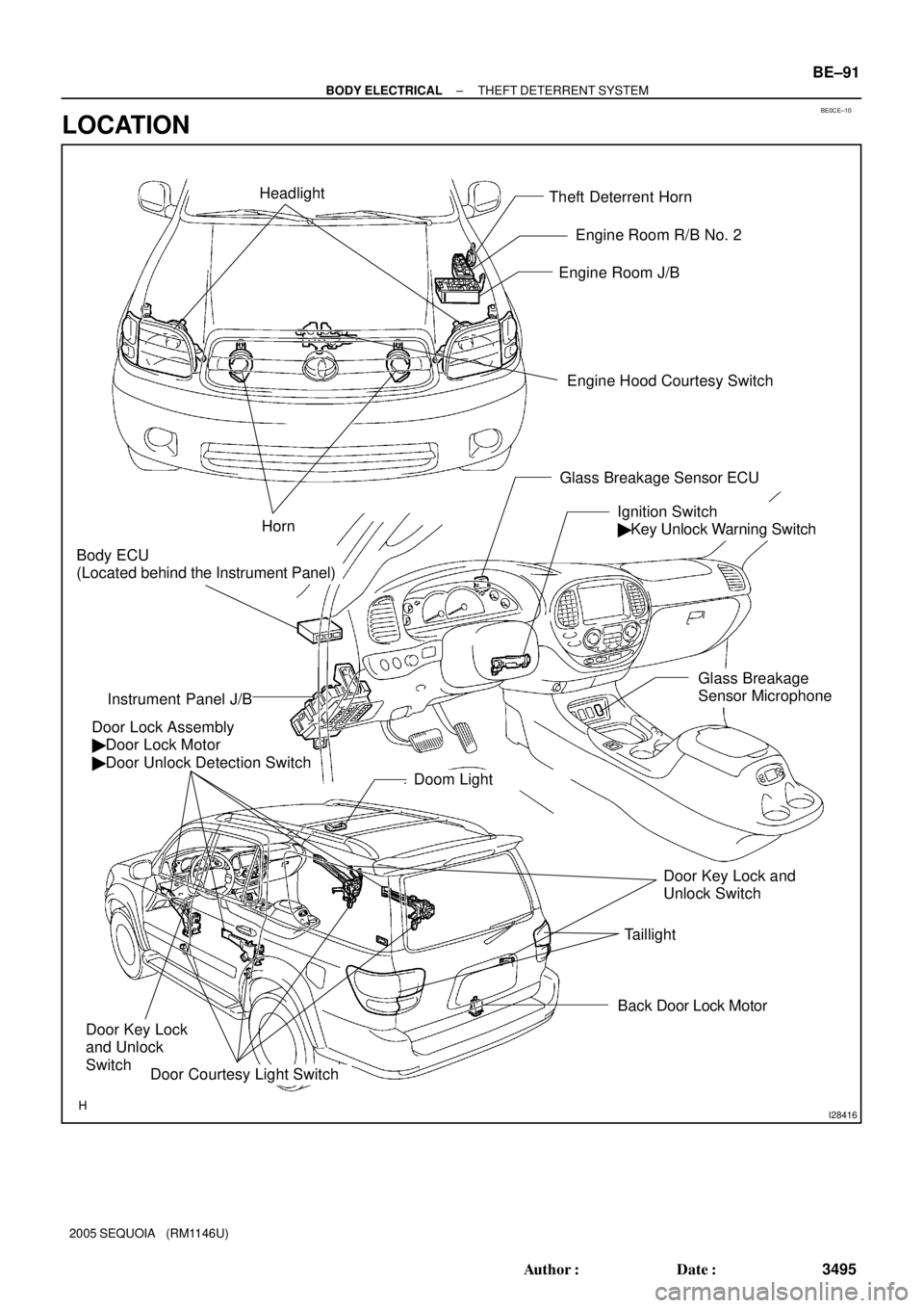
Theft Deterrent Horn
Engine Hood Courtesy Switch Engine Room J/B
Door Lock Assembly
� Door Lock Motor
� Door Unlock Detection Switch
Ignition Switch
� Key Unlock Warning Switch
Instrument Panel J/B
Door Courtesy Light Switch
Horn
Back Door Lock Motor
Door Key Lock
and Unlock
Switch
Door Key Lock and
Unlock Switch Headlight
Doom Light
Taillight
Body ECU
(Located behind the Instrument Panel)
Engine Room R/B No. 2
Glass Breakage Sensor ECU
Glass Breakage
Sensor Microphone
± BODY ELECTRICALTHEFT DETERRENT SYSTEM
BE±91
3495 Author�: Date�:
2005 SEQUOIA (RM1146U)
LOCATION
Page 3504 of 4323
I04146
BE1W8±05
I04148
ON OFF BE±92
± BODY ELECTRICALTHEFT DETERRENT SYSTEM
3496 Author�: Date�:
2005 SEQUOIA (RM1146U)
INSPECTION
1. INSPECT THEFT DETERRENT HORN OPERATION
Connect the positive (+) lead from the battery to terminal 1 and
negative (±) lead to the theft deterrent horn body, and check
that the theft deterrent horn blows.
If operation is not as specified, replace the horn.
2. INSPECT ENGINE HOOD COURTESY SWITCH CON-
TINUITY
Switch positionTester connectionSpecified condition
CLOSE (OFF)±No continuity
OPEN (ON)1 ± 2Continuity
If continuity is not as specified, replace the switch.
3. INSPECT ENGINE HOOD COURTESY SWITCH CIR-
CUIT (See page DI±1725)
Page 3556 of 4323
BE0FY±32
I28423
Horn
Horn Switch
Engine Room J/B
� HORN Relay
� HORN Fuse
BE±144
± BODY ELECTRICALHORN SYSTEM
3548 Author�: Date�:
2005 SEQUOIA (RM1146U)
HORN SYSTEM
LOCATION
Page 3557 of 4323

INSPECTION
1. INSPECT HORN SWITCH
(a) Disconnect the negative (±) terminal from the")
BE0FZ±25
I24377
I24378
I04197
± BODY ELECTRICALHORN SYSTEM
BE±145
3549 Author�: Date�:
2005 SEQUOIA (RM1146U)
INSPECTION
1. INSPECT HORN SWITCH
(a) Disconnect the negative (±) terminal from the battery.
(b) Remove the left and right covers from the steering wheel.
(c) Using a torx socket wrench, loosen the 2 bolts.
(d) Pull up the horn pad and place it on the steering column,
as shown.
HINT:
Do not disconnect the connector from the horn pad.
(e) Disconnect the connector from the slip ring.
(f) Check that no continuity exists between terminal 6 of the
connector and body ground.
(g) Check that continuity exists between terminal 6 of the
connector and body ground when the horn contact plate
is pressed against the steering spoke assembly.
If continuity is not as specified, repair or replace the steering
wheel or wire harness as necessary.
(h) Install the horn pad in place and using a torx socket
wrench, torque the 2 bolts.
Torque:
7.1 N´m (72 kgf´cm, 62 in.´lbf)
(i) Install the left and right covers.
(j) Connect the negative (±) terminal to the battery.
2. INSPECT HORN OPERATION
Connect the positive (+) lead from the battery to the terminal
and negative (±) lead to the horn body and check that the horn
blows.
If operation is not as specified, replace the horn.
3. INSPECT HORN SWITCH CIRCUIT
(See page DI±1764)