Page 1900 of 4323

� H±LP LH Fuse (*2)
� DRL Fuse (*1)
Rear Washer Motor
Horn
Headlight
Rear washer switch
Igni")
DI94R±07
I28393
Hood Courtesy Switch Engine Room J/B
� ECU±B Fuse
� Door No. 2 Fuse
� H±LP RH Fuse (*2)
� H±LP LH Fuse (*2)
� DRL Fuse (*1)
Rear Washer Motor
Horn
Headlight
Rear washer switch
Ignition Switch
� Key Unlock Switch
DLC3 Body ECU
Instrument Panel J/B
� ECU±IG Fuse
� RAD No. 2 Fuse
� FOG Fuse
� FOG LIGHT Relay
� POWER MAIN Relay
� WSH Fuse
� STOP Fuse
� TAILLIGHT Relay Back Door Power
Window SwitchTheft Horn
Engine Room R/B
No.2
� DIMMER Relay
� DRL No. 4 Relay
� H±LP RH Fuse (*1)
� H±LP LH Fuse (*1)
� H±LP RL Fuse (*1)
� H±LP LL Fuse (*1)
Fog Light
Wireless Door
Control Receiver Wireless Door Lock Buzzer
Combination Meter Memory Seat Switch
(*1): w/ Daytime Running Light
(*2): w/o Daytime Running Light (Located behind
the instrument panel)
(Located behind
the heater control panel)
� DOME Fuse
� HEAD Relay
� HORN Relay
� DOME Fuse
Automatic Light Control Sensor
Stop Light Switch
Remote Control Mirror SwitchGlass Breakage
Sensor Microphone Glass Breakage
Sensor ECU
Combination Switch
� Light Control Switch
� Headlight Dimmer Switch
� Fog Light Switch DI±1698
± DIAGNOSTICSBODY CONTROL SYSTEM
1892 Author�: Date�:
2005 SEQUOIA (RM1146U)
PARTS LOCATION
Page 1901 of 4323
I28394
Parking Brake Switch
Door Lock Motor
Rear Power
Window Motor Courtesy Light
Switch
Courtesy LightRear Courtesy Light Switch Horn Switch
Stop Light Rear Room Light Front Map Light
Courtesy Light Rear Courtesy
Light Switch Door Lock Motor
Rear Power
Window MotorRear Window Control
Switch RH Door Lock Motor
Power Window Switch
� Passenger Door ECU
� Door Lock Control Switch
� Power Window Switch
Stop Light
Power Window
Master Switch
� Driver
Door ECU
� Door Lock
Control Switch
� Power
Window Switch
� Window Lock
Switch
Door Lock Motor
Rear Window
Control Switch LH
± DIAGNOSTICSBODY CONTROL SYSTEM
DI±1699
1893 Author�: Date�:
2005 SEQUOIA (RM1146U)
Page 1902 of 4323
DI94S±08
DI±1700
± DIAGNOSTICSBODY CONTROL SYSTEM
1894 Author�: Date�:
2005 SEQUOIA (RM1146U)
CIRCUIT INSPECTION
Power source circuit
CIRCUIT DESCRIPTION
This circuit provides power to operate the body ECU.
BDR terminal: Power source for door lock motor
S+B terminal: Power source for security horn
ACC terminal: Power source for accessory
BECU terminal: Power source for backing up body ECU
IG terminal: Power source for starting body ECU
WIG terminal: Power source for washer motor
Page 1936 of 4323
I18735
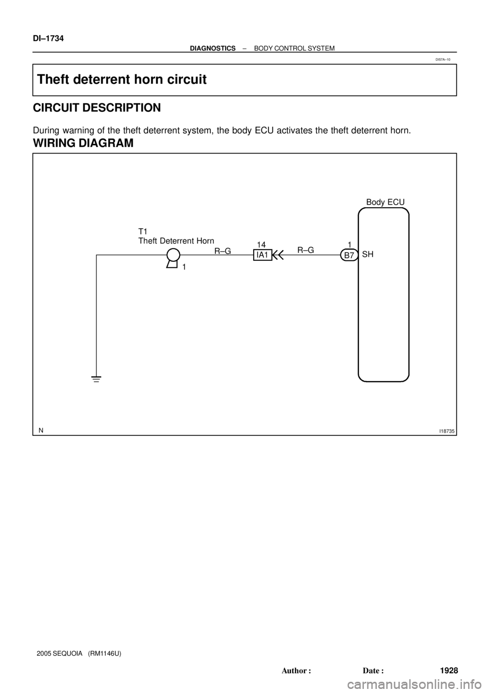
1Body ECU
T1
Theft Deterrent Horn
IA114
R±G
B71
SH R±G DI±1734
± DIAGNOSTICSBODY CONTROL SYSTEM
1928 Author�: Date�:
2005 SEQUOIA (RM1146U)
Theft deterrent horn circuit
CIRCUIT DESCRIPTION
During warning of the theft deterrent system, the body ECU activates the theft deterrent horn.
WIRING DIAGRAM
DI57A±10
Page 1937 of 4323
± DIAGNOSTICSBODY CONTROL SYSTEM
DI±1735
1929 Author�: Date�:
2005 SEQUOIA (RM1146U)
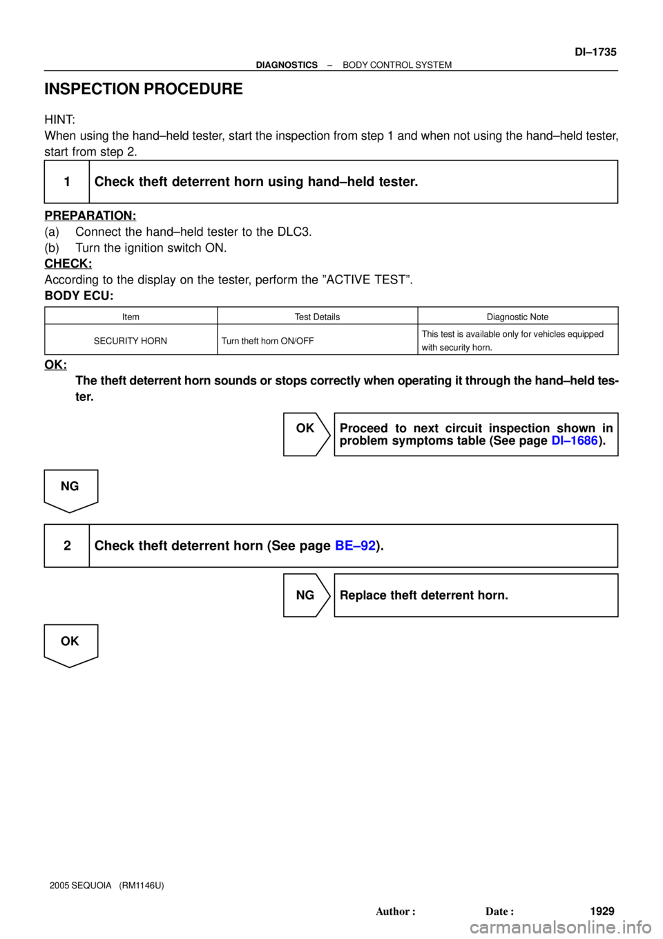
INSPECTION PROCEDURE
HINT:
When using the hand±held tester, start the inspection from step 1 and when not using the hand±held tester,
start from step 2.
1 Check theft deterrent horn using hand±held tester.
PREPARATION:
(a) Connect the hand±held tester to the DLC3.
(b) Turn the ignition switch ON.
CHECK:
According to the display on the tester, perform the ºACTIVE TESTº.
BODY ECU:
ItemTest DetailsDiagnostic Note
SECURITY HORNTurn theft horn ON/OFFThis test is available only for vehicles equipped
with security horn.
OK:
The theft deterrent horn sounds or stops correctly when operating it through the hand±held tes-
ter.
OK Proceed to next circuit inspection shown in
problem symptoms table (See page DI±1686).
NG
2 Check theft deterrent horn (See page BE±92).
NG Replace theft deterrent horn.
OK
Page 1938 of 4323
DI±1736
± DIAGNOSTICSBODY CONTROL SYSTEM
1930 Author�: Date�:
2005 SEQUOIA (RM1146U)
3 Check wire harness and connector between theft deterrent horn and body ECU,
theft deterrent horn and body ground (See page IN±35).
NG Repair or replace wire harness or connector.
OK
Proceed to next circuit inspection shown in
problem symptoms table
(See page DI±1686).
Page 1966 of 4323
I24147
B7
HORN HORN Relay
2
1Body ECU
1
2D18
HR
HORN
B5 B±Y
6 C9
Horn SW
B54 F10
FL Block H8
Horn (low)
1
1 B B8
2H
7
2F5
3W±R W±R19
IA1
26
Battery H7
Horn (high)Engine Room J/B
B DI±1764
± DIAGNOSTICSBODY CONTROL SYSTEM
1958 Author�: Date�:
2005 SEQUOIA (RM1146U)
Horn circuit
CIRCUIT DESCRIPTION
The vehicle horn sounds when the horn switch is pressed. It also sounds as an alarm for the theft deterrent
system when the body ECU detects any alert condition.
WIRING DIAGRAM
DI94T±08
Page 1967 of 4323
± DIAGNOSTICSBODY CONTROL SYSTEM
DI±1765
1959 Author�: Date�:
2005 SEQUOIA (RM1146U)
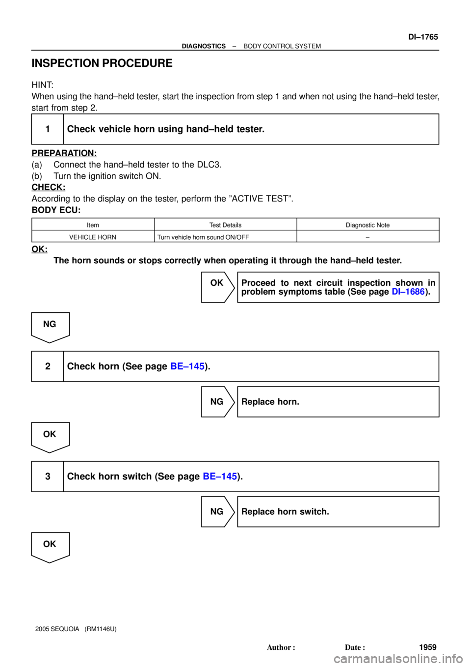
INSPECTION PROCEDURE
HINT:
When using the hand±held tester, start the inspection from step 1 and when not using the hand±held tester,
start from step 2.
1 Check vehicle horn using hand±held tester.
PREPARATION:
(a) Connect the hand±held tester to the DLC3.
(b) Turn the ignition switch ON.
CHECK:
According to the display on the tester, perform the ºACTIVE TESTº.
BODY ECU:
ItemTest DetailsDiagnostic Note
VEHICLE HORNTurn vehicle horn sound ON/OFF±
OK:
The horn sounds or stops correctly when operating it through the hand±held tester.
OK Proceed to next circuit inspection shown in
problem symptoms table (See page DI±1686).
NG
2 Check horn (See page BE±145).
NG Replace horn.
OK
3 Check horn switch (See page BE±145).
NG Replace horn switch.
OK


1
1 B B8
2H
7
2F5
3W±R W±R19
IA1
26
Battery H7
Horn (high)Engine Room J/B
B DI±1764
± DIAG")