Page 1149 of 4323
F19771
F10
Fusible Link BlockInstrument Panel J/BI18
Ignition SWABS & VSC Actuator
(Skid Control ECU)
ALT
B
58W1
1L
1AM1
6
1C
2
4
1F4
1C Sub J/B No.3
8
3C8
3AW±L
12
ECU±IGAM1IG1
B±Y B±R
B±R
B±RB±R
B±R B±RA
J37A
J38
A
J37A
J371
IL113
S1 IG1
1 S7
Steering Angel Sensor
IG
TRIG
SS1±
SS1+
BAT
ESS10
11
3
9
B
BatteryW±L
Y
OL
WL
W Translate ECU
20
T5
19
T5
18
T5
40
T5
1 T5
7
T5
11
T5 TRIG
SS1±
SS1+
GNDIG1
VSC+
VSC±IL2
6
IL26
S1
2
S1
O
P±L P±L
P±L
W±B7
IL2 12
IL1 17
IL19W±B
W±B
W±B41
S1
S1
32
S1CANH
CANL
+BO
GND1
GND2 O
O
O A
A
AA
A
J43
J/CJ18
J/C
IG
IG1 J/C
2
± DIAGNOSTICSABS WITH EBD & BA & TRAC & VSC SYSTEM
DI±947
1141 Author�: Date�:
2005 SEQUOIA (RM1146U)
WIRING DIAGRAM
Page 1151 of 4323
± DIAGNOSTICSABS WITH EBD & BA & TRAC & VSC SYSTEM
DI±949
1143 Author�: Date�:
2005 SEQUOIA (RM1146U)
3 Check for open and short circuit in harness and connector between steering
angle sensor and translate ECU (See page IN±35).
NG Repair or replace harness or connector.
OK
4 Check for open and short circuit in harness and connector between skid control
ECU and translate ECU (CAN1 circuit).
NG Repair or replace harness or connector
(CAN1 circuit).
OK
5 Is DTC still output?
Check DTC on page DI±911.
NO No problem.
YES
Page 1152 of 4323

6 Replace the skid control ECU and check if trouble occurs again.
PREPARATION:
(a) Clear the D")
DI±950
± DIAGNOSTICSABS WITH EBD & BA & TRAC & VSC SYSTEM
1144 Author�: Date�:
2005 SEQUOIA (RM1146U)
6 Replace the skid control ECU and check if trouble occurs again.
PREPARATION:
(a) Clear the DTC.
(b) Turn the ignition switch OFF.
CHECK:
Check if the same DTC still remains in the memory.
RESULT:
DTC is outputA
DTC is not outputB
B END.
A
Replace steering angle sensor.
NOTICE:
�When replacing the skid control ECU, perform the zero point calibration (See page DI±897).
�If the steering angle sensor has been replaced, drive the vehicle straight ahead at a speed of
6.5 mph (10.5 km/h) or more to calibrate the steering angle sensor.
7 Check DTC once more (See page DI±911).
PREPARATION:
(a) Clear the DTC.
(b) Turn the ignition switch OFF.
CHECK:
Check if the same DTC still remains in the memory.
RESULT:
DTC is outputA
DTC is not outputB
B END.
A
Replace skid control ECU with actuator
(See page BR±52).
NOTICE:
When replacing the skid control ECU, perform the zero point calibration (See page DI±897).
Page 1153 of 4323

SensorABS & VSC Actuator
(Skid Control ECU)
(Shielded)S1
S1
(Shielded) VYS
YAW 1
GYAWR
B
W
SS2
S1 24 IL1
IL1
IL1
IL143
1")
F16952
VYS
SS1
GYAW S1
23 R
B
W
IM BRIL112
1911
3
12 Y1
Yaw Rate (Deceleration)
SensorABS & VSC Actuator
(Skid Control ECU)
(Shielded)S1
S1
(Shielded) VYS
YAW 1
GYAWR
B
W
SS2
S1 24 IL1
IL1
IL1
IL143
11
10 G
G YAW 2
5(*)
(*)
(*) CAN2 Circuit(*)
(*)
± DIAGNOSTICSABS WITH EBD & BA & TRAC & VSC SYSTEM
DI±951
1145 Author�: Date�:
2005 SEQUOIA (RM1146U)
DTCC1232 / 32, C1244 / 44Deceleration Sensor Circuit
CIRCUIT DESCRIPTION
The skid control ECU receives signals from the yaw rate sensor (deceleration sensor) via the CAN2 commu-
nication system.
The yaw rate sensor has a built±in deceleration sensor.
This sensor detects deceleration on the vehicle. The sensor signal is used in ABS & BA & TRAC & VSC
control.
DTC No.DTC Detecting ConditionTrouble Area
C1232 / 32When the lateral deceleration output becomes 4.8 V or
more or 0.2 V or less per 0.5 second.�Yaw rate (Deceleration) sensor
�Yaw rate (Deceleration) sensor circuit
C1244 / 44
When any of the following conditions are detected:
1. When the supplied voltage to the yaw rate & decelera-
tion sensor becomes 18 V or more or 6.5 V or less.
2. When the longitudinal deceleration output becomes 4.8
V or more or 0.2 V or less per 0.5 second.
�Yaw rate (Deceleration) sensor
�Yaw rate (Deceleration) sensor circuit
WIRING DIAGRAM
DIDM8±01
Page 1155 of 4323
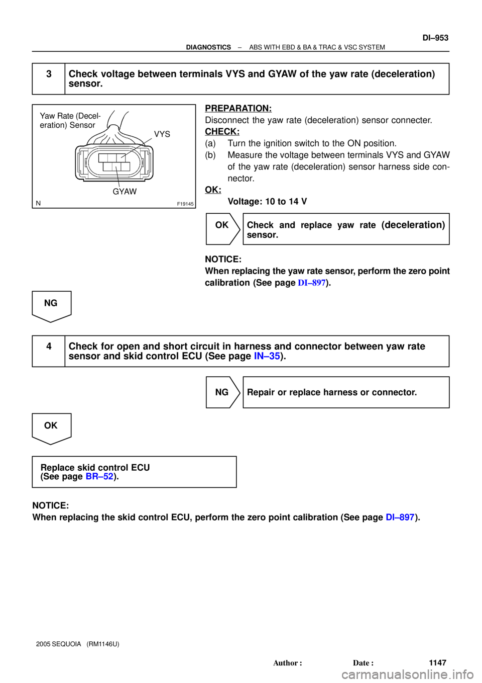
F19145
Yaw Rate (Decel-
eration) Sensor
VYS
GYAW
± DIAGNOSTICSABS WITH EBD & BA & TRAC & VSC SYSTEM
DI±953
1147 Author�: Date�:
2005 SEQUOIA (RM1146U)
3 Check voltage between terminals VYS and GYAW of the yaw rate (deceleration)
sensor.
PREPARATION:
Disconnect the yaw rate (deceleration) sensor connecter.
CHECK:
(a) Turn the ignition switch to the ON position.
(b) Measure the voltage between terminals VYS and GYAW
of the yaw rate (deceleration) sensor harness side con-
nector.
OK:
Voltage: 10 to 14 V
OK Check and replace yaw rate
(deceleration)
sensor.
NOTICE:
When replacing the yaw rate sensor, perform the zero point
calibration (See page DI±897).
NG
4 Check for open and short circuit in harness and connector between yaw rate
sensor and skid control ECU (See page IN±35).
NG Repair or replace harness or connector.
OK
Replace skid control ECU
(See page BR±52).
NOTICE:
When replacing the skid control ECU, perform the zero point calibration (See page DI±897).
Page 1156 of 4323
S1
S1
(Shielded) VYS
YAW 1
GYAWR
B
W
SS2
S1 24 IL1
IL1
IL1
IL14 3
11
10 G
G YAW 2
5ABS & VSC Actuator
(Skid Control ECU) Y1
Yaw Rate (Dec")
F16952
VYS
SS1
GYAW S1
23 R
B
W
IM BRIL112
1911
3
12
(Shielded)S1
S1
(Shielded) VYS
YAW 1
GYAWR
B
W
SS2
S1 24 IL1
IL1
IL1
IL14 3
11
10 G
G YAW 2
5ABS & VSC Actuator
(Skid Control ECU) Y1
Yaw Rate (Deceleration)
Sensor
(*)
(*)
(*) CAN2 Circuit(*)
(*) DI±954
± DIAGNOSTICSABS WITH EBD & BA & TRAC & VSC SYSTEM
1148 Author�: Date�:
2005 SEQUOIA (RM1146U)
DTC C1234 / 34 Malfunction in Yaw Rate Sensor
CIRCUIT DESCRIPTION
Yaw rate sensor detects the vehicle's sideslip and sends signals to the skid control ECU.
DTC No.DTC Detecting ConditionTrouble Area
C1234 / 34
When any of the following conditions are detected:
1. Power output of 4.65 V or more or 0.25 or less continues
for 0.1 sec. or more.
�Yaw rate (deceleration) sensorC1234 / 34for 0.1 sec. or more.
2. Difference between the actual output value of the yaw
rate sensor and the output value calculated from the
other sensor's continues to be large.�Ya w rate (deceleration) sensor
�Yaw rate (deceleration) sensor circuit
WIRING DIAGRAM
DIDM9±01
Page 1158 of 4323
F19145
Yaw Rate Sensor
VYS
GYAW
DI±956
± DIAGNOSTICSABS WITH EBD & BA & TRAC & VSC SYSTEM
1150 Author�: Date�:
2005 SEQUOIA (RM1146U)
3 Check voltage between terminal VYS and GYAW of the yaw rate sensor.
PREPARATION:
Disconnect the yaw rate sensor connecter.
CHECK:
(a) Turn the ignition switch to the ON position.
(b) Measure the voltage between terminal VYS and GYAW
of the yaw rate sensor harness side connector.
OK:
Voltage: 10 to 14 V
OK Check and replace yaw rate sensor.
NOTICE:
When replacing the yaw rate sensor, perform the zero point
calibration (See page DI±897).
NG
4 Check for open and short circuit in harness and connector between yaw rate
sensor and skid control ECU (See page IN±35).
NG Repair or replace harness or connector.
OK
Replace skid control ECU
(See page BR±52).
NOTICE:
When replacing the skid control ECU, perform the zero point calibration (See page DI±897).
Page 1159 of 4323
F19782
Battery16
S1+BS
GND1
GND2
+BM S1
S1 S1 47
1
32 B±R
B±R
W±B
W±B W±B W±B 5 BF10
Fusible Link BlockABS & VSC Actuator
(Skid Control ECU)
IG J18
J/C
A A3
ABS
Motor Relay
Pump
Motor IL117
IL19
± DIAGNOSTICSABS WITH EBD & BA & TRAC & VSC SYSTEM
DI±957
1151 Author�: Date�:
2005 SEQUOIA (RM1146U)
DTC C1241 / 41 Power Source Circuit
CIRCUIT DESCRIPTION
If there is a problem with the skid control ECU power supply circuit, the skid control ECU outputs DTC and
prohibits operation under the fail safe function.
DTC No.DTC Detecting ConditionTrouble Area
C1241 / 41
When any of the following conditions are detected:
1. ECU terminal +BM/+BS voltage is too low for a fixed
time during driving.
2. ECU terminal +BM/+BS voltage is too high for a fixed
time while ignition switch is ON.�Battery
�Charging system
�Power source circuit (+BM, +BS)
�Skid control ECU
WIRING DIAGRAM
DIDMA±01

ALT
B
58W1
1L
1AM1
6
1C
2
4
1F4
1C Sub J/B No.3
8
3C8
3AW±L
12
ECU±IGAM1IG1
B±Y B±R
B±R
B±")


IG J18
J/C
A A3
ABS
Motor Relay
Pump
Motor IL117
IL19")