Page 1188 of 4323
DI±986
± DIAGNOSTICSABS WITH EBD & BA & TRAC & VSC SYSTEM
1180 Author�: Date�:
2005 SEQUOIA (RM1146U)
DTC C1361 / 62 Abnormal Battery Voltage of VSC Sen-
sor
CIRCUIT DESCRIPTION
Supplies power to the VSC sensors (yaw rate and master cylinder pressure sensors) through terminal IG1.
DTC No.DTC Detecting ConditionTrouble Area
C1361/62Voltage from VSC sensor system to ECU is abnormal.
�Battery
�Charging system
�Power source circuit
�Skid control ECU
�Yaw rate (deceleration) sensor
�Master cylinder pressure sensor
DIDME±01
Page 1189 of 4323
M2
Master Cylinder
Pressure Sensor No.1
F19776
ABS & VSC Actuator
(Skid Control ECU)
IG1 13
S1 B±R 1
IL1 B±R B±R B±RA
J38 J/C
A
J37 8
3C 8
3ASub J/B No.3
B±RInstrument Panel J/B
4
1F
1
1L4
1C
6
1C ECU±IG
AM1
WB±Y
W±L
B±Y W±LI18
Ignition SW
12
AM1 IG1Y1
Yaw Rate (Deceleration)
Sensor
(Shield)G 5 3R
R12 11
S1
24
S1VYS
GYAW
E1 VYS
GYAW
BR
(Shield)
B
R
W30
S1
28
S1
29
S1VCM
PMC VCM
PMC
E1
BR
A
A
A
BRJ28
J/C Instrument Panel J/B
9
1F12
1KW±B
W±B
BR
J8
J/C
IE IG(Shield)
1 2 3
B
R
W26
S1
25
S1
27
S1VCM2
PMC2
E2 VCM2
PMC2
E2
1
S1
32
S1GND1
GND2 W±B
W±B W±B
W±B17
IL1
9
IL1 A
A J18
J/C 8
5ALTF10
Fusible
Link
Block12
B
Battery
IMA
J18
J/CM3
Master Cylinder
Pressure Sensor No.2G 11
10 IL1
IL1
IL1
1 2
3
± DIAGNOSTICSABS WITH EBD & BA & TRAC & VSC SYSTEM
DI±987
1181 Author�: Date�:
2005 SEQUOIA (RM1146U)
WIRING DIAGRAM
Page 1191 of 4323
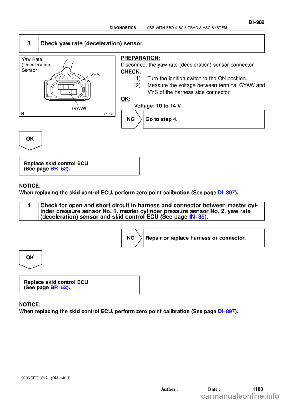
F19145
Yaw Rate
(Deceleration)
Sensor
VYS
GYAW
± DIAGNOSTICSABS WITH EBD & BA & TRAC & VSC SYSTEM
DI±989
1183 Author�: Date�:
2005 SEQUOIA (RM1146U)
3 Check yaw rate (deceleration) sensor.
PREPARATION:
Disconnect the yaw rate (deceleration) sensor connector.
CHECK:
(1) Turn the ignition switch to the ON position.
(2) Measure the voltage between terminal GYAW and
VYS of the harness side connector.
OK:
Voltage: 10 to 14 V
NG Go to step 4.
OK
Replace skid control ECU
(See page BR±52).
NOTICE:
When replacing the skid control ECU, perform zero point calibration (See page DI±897).
4 Check for open and short circuit in harness and connector between master cyl-
inder pressure sensor No. 1, master cylinder pressure sensor No. 2, yaw rate
(deceleration) sensor and skid control ECU (See page IN±35).
NG Repair or replace harness or connector.
OK
Replace skid control ECU
(See page BR±52).
NOTICE:
When replacing the skid control ECU, perform zero point calibration (See page DI±897).
Page 1192 of 4323

DTC C1362 / 36 Malfunction in Sensor Offset Value
(VSC Sensor System)
CIRCUIT DESCRIPTION
DTC")
DI±990
± DIAGNOSTICSABS WITH EBD & BA & TRAC & VSC SYSTEM
1184 Author�: Date�:
2005 SEQUOIA (RM1146U)
DTC C1362 / 36 Malfunction in Sensor Offset Value
(VSC Sensor System)
CIRCUIT DESCRIPTION
DTC is output when zero point calibration is not done for the VSC sensors (yaw rate and master cylinder
pressure sensors).
DTC is cleared when zero point calibration is done.
DTC No.DTC Detecting ConditionTrouble Area
C1362 / 36Zero point calibration of the VSC sensor system is not prop-
erly set.Skid control ECU (Perform zero point calibration)
INSPECTION PROCEDURE
1 Perform zero point calibration of the yaw rate (deceleration) sensor and master
cylinder pressure sensor (See page DI±897).
NEXT
2 Check DTC
PREPARATION:
(a) Clear the DTC (See page DI±911).
(b) Turn the ignition switch OFF.
CHECK:
Turn the ignition switch to the ON position, and check if the same DTC still remains in the memory.
RESULT:
DTC is outputA
DTC is not outputB
B END
A
Replace skid control ECU
(See page BR±52).
NOTICE:
When replacing the skid control ECU, perform zero point calibration (See page DI±897).
DI93X±03
Page 1193 of 4323
F14403F16959
A9
Booster Pedal
Force Switch
(ACTIVE Brake Booster)ABS & VSC Actuator
(Skid Control ECU)
STS
PSNC
PSNO5BR±Y
V±W
R±Y20
S1
18
21 S1
S1 2
1STS
PSNC
PSNO
± DIAGNOSTICSABS WITH EBD & BA & TRAC & VSC SYSTEM
DI±991
1185 Author�: Date�:
2005 SEQUOIA (RM1146U)
DTC C1363 / 63 Malfunction in Booster Pedal Force
Switch
CIRCUIT DESCRIPTION
Detects if the brake pedal is depressed.
DTC No.DTC Detecting ConditionTrouble Area
C1363 / 63Signal transmitted from booster pedal force switch to ECU
is abnormal.�Booster pedal force switch (Active brake booster)
�Booster pedal force switch (Active brake booster) circuit
WIRING DIAGRAM
DIDMF±01
Page 1196 of 4323
DI±994
± DIAGNOSTICSABS WITH EBD & BA & TRAC & VSC SYSTEM
1188 Author�: Date�:
2005 SEQUOIA (RM1146U)
3 Check for open and short circuit in harness and connector between booster ped-
al force switch and skid control ECU (See page IN±35).
NG Repair or replace harness or connector.
OK
Replace skid control ECU
(See page BR±52).
NOTICE:
When replacing the skid control ECU, perform the zero point calibration (See page DI±897).
Page 1197 of 4323
± DIAGNOSTICSABS WITH EBD & BA & TRAC & VSC SYSTEM
DI±995
1189 Author�: Date�:
2005 SEQUOIA (RM1146U)
DTC 51 Malfunction in ECM Control System
CIRCUIT DESCRIPTION
The circuit is used to send TRAC & VSC control information from the skid control ECU to the ECM, and en-
gine control information from the ECM to the skid control ECU via the vehicle CAN and CAN1 communication
system.
This DTC is output when the engine control system failure signal is received from the ECM.
DTC No.DTC Detecting ConditionTrouble Area
51Translate ECU receives the engine control system failure
signal from ECM for 5 sec. or more.�ECM
DIDMG±01
Page 1198 of 4323
F19196
E5
ECM
CANL
CANH34
33W
L2
J53
1
J532
J55
1
J55 J/C
W
R16
T5
14
T5ENG±
ENG+
VSC+
VSC± 7
T5
11
T5 L
W WL7
IL2
6
IL2 26 S1 ABS & VSC Actuator
(Skid Control ECU)Translate
ECU
IG1 1
T5 B±R
J37 J37J/C Sub J/B No.3
8
3C 8
3AB±R
B±R
B±Y
W±L I18
Ignition SW
WInstrument Panel J/B
4
1F
1
1L4
1C
6
1C ECU±IG
AM1
AM1 IG1
ALT
BatteryGND 40
T5 J43
J/C
O
A A O
IG1
2 CANH
CANL
A
A
8
5
BF10
Fusible Link
Block
12(*1)
(*1)
(*2)
(*2)
(*1) Vehicle CAN Circuit
(*2) CAN1 Circuit (*1)
(*1)
(*2)
(*2) DI±996
± DIAGNOSTICSABS WITH EBD & BA & TRAC & VSC SYSTEM
1190 Author�: Date�:
2005 SEQUOIA (RM1146U)
WIRING DIAGRAM


IG1 13
S1 B±R 1
IL1 B±R B±R B±RA
J38 J/C
A
J37 8
3C 8
3ASub J/B No.3
B±RInstrument Panel J/B
4
1F
1
1L4
1C
6")
ABS & VSC Actuator
(Skid Control ECU)
STS
PSNC
PSNO5BR±Y
V±W
R±Y20
S1
18
21 S1
S1 2
1STS
PSNC
PSNO
± DIAGNOSTICSABS WITH EBD & BA")


Translate
ECU
IG1 1
T5 B±R
J37 J")