Page 731 of 4323

D14139Overflow Plug
D14140
Refill Plug
12345678
9 10111213141516
D13649
DLC3:
CG
TC
± DIAGNOSTICSAUTOMATIC TRANSMISSION
DI±529
723 Author�: Date�:
2005 SEQUOIA (RM1146U)
(4) Temporarily install the gasket and overflow plug.
Torque: 20 NVm (204 kgfVcm, 15 ftVlbf)
(5) Add the proper amount of ATF through the refill
hole.
NOTICE:
Refill amount differs depending on the related procedures
indicated below.
Related proceduresRefill amount
Removal and installation of oil pan1.7 liters (1.8 us qts, 1.5 lmp.qts)
Removal of transmission valve body
assy4.3 liters (4.5 us qts, 3.8 lmp.qts)
Removal of torque converter assy5.4 liters (5.7 us qts, 4.8 lmp.qts)
(6) Temporarily install the O±ring and refill plug.
Torque: 39 NVm (400 kgfVcm, 29 ftVlbf)
(7) Lower down the vehicle.
(8) Using SST, create a short±circuit between terminals
TC and CG of the DLC3.
SST 09843±18040
(9) Start the engine and run at idle.
NOTICE:
�The A/C switch must be turned off.
�On models with active height control suspension &
adaptive variable suspension, turn the height control
switch off.
(10) Slowly move the shift lever from the P to the 2±L
position.
Return the shift lever to the P position.
Page 902 of 4323

DIDCN±01
F19465
: CAN
Compressor Assy
Combination Meter
Suspension
Control
ECU Exhaust Solenoid
Valve
Gate Solenoid Valve
Leveling Solenoid ValveAIR SUS Relay
Height Control Cylinder
(Pneumatic Cylinder)
Height Control Sensor
Sub±assy : ECU Output Signal
: ECU Input Signal
: Air Flow Path
Dryer
Height Control Cylinder
(Pneumatic Cylinder)� Speed Sensors
� Engine Speed
� L4 Switch
� Shift Position
Information
� Transmission
Model Informa-
tion
� Height Control Mode Select
Switch
� Height Control Switch
� Courtesy Light Switches
� Stop Light SwitchHI
N
LO
MAN. DI±700
± DIAGNOSTICSAIR SUSPENSION SYSTEM
894 Author�: Date�:
2005 SEQUOIA (RM1146U)
SYSTEM DESCRIPTION
1. GENERAL
�This system uses pneumatic cylinders instead of the coil springs that are used in a conventional rear
suspension. The suspension control ECU analyzes the information based on the switches, sensors,
and input signals, operates the compressor assy, and uses the solenoid valves to control the vehicle
height.
�The suspension control ECU detects, via the height control sensor, the changes in the rear vehicle
height that results from the number of occupants or the amount of the load. Then, the suspension con-
trol ECU controls the height control solenoid valves and the compressor assy in order to automatically
adjust the rear vehicle height to a constant (normal) vehicle height.
�Furthermore, three vehicle heights can be selected by operating the height control switch: HI, NOR-
MAL, and LO. The HI vehicle height ensures the vehicle's drive±through performance on rough roads.
The LO vehicle height facilitates the entry and exit of the occupants and the loading and unloading
of cargo. The NORMAL vehicle height helps realize excellent controllability and riding comfort during
normal driving.
Page 1166 of 4323
F19773
ABS & VSC Actuator
(Skid Control ECU)
G±Y S14
Stop Light SW
I18 Ignition SW1 4 W
W±L
IG1
AM12
1
B±Y Instrument Panel J/B
2 1
1L
1F
1F1C
1C 1
2
46 STOP
AM1
ECU±IG W
4
B±R
Sub J/B No.3
3C8
3A8
B±R
B±R
J37AJ/C
J38AB8 Brake
Inhibit Relay
B±R L±OL±O
IL17
L±O
S1 38
BSW
STP S139
G±Y
IL2 13 12
3 4G±Y
4B1 1
14A
4C J11A
J10C J/C
CJ10G±Y G±W G±W
G±W
G±W B
J33
J34
H
G±W C
C
CJ44C
J45JR8 Rear Combination Light RH
1
4W±B
R7 Rear Combination Light LH
1
4 H9 High Mounted
Stop Light
A
A
A J19
J/C W±B
W±B
BD212
12W±B G±W
G±W
BD14
(*1) (*1)
(*2)(*2) W±B H9
High Mounted
Stop Light
1 2J57
J/C
BP BJ F10
Fusible
Link
Block ALT 8
5
B
Battery
*1: w/o Rear Spoiler
*2: w/ Rear Spoiler J/C
G±WJ/C
G±WSub J/B No.4
Stop Stop
DI±964
± DIAGNOSTICSABS WITH EBD & BA & TRAC & VSC SYSTEM
1158 Author�: Date�:
2005 SEQUOIA (RM1146U)
WIRING DIAGRAM
Page 1174 of 4323
F19773
ABS & VSC Actuator
(Skid Control ECU)
G±Y S14
Stop Light SW
I18 Ignition SW1 4 W
W±L
IG1
AM12
1
B±Y Instrument Panel J/B
2 1
1L
1F
1F1C
1C 1
2
46 STOP
AM1
ECU±IG W
4
B±R
Sub J/B No.3
3C8
3A8
B±R
B±R
J37AJ/C
J38AB8 Brake
Inhibit Relay
B±R L±OL±O
IL17
L±O
S1 38
BSW
STP S139
G±Y
IL2 13 12
3 4G±Y
4B1 1
14A
4C J11A
J10C J/C
CJ10G±Y G±W G±W
G±W
G±W B
J33
J34
H
G±W C
C
CJ44C
J45JR8 Rear Combination Light RH
1
4W±B
R7 Rear Combination Light LH
1
4 H9 High Mounted
Stop Light
A
A
A J19
J/C W±B
W±B
BD212
12W±B G±W
G±W
BD14
(*1) (*1)
(*2)(*2) W±B H9
High Mounted
Stop Light
1 2J57
J/C
BP BJ F10
Fusible
Link
Block ALT 8
5
B
Battery
*1: w/o Rear Spoiler
*2: w/ Rear Spoiler J/C
G±WJ/C
G±WSub J/B No.4
Stop Stop
DI±972
± DIAGNOSTICSABS WITH EBD & BA & TRAC & VSC SYSTEM
1166 Author�: Date�:
2005 SEQUOIA (RM1146U)
WIRING DIAGRAM
Page 1781 of 4323
DI3DP±10
I28395
ECM Transponder Key Coil
Transponder Key Amplifier Instrument
Panel J/B
� IGN Fuse
Engine Room J/B
� ECU±B Fuse
� EFI No. 1 Fuse
Transponder Key ECU
Combination Meter
� Security Indicator Light
� MIL
DLC3
(Located behind the combination meter)
± DIAGNOSTICSENGINE IMMOBILISER SYSTEM
DI±1579
1773 Author�: Date�:
2005 SEQUOIA (RM1146U)
PARTS LOCATION
Page 1807 of 4323
DID8P±01
I28566
Seat Position
Control ECU
A/C ECU (Integration
Control Panel) BEANBody ECU
Back Door ECU
ECM
Light Control
Rheostat
Vehicle Speed
Sensor
Oil Pressure
Sender Gauge
Fuel Sender Gauge
Seat Inner
Belt Switch
Park/neutral
Position Switch
Turn Signal
Flasher Relay
Washer Level SensorKey Unlock
Warning Switch
Door Courtesy
Lamp Switch
Parking Brake Switch
Transponder
Key ECU
4WD Control ECU
Airbag Sensor
Center ECU Combination
Meter
Skid Control ECU
Suspension
Control ECU
Translate ECU
Overhead Module
(Garage Door
Opener)BEAN
BEAN
BEAN
BEAN
BEAN BEAN
± DIAGNOSTICSCOMBINATION METER SYSTEM
DI±1605
1799 Author�: Date�:
2005 SEQUOIA (RM1146U)
SYSTEM DIAGRAM
Page 1826 of 4323

Wire harness side
1
2
3
4
5
6
13
14
15
16
17
18
19
20
21
22
23
24
25
26
27
28
29
30
31
32
33
34
35
36
37
38
39
401
2
3
4
5
8 6
10
11
12
13
14
15
16
17
18
19
21
23
24
Terminal No.
Translate ECU
ECM
STA Fuse
Front Seat Inner Belt LH (Buckle Switch)
Overhead Module (Garage Door Opener)
Overhead Module (Garage Door Opener)
Washer Level Sensor
ECM
ECM (*1)
Transponder Key Computer
Body ECU
ECM
ECM
Tire Pressure Monitor ECU
Injector No. 1
Light Control Rheostat
ECM
Speed Sensor
4P OUT (Other Parts)
Fuel Sender Gauge
Oil Pressure Sender Gauge
IGN Fuse
Airbag Sensor Assembly
Memory Seat ECU and SW (*2)
Back Door ECU
Integration Control and Panel
Turn Signal Flasher Relay
Park/Neutral Position Switch
Airbag Sensor AssemblyTranslate ECU
Translate ECU
Skid Control ECU
4WD Control ECU
Alternator
Speed Sensor
Fuel Sender Gauge
Ground
Suspension Control ECU
Body ECU (*4)
Body ECU (*3)
Turn Signal Flasher Relay
Skid Control ECU
ECU±B Fuse
IGN1 Fuse Connectors:
Terminal No.
Wire harness side
C5
C64WD Control ECU
4WD Control ECU
Suspension Control ECU
Suspension Control ECU
Suspension Control ECU
*1: 4WD
*2: w/ Driving Position Memory
*3: w/ Daytime Running Light
*4: w/o Daytime Running LightPark/Neutral Position Switch
Park/Neutral Position Switch
Park/Neutral Position Switch
Park/Neutral Position Switch
Park/Neutral Position Switch DI±1624
± DIAGNOSTICSCOMBINATION METER SYSTEM
1818 Author�: Date�:
2005 SEQUOIA (RM1146U)
Page 2630 of 4323
A233435 mm Hexagon Wrench SST
B02642B02644A04229
RH Bank
LH Bank1
23 4
5 6
7
89
10
3
1 5
7 10
9 8
6 2
4
B02643
B02645A04230
Portion A
Portion A RH Bank
LH Bank
± ENGINE MECHANICALCYLINDER HEAD
EM±43
2622 Author�: Date�:
2005 SEQUOIA (RM1146U)
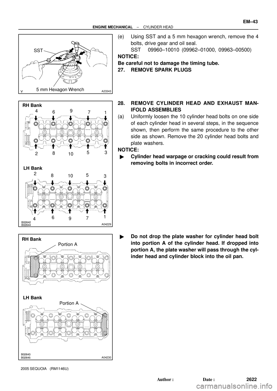
(e) Using SST and a 5 mm hexagon wrench, remove the 4
bolts, drive gear and oil seal.
SST 09960±10010 (09962±01000, 09963±00500)
NOTICE:
Be careful not to damage the timing tube.
27. REMOVE SPARK PLUGS
28. REMOVE CYLINDER HEAD AND EXHAUST MAN-
IFOLD ASSEMBLIES
(a) Uniformly loosen the 10 cylinder head bolts on one side
of each cylinder head in several steps, in the sequence
shown, then perform the same procedure to the other
side as shown. Remove the 20 cylinder head bolts and
plate washers.
NOTICE:
�Cylinder head warpage or cracking could result from
removing bolts in incorrect order.
�Do not drop the plate washer for cylinder head bolt
into portion A of the cylinder head. If dropped into
portion A, the plate washer will pass through the cyl-
inder head and cylinder block into the oil pan.