Page 1266 of 4323

SYSTEM DESCRIPTION
1. BRIEF DESCRIPTION
(a) The CAN (Controller Area Network) is a serial data c")
DIDI0±01
DI±1064
± DIAGNOSTICSCAN COMMUNICATION SYSTEM
1258 Author�: Date�:
2005 SEQUOIA (RM1146U)
SYSTEM DESCRIPTION
1. BRIEF DESCRIPTION
(a) The CAN (Controller Area Network) is a serial data communication system for real time application.
It is an in±vehicle multiplex communication system that has a high communication speed (500 kbps)
and the function to detect malfunctions.
(b) By pairing the CANH and CANL bus lines, the CAN performs communication based on differential volt-
age.
(c) Many ECUs (sensors) installed in the vehicle operate by sharing information and communicating with
each other.
(d) The CAN has two resistors of 120 W which are necessary to communicate with the main bus line.
2. DEFINITION OF TERMS
(a) Main bus line
(1) The main bus line is a wire harness between the two terminus circuits on the bus (communication
line). This is the main bus in the CAN communication system.
(b) Sub bus line
(1) The sub bus line is a wire harness that diverges from the main bus line to the ECU.
3. ECUs THAT COMMUNICATE THROUGH CAN COMMUNICATION SYSTEM
(a) Translate ECU
(b) Suspension Control ECU
(c) ECM
4. DIAGNOSTIC CODE FOR CAN COMMUNICATION SYSTEM
DTCs for the CAN communication system are as follows:
U0100/65, U0122/67, U0132/72, 65, 94.
HINT:
If C1201/51, C1202/52 or C1203/53 is output from skid control ECU, perform troubleshooting of each diag-
nosis code (see page DI±921).
5. REMARK FOR TROUBLESHOOTING
(a) Trouble in the CAN bus (communication line) can be checked from the DLC3 (except when there is
a wire break in lines other than the sub bus line of the DLC3).
NOTICE:
Do not insert the tester directly into the DLC3 connector. Be sure to use a service wire.
(b) The CAN communication system cannot detect trouble in the sub bus line of the DLC3 even though
the DLC3 is also connected to the CAN communication system.
6. HOW TO DISTINGUISH THE CAN J/C CONNECTOR
In the CAN communication system, all connectors connected to the CAN J/C are the same shape. The con-
nectors connected to the CAN J/C can be distinguished by the colors of the bus lines.
HINT:
See ºTERMINALS OF ECUº (see page DI±1068) for bus line colors.
Page 1270 of 4323
DIDI4±01
F19816
Junction Connector ºBº Side
(w/o Earth Terminal):Junction Connector ºAº Side
(w/ Earth Terminal):
Earth Terminal
Junction
ConnectorJ53
J54
J55
G
W L
W
B
W R W
J56 (*1) DI±1068
± DIAGNOSTICSCAN COMMUNICATION SYSTEM
1262 Author�: Date�:
2005 SEQUOIA (RM1146U)
TERMINALS OF ECU
HINT:
This section describes the standard CAN values for all CAN re-
lated components.
1. Junction Connector
HINT:
�The connectors connected to the junction connector can
be distinguished by the colors of the bus lines and the
connecting side of the connector.
�J53, J54, J55 and J56 are interchangeable.
�*1: w/ Air Suspension System
CAN J/C connectors
(A side, w/ earth terminal)Color (CAN±H Side)Color (CAN±L Side)
ECM (J53)LW
DLC3 (J54)BW
Translate ECU (J55)RW
Suspension Control ECU (J56) *1GW
Page 1271 of 4323
F19735
CAN J/C Connector Front View:
12345678
9 10111213141516
F19737
DLC3:
D6
CANH
CG
BAT
CANL
± DIAGNOSTICSCAN COMMUNICATION SYSTEM
DI±1069
1263 Author�: Date�:
2005 SEQUOIA (RM1146U)
2. The Terminals of Connectors for the Junction Con-
nector
TerminalTerminal symbol
1CANH
2CANL
3. DLC3
(a) Measure the resistance according to the value(s) in the
table below.
Standard:
TerminalsWiring ColorConditionSpecified Value
D6±6 (CANH) ± D6±14 (CANL)B ± WIgnition Switch OFF54 to 69 W
D6±6 (CANH) ± D6±4 (CG)B ± OIgnition Switch OFF3 kW or more
D6±14 (CANL) ± D6±4 (CG)W ± OIgnition Switch OFF3 kW or more
D6±6 (CANH) ± D6±16 (BAT)B ± W±RIgnition Switch OFF1 MW or more
D6±14 (CANL) ± D6±16 (BAT)W ± W±RIgnition Switch OFF1 MW or more
Page 1272 of 4323
F16975
Translate ECU:
T5 ENG+
ENG±
12345678
9 10111213141516
F19737F19152F19830
Translate ECU Wire Harness View:
T5
GND
ENG±
ENG+
DLC3:
D6
BAT
DI±1070
± DIAGNOSTICSCAN COMMUNICATION SYSTEM
1264 Author�: Date�:
2005 SEQUOIA (RM1146U)
4. Translate ECU
(a) Measure the resistance according to the value(s) in the
table below.
Standard:
TerminalsConditionSpecified Value
T5±14 (ENG+) ± T5±16 (ENG±)Ignition Switch OFF108 to 132 W
(b) Measure the resistance according to the value(s) in the
table below.
Standard:
TerminalsWiring ColorConditionSpecified Value
T5±14 (ENG+) ± T5±16 (ENG±)R ± WIgnition Switch OFF108 to 132 W
T5±14 (ENG+) ± T5±40 (GND)R ± OIgnition Switch OFF3 kW or more
T5±16 (ENG±) ± T5±40 (GND)W ± OIgnition Switch OFF3 kW or more
T5±14 (ENG+) ± D6±16 (BAT)R ± W±RIgnition Switch OFF1 MW or more
T5±16 (ENG±) ± D6±16 (BAT)W ± W±RIgnition Switch OFF1 MW or more
Page 1278 of 4323
DIDI8±01
F19697
Translate ECU
Junction ConnectorECM
ENG+
ENG±14
T5
16
T51
J55
2
J55 R
W1
J53
2
J5333
E5
34
E5 W L CANH
CANL
Suspension Control ECU
CANH
CANL29
S25
28
S25G
W (*1)
(*1)1
J56
2
J561
J54
2
J54W B
6
14D6 DLC3
CANH
CANL
Instrument Panel J/B
BAT
CG W±R 13
1F 1
1L W W
8
5
B16
4 O
A
A
OJ43
J/C
IG ALT F10
FL Block
Battery
*1: w/ Air Suspension SystemOBD
12 DI±1076
± DIAGNOSTICSCAN COMMUNICATION SYSTEM
1270 Author�: Date�:
2005 SEQUOIA (RM1146U)
CIRCUIT INSPECTION
Check CAN Bus Line
CIRCUIT DESCRIPTION
When any DTC of the CAN communication system is output, first measure the resistance between the termi-
nals of the DLC3 and the suspension control ECU connector to specify the trouble area.
WIRING DIAGRAM
Page 1279 of 4323
12345678
9 10111213141516
F19737
DLC3:
CANH
CANLD6
± DIAGNOSTICSCAN COMMUNICATION SYSTEM
DI±1077
1271 Author�: Date�:
2005 SEQUOIA (RM1146U)
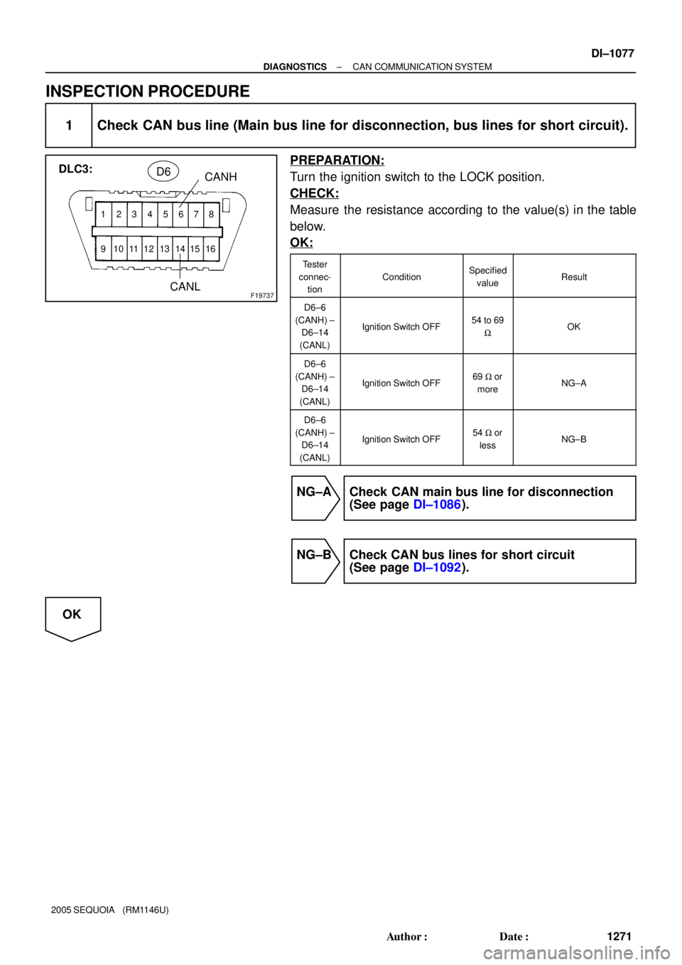
INSPECTION PROCEDURE
1 Check CAN bus line (Main bus line for disconnection, bus lines for short circuit).
PREPARATION:
Turn the ignition switch to the LOCK position.
CHECK:
Measure the resistance according to the value(s) in the table
below.
OK:
Tester
connec-
tion
ConditionSpecified
valueResult
D6±6
(CANH) ±
D6±14
(CANL)
Ignition Switch OFF54 to 69
WOK
D6±6
(CANH) ±
D6±14
(CANL)
Ignition Switch OFF69 W or
moreNG±A
D6±6
(CANH) ±
D6±14
(CANL)
Ignition Switch OFF54 W or
lessNG±B
NG±A Check CAN main bus line for disconnection
(See page DI±1086).
NG±B Check CAN bus lines for short circuit
(See page DI±1092).
OK
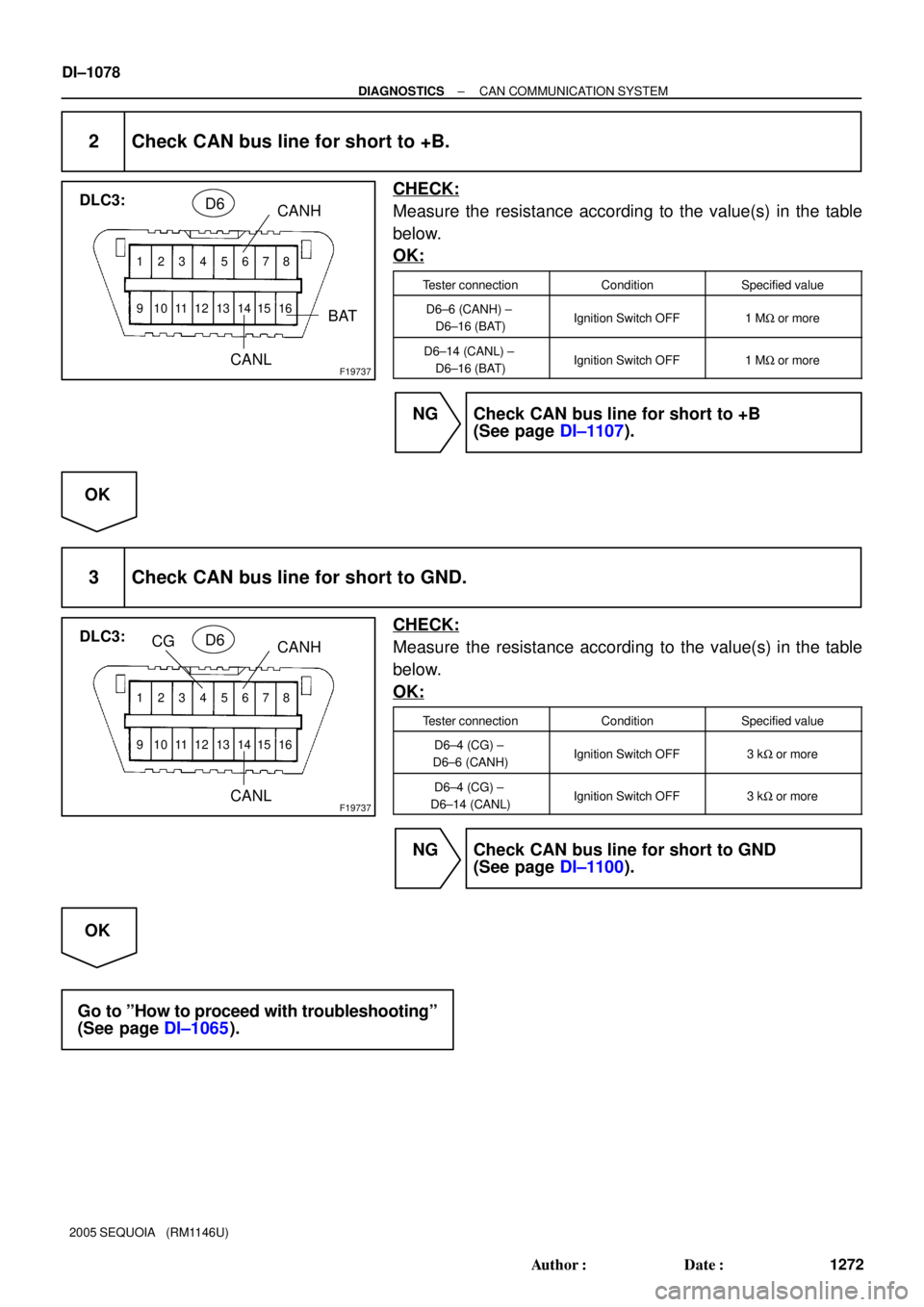
Page 1280 of 4323
12345678
9 10111213141516
F19737
DLC3:
CANH
CANLD6
BAT
12345678
9 10111213141516
F19737
DLC3:
CANH
CANLD6
CG
DI±1078
± DIAGNOSTICSCAN COMMUNICATION SYSTEM
1272 Author�: Date�:
2005 SEQUOIA (RM1146U)
2 Check CAN bus line for short to +B.
CHECK:
Measure the resistance according to the value(s) in the table
below.
OK:
Tester connectionConditionSpecified value
D6±6 (CANH) ±
D6±16 (BAT)Ignition Switch OFF1 MW or more
D6±14 (CANL) ±
D6±16 (BAT)Ignition Switch OFF1 MW or more
NG Check CAN bus line for short to +B
(See page DI±1107).
OK
3 Check CAN bus line for short to GND.
CHECK:
Measure the resistance according to the value(s) in the table
below.
OK:
Tester connectionConditionSpecified value
D6±4 (CG) ±
D6±6 (CANH)Ignition Switch OFF3 kW or more
D6±4 (CG) ±
D6±14 (CANL)Ignition Switch OFF3 kW or more
NG Check CAN bus line for short to GND
(See page DI±1100).
OK
Go to ºHow to proceed with troubleshootingº
(See page DI±1065).
Page 1288 of 4323
F19701
Translate ECU
ENG+
ENG±Junction Connector
14
T5
16
T5R
W1
J55
2
J551
J53
2
J53L
W33
E5
34
E5ECM
CANH
CANL
D6 DLC3
1
J54
2
J54B
W6
14CANH
CANL DI±1086
± DIAGNOSTICSCAN COMMUNICATION SYSTEM
1280 Author�: Date�:
2005 SEQUOIA (RM1146U)
Check CAN Main Bus Line For Disconnection
CIRCUIT DESCRIPTION
The CAN main bus line and DLC3 sub bus line may have a disconnection when the resistance between ter-
minals 6 (CANH) and 14 (CANL) of the DLC3 is more than 69 W.
SymptomTrouble Area
Resistance between terminals 6 (CANH) and 14 (CANL) of
the DLC3 is more than 69 W.
�CAN main bus line
�ECM
�Translate ECU
�DLC3 sub bus line
WIRING DIAGRAM
DIDIC±01
:Junction Connector ºAº Side
(w/ Earth Terminal):
Earth Terminal
Junction
ConnectorJ53
J54
J55
G
W L
W
B
W R W
J56 (*1) DI±1068
±")


(*1)1
J56
2
J561
J54")