Page 2158 of 4323
DID9K±01
I27726
Radio Receiver Assy
Rear Door Speaker Tweeter
Rear Door Speaker Front Door Speaker (*1)
Front Door Speaker and
Woofer (*2)Steering Pad
Switch
Instrument Panel J/B
� RAD NO. 2 Fuse
� ECU±B Fuse
� AM1 FuseEngine Room J/B
� RAD NO. 1 Fuse
� RAD NO. 3 Fuse
Ignition Switch
Disc Player
Controller
(*3)
Stereo
Component
AmplifierMulti±display
Controller (*3)
VTR
Terminal
(*3)Headphone
Terminal
(*3, *4)
Television Display Assy (*3)
Rear Seat Audio
Controller Assy (*4)
Radio Sub
Antenna*1: Built±in Type Amplifier
*2: Separate Type Amplifier
*3: w/ RSE System
*4: w/ RSA System Radio Main Antenna
DI±1956
± DIAGNOSTICSAUDIO SYSTEM
2150 Author�: Date�:
2005 SEQUOIA (RM1146U)
LOCATION
Page 2230 of 4323
DI±2028
± DIAGNOSTICSAUDIO SYSTEM
2222 Author�: Date�:
2005 SEQUOIA (RM1146U)
Radio broadcast cannot be received (Bad reception)
INSPECTION PROCEDURE
1 Check if radio auto±search functions properly.
CHECK:
Check if the radio auto±search functions properly.
Perform the auto±search of the radio and check that it functions normally.
OK:
The radio auto±search functions properly.
OK Replace radio receiver assy.
NG
2 Check optional component.
CHECK:
Check for any optional component (sun shade film, telephone antenna etc.).
Check whether or not any optional component such as a sun shade film and telephone antenna is
installed.
OK:
Optional component is not installed.
NG Effect from optional component.
OK
DIDA4±01
Page 2247 of 4323
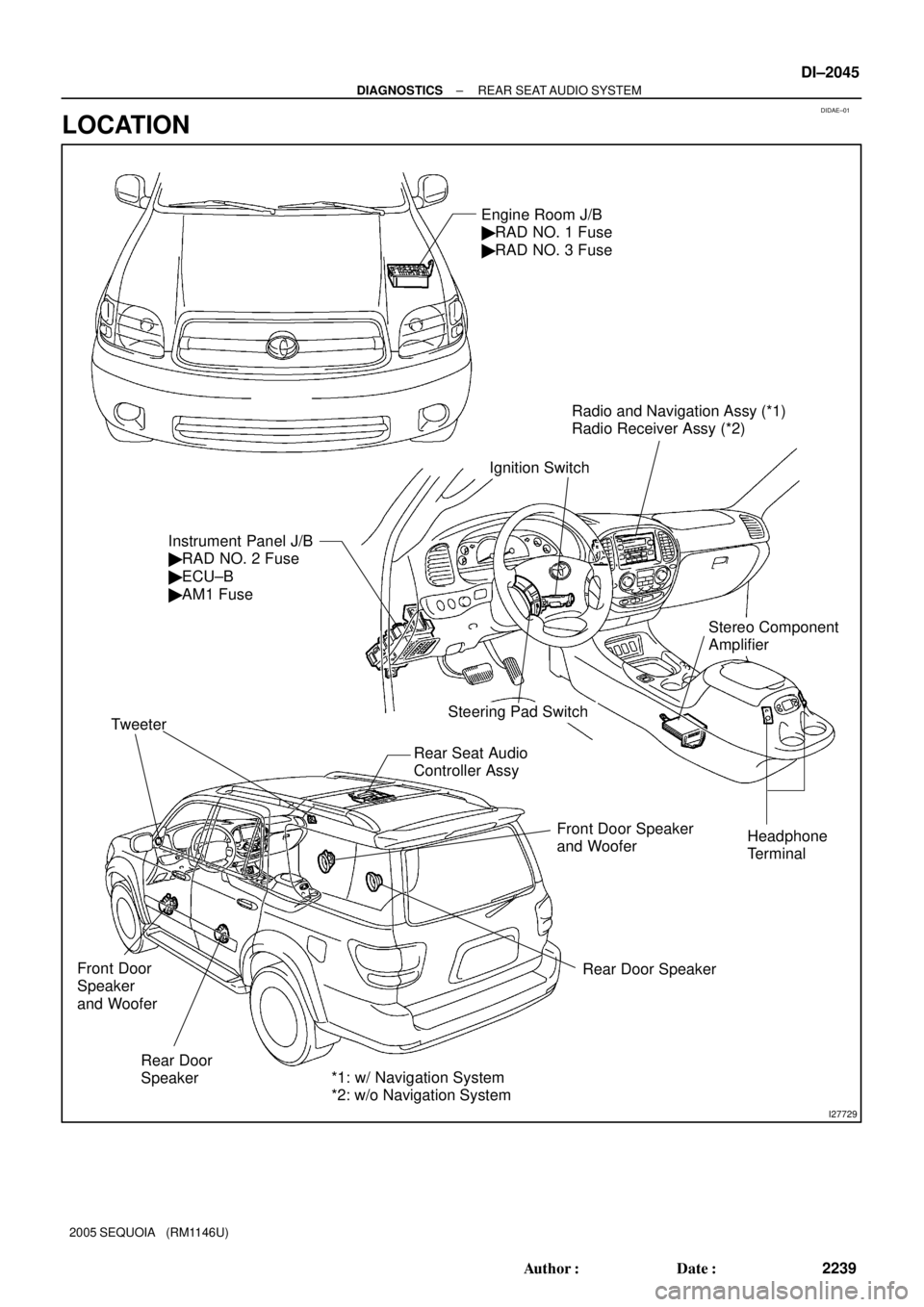
DIDAE±01
I27729
Radio and Navigation Assy (*1)
Radio Receiver Assy (*2)
Rear Door
Speaker Tweeter
Rear Door Speaker Front Door Speaker
and Woofer
Steering Pad Switch Instrument Panel J/B
� RAD NO. 2 Fuse
� ECU±B
� AM1 FuseEngine Room J/B
� RAD NO. 1 Fuse
� RAD NO. 3 Fuse
Ignition Switch
Rear Seat Audio
Controller Assy
Headphone
Terminal
Front Door
Speaker
and Woofer
Stereo Component
Amplifier
*1: w/ Navigation System
*2: w/o Navigation System
± DIAGNOSTICSREAR SEAT AUDIO SYSTEM
DI±2045
2239 Author�: Date�:
2005 SEQUOIA (RM1146U)
LOCATION
Page 2248 of 4323
DIDAF±01
I28753
Sound Signal
Rear Seat Audio Controller Radio Receiver Assy
or
Radio and Navigation
AssyAVC±LAN
Speakers Stereo Component
Amplifier Assy
Switch AssyWireless
HeadphoneHeadphone
Terminal
Wired Headphone Wired Headphone DI±2046
± DIAGNOSTICSREAR SEAT AUDIO SYSTEM
2240 Author�: Date�:
2005 SEQUOIA (RM1146U)
SYSTEM DIAGRAM
Page 2249 of 4323
DIDAG±01
I28272
AVC±LAN:
Stereo Component
Amplifier Assy� Radio Receiver Assy
(w/o Navigation)
� Radio and Navigation Assy
(w/ Navigation)
Rear Seat Audio Controller
: AVC LAN
± DIAGNOSTICSREAR SEAT AUDIO SYSTEM
DI±2047
2241 Author�: Date�:
2005 SEQUOIA (RM1146U)
SYSTEM DESCRIPTION
1. OUTLINE
(a) Rear Seat Audio (RSA) system, which consists of a rear seat audio controller and a remote controller
(switch assy), enables the rear seat occupants to use headphones to listen simultaneously to a differ-
ent audio mode than the one that is selected in the front audio head unit.
2. COMMUNICATION SYSTEM
Page 2251 of 4323
DIDAJ±01
RSA SYSTEM Check Sheet
Inspector 's name:
Customer 's NameVIN
Production Date
Licence Plate No.
Odometer Reading / /km
mile
Frequency of Problem Occurrence / /
� Constant � Intermittent ( Times a day) Brought±in Date
Date of First Occurrence
Problem
Symptom
� Headphone
DTC
Check
Parts name
DTC (1st time)DTC (2nd time) � Switch Assy
� Headphone Terminal � Rear Seat Audio Controller Assy
�
± DIAGNOSTICSREAR SEAT AUDIO SYSTEM
DI±2049
2243 Author�: Date�:
2005 SEQUOIA (RM1146U)
CUSTOMER PROBLEM ANALYSIS CHECK
Page 2252 of 4323

PROBLEM SYMPTOMS TABLE
RSA SYSTEM
SymptomSuspected AreasSee page
RSA system cannot be powered.1. P")
DIDAK±01
DI±2050
± DIAGNOSTICSREAR SEAT AUDIO SYSTEM
2244 Author�: Date�:
2005 SEQUOIA (RM1146U)
PROBLEM SYMPTOMS TABLE
RSA SYSTEM
SymptomSuspected AreasSee page
RSA system cannot be powered.1. Power source circuit (rear seat controller assy)DI±2058
Quality of sound from wireless headphone is poor or no sound
can be heard.
1. Power source circuit (rear seat controller assy)
2. Mute signal circuit (to rear seat audio controller)
3. Sound signal circuit (to rear seat audio controller)
4. Rear seat audio controllerDI±2058
DI±2066
DI±2070
±
Quality of sound from headphone connected to headphone termi-
nal is poor or no sound can be heard.
1. Power source circuit (rear seat controller assy)
2. Mute signal circuit (to rear seat audio controller)
3. Sound signal circuit (Rear seat audio controller ± head-
phone terminal)
4. Sound signal circuit (Radio receiver assy / radio and
navigation assy ± rear seat audio controller)DI±2058
DI±2066
DI±2073
DI±2070
REMOTE CONTROL
SymptomSuspected AreasSee page
A remote control system does not operate.
1. Power source circuit (rear seat controller assy)
2. A remote control system does not operate
3. AVC±LAN circuitDI±2058
DI±2076
DI±2061
Page 2253 of 4323

TERMINALS OF ECU
1. REAR SEAT AUDIO CONTROLLER
Terminals No. (Symbols)Wiring ColorTermi")
DIDAL±01
I28334
R24
± DIAGNOSTICSREAR SEAT AUDIO SYSTEM
DI±2051
2245 Author�: Date�:
2005 SEQUOIA (RM1146U)
TERMINALS OF ECU
1. REAR SEAT AUDIO CONTROLLER
Terminals No. (Symbols)Wiring ColorTerminal
DescriptionConditionSpecified value
R24±1 ± Body ground
(SGN1 ± Body ground)Shielded ±
Body groundGroundAlwaysBelow 1 V
R24±2 ± R24±17
(HP1L ± GND)BR ± LGSound signal
(Output)RSA system is sounding (Headphone)
A waveform syn-
chronized with
sounds is output
R24±3 ± R24±17
(HP1R ± GND)BR ± LGSound signal
(Output)RSA system is sounding (Headphone)
A waveform syn-
chronized with
sounds is output
R24±6 ± R24±17
(R±L± ± GND)W ± LGSound signal
(Input)RSA system is sounding
A waveform syn-
chronized with
sounds is output
R24±7 ± R24±17
(R±L+ ± GND)W ± LGSound signal
(Input)RSA system is sounding
A waveform syn-
chronized with
sounds is output
R24±8 ± R24±17
(R±R± ± GND)W ± LGSound signal
(Input)RSA system is sounding
A waveform syn-
chronized with
sounds is output
R24±9 ± R24±17
(R±R+ ± GND)W ± LGSound signal
(Input)RSA system is sounding
A waveform syn-
chronized with
sounds is output
R24±10 ± Body ground
(SG1 ± Body ground)Shielded ±
Body groundGroundAlwaysBelow 1 V
R24±11 ± R24±17
(RMUT ± GND)LG ± LGMute signalAudio system is playing " Changing modeAbove 3.5 V "
Below 1 V
R24±12 ± R24±17
(+B ± GND)LG ± LGBatteryAlways10 to 14 V
R24±13 ± Body ground
(SGN2 ± Body ground)Shielded ±
Body groundGroundAlwaysBelow 1 V
R24±14 ± R24±17
(HP2L ± GND)BR ± LGSound signal
(Output)RSA system is sounding (Headphone)
A waveform syn-
chronized with
sounds is output
R24±15 ± R24±17
(HP2R ± GND)BR ± LGSound signal
(Output)RSA system is sounding (Headphone)
A waveform syn-
chronized with
sounds is output
R24±17 ± Body ground
(GND ± Body ground)LG ±
Body groundGroundAlwaysBelow 1 W