Page 2254 of 4323
R24±22 ±R24±17 (TX+ ±
GND)
LG ± LG
AVC±LAN
c")
I28323
H10
H11
Headphone Terminal LH
Headphone Terminal RH DI±2052
± DIAGNOSTICSREAR SEAT AUDIO SYSTEM
2246 Author�: Date�:
2005 SEQUOIA (RM1146U)R24±22 ±R24±17 (TX+ ±
GND)
LG ± LG
AVC±LAN
communication
signal
Ignition switch ON2 to 3 V
R24±23 ±R24±17 (TX± ±
GND)LG ± LG
AVC±LAN
communication
signal
Ignition switch ON2 to 3 V
R24±24 ± R24±17
(ACC ± GND)LG ± LGIgnition (ACC)Ignition switch ON10 to 14 V
2. HEADPHONE TERMINAL
Terminal No. (Symbols)Wiring ColorTerminal
DescriptionConditionSpecified value
H10±1 ± H10±3
(HPR ± SGND)BR ± ShieldedSound signal
(Input)External device system sounding
(At that time of headphone terminal use)A waveform syn-
chronized with
sound is output
H10±2 ± H10±3
(HPL ± SGND)BR ± ShieldedSound signal
(Input)External device system sounding
(At that time of headphone terminal use)A waveform syn-
chronized with
sound is output
H10±3 ± Body ground
(SGND ± Body ground)Shielded ± Body
groundGroundAlwaysBelow 1 V
H11±1 ± H11±3
(HPR ± SGND)BR ± ShieldedSound signal
(Input)External device system sounding
(At that time of headphone terminal use)A waveform syn-
chronized with
sound is output
H11±2 ± H11±3
(HPL ± SGND)BR ± ShieldedSound signal
(Input)External device system sounding
(At that time of headphone terminal use)A waveform syn-
chronized with
sound is output
H11±3 ± Body ground
(SGND ± Body ground)Shielded ± Body
groundGroundAlwaysBelow 1 V
Page 2275 of 4323
I28601
H10
Headphone Terminal LHRear Seat Audio Controller
HP1R
ID2R243
BR W
HP1L ID2
R242
BR B
SGN1
ID2R241 3
2
1
(Shielded) (Shielded) BR
BR HPR
HPL
SGND
(Shielded)IF38
7
6
H11
Headphone Terminal RH
HP2R
ID2R2415
BR W
HP2L
ID2
R2414
BR B
SGN2
ID2R2413 19
18
17
(Shielded) (Shielded) BR
BR HPR
HPL
SGND
(Shielded)20
19
18 1
2
3
1
2
3IF3
IF3
IF3
IF3
IF3
± DIAGNOSTICSREAR SEAT AUDIO SYSTEM
DI±2073
2267 Author�: Date�:
2005 SEQUOIA (RM1146U)
Sound signal circuit (Rear seat audio controller ± headphone ter-
minal)
CIRCUIT DESCRIPTION
Music sound which is heard via the headphone terminal of the rear seat audio system is directly sent to the
headphones without being sent through the stereo component amplifier.
WIRING DIAGRAM
DIDAQ±01
Page 2277 of 4323
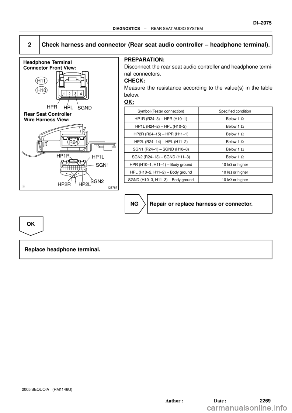
I28767
Headphone Terminal
Connector Front View:
Rear Seat Controller
Wire Harness View:H11
H10
HPRHPLSGND
SGN1
HP1L HP1R
SGN2HP2RR24HP2L
± DIAGNOSTICSREAR SEAT AUDIO SYSTEM
DI±2075
2269 Author�: Date�:
2005 SEQUOIA (RM1146U)
2 Check harness and connector (Rear seat audio controller ± headphone terminal).
PREPARATION:
Disconnect the rear seat audio controller and headphone termi-
nal connectors.
CHECK:
Measure the resistance according to the value(s) in the table
below.
OK:
Symbol (Tester connection)Specified condition
HP1R (R24±3) ± HPR (H10±1)Below 1 W
HP1L (R24±2) ± HPL (H10±2)Below 1 W
HP2R (R24±15) ± HPR (H11±1)Below 1 W
HP2L (R24±14) ± HPL (H11±2)Below 1 W
SGN1 (R24±1) ± SGND (H10±3)Below 1 W
SGN2 (R24±13) ± SGND (H11±3)Below 1 W
HPR (H10±1, H11±1) ± Body ground10 kW or higher
HPL (H10±2, H11±2) ± Body ground10 kW or higher
SGND (H10±3, H11±3) ± Body ground10 kW or higher
NG Repair or replace harness or connector.
OK
Replace headphone terminal.
Page 2281 of 4323
DIDAT±01
I27728
Radio and Navigation Assy (*1)
Radio Receiver Assy (*2)
Rear Door
SpeakerSteering Pad Switch
Instrument Panel J/B
� RAD NO. 2 Fuse
� ECU±B Fuse
� AM1 FuseEngine Room J/B
� RAD NO. 1 Fuse
� RAD NO. 3 Fuse
Ignition Switch
Headphone
Terminal
Front Door
Speaker and
Woofer
Stereo Component Amplifier
Multi±display
Controller
Sub±assy
*1: w/ Navigation System
*2: w/o Navigation SystemVTR TerminalDisc Player
Controller
Rear Door
Speaker
Front Door
Speaker and
Woofer
Tweeter
Television Display Assy
± DIAGNOSTICSREAR SEAT ENTERTAINMANT SYSTEM
DI±2079
2273 Author�: Date�:
2005 SEQUOIA (RM1146U)
LOCATION
Page 2282 of 4323
DIDAU±01
I28762
Radio and Navigation Assy
(*1)
or
Radio Receiver Assy (*2)
VTR
TerminalSpeakers Stereo Component
Amplifier Assy
Multi±display Controller
Wireless
HeadphoneDisplay Signal
Sound Signal
AVC±LAN
Headphone
Terminal
Switch AssyDisc
Player
ControllerTelevision
Display
Assy
*1: w/ Navigation System
*2: w/o Navigation System DI±2080
± DIAGNOSTICSREAR SEAT ENTERTAINMANT SYSTEM
2274 Author�: Date�:
2005 SEQUOIA (RM1146U)
SYSTEM DIAGRAM
Page 2283 of 4323

SYSTEM DESCRIPTION
1. Outline
�As a unique feature of Rear Seat Entertainment (RSE) system")
DIDAV±01
± DIAGNOSTICSREAR SEAT ENTERTAINMANT SYSTEM
DI±2081
2275 Author�: Date�:
2005 SEQUOIA (RM1146U)
SYSTEM DESCRIPTION
1. Outline
�As a unique feature of Rear Seat Entertainment (RSE) system, the front and rear seat occupants can
enjoy different audio±visual modes at the same time. Thus, this system offers enhanced entertainment
to the rear seat occupants.
�The rear seat occupants can control the audio±visual modes with the remote controller (switch assy),
and listen to audio by using wired or wireless headphones.
�The RSE system is controlled by the multi±display controller, and the communication among the audio
head unit, rear display assembly, and DVD player is established via an AVC±LAN (Audio Visual Com-
munication±Local Area Network).
2. Function of Main Component
Television Display Assy
�Displays DVD and video images in accordance with video signals from the RSE ECU.
�Receives signals from the remote controller and outputs them to the RSE ECU.
�Outputs audio signals to the wireless headphones in the form of infrared signals.
�Displays the audio±visual control screen.
�Displays the adjustment screen.
�Displays the diagnosis screen.
�The diagnosis screen appears when the diagnosis mode is started on the audio head unit.
Audio Head Unit
w/ Navigation system:
Radio and navigation assy
w/o Navigation system:
Radio receiver assy
�Outputs audio signals to the RSE ECU and the stereo component amplifier.
�Outputs a request to the RSE ECU to start the diagnosis mode.
RSE ECU (Multi±display Controller)
�Processes video and audio signals from the DVD player and video player and audio signals from the
audio head unit, and outputs them to the television display assembly and headphone terminals.
�Controls the distribution of the audio±visual mode to the front (audio head unit) and the rear (RSE).
Remote Controller (Switch Assy)Outputs various control signals of the RSE system to the television display assembly in the form of in-
frared signals.
Wireless Headphone
�Receives the audio signals from the television display assembly in the form of infrared signals.
�Volume adjustment of the wireless headphone can be done by using the volume equipped on the wire-
less headphone.
Headphone Terminal�Outputs audio signals to the wired headphones that are connected.
�Adjusts the volume of the wired headphones in accordance with volume control.
VTR TerminalThis terminal is for connecting the video player's video and audio output terminals.
Page 2286 of 4323
DIDAX±01
I28289
RSE SYSTEM Check Sheet
Inspector 's name:
Customer 's NameVIN
Production Date
Licence Plate No.
Odometer Reading / /km
mile
Frequency of Problem Occurrence / /
� Constant � Intermittent ( Times a day) Brought±in Date
Date of First Occurrence
Problem
Symptom
� Headphone
DTC
Check
Parts name
DTC (1st time).DTC (2nd time). � Switch Assy
� Disc Player Controller � Multi±display Controller Sub±assy
� Television Display Assy
�
Disc Player Controller
Television Display Assy DI±2084
± DIAGNOSTICSREAR SEAT ENTERTAINMANT SYSTEM
2278 Author�: Date�:
2005 SEQUOIA (RM1146U)
CUSTOMER PROBLEM ANALYSIS CHECK
Page 2290 of 4323
 Only sound quality input from the external device is poor or no
sound can be heard.
1. Power source")
DI±2088
± DIAGNOSTICSREAR SEAT ENTERTAINMANT SYSTEM
2282 Author�: Date�:
2005 SEQUOIA (RM1146U) Only sound quality input from the external device is poor or no
sound can be heard.
1. Power source circuit (multi±display controller sub±assy)
2. Power source circuit (television display assy)
3. Sound signal circuit (multi±display controller sub±assy ±
VTR terminal)
4. VTR terminal
5. Multi±display controller sub±assyDI±2110
DI±2107
DI±2131
±
±
The operation the external device cannot be performed
1. Power source circuit (multi±display controller sub±assy)
2. Power source circuit (television display assy)
3. VTR terminal set signal circuit
4. VTR terminal
5. Multi±display controller sub±assyDI±2110
DI±2107
DI±2155
±
±
RSE SYSTEM
SymptomSuspect AreaSee page
Quality of sound from wireless headphone is poor or no sound
can be heard (all sound).
1. Power source circuit (multi±display controller sub±assy)
2. Power source circuit (television display assy)
3. Sound signal circuit (multi±display controller sub±assy ±
television display assy)
4. Mute signal circuit (radio receiver assy ± multi±display
controller sub±assy)
5. Mute signal circuit (disc player controller ± multi±display
controller sub±assy)
6. Multi±display controller sub±assy
7. Television display assyDI±2110
DI±2107
DI±2135
DI±2147
DI±2153
±
±
Quality of sound from headphone connected to headphone termi-
nal is poor or no sound can be heard (all sound).
1. Power source circuit (multi±display controller sub±assy)
2. Power source circuit (television display assy)
3. Sound signal circuit (multi±display controller sub±assy ±
headphone terminal)
4. Mute signal circuit
5. Multi±display controller sub±assy
6. Television display assyDI±2110
DI±2107
DI±2133
DI±2147
±
±
Quality of sound from wireless headphone is poor or no sound
can be heard (DVD sound only).
1. Power source circuit (disc player controller)
2. Sound signal circuit (multi±display controller sub±assy ±
disc player controller)
3. Disc player controller
4. Multi±display controller sub±assyDI±2112
DI±2137
±
±
Quality of sound from headphone connected is poor or no sound
can be heard (DVD sound only).
1. Power source circuit (disc player controller)
2. Sound signal circuit (multi±display controller sub±assy ±
disc player controller)
3. Disc player controller
4. Multi±display controller sub±assyDI±2112
DI±2137
±
±
 (Shielded) BR
BR HPR
HPL
SGND
(Shielded)IF38
7
6
H11
Headphone Terminal RH")


or
Radio Receiver Assy (*2)
VTR
TerminalSpeakers Stereo Component
Amplifier Assy
Multi±display Controller
Wireless
HeadphoneDisplay Signal
Sound Sig")
